


Applying DevOps to COBOL applications and CICS policies
This chapter looks at implementing a development and operations (DevOps) process for CICS COBOL applications and a CICS policy. It reviews how CICS applications and CICS policies are built in Rational Team Concert and published to an IBM UrbanCode Deploy repository. It then reviews the process of orchestrating and automating deployment of the applications to the target platform.
In this example, we use the GENAPP sample application and focus on a traditional CICS/COBOL DB2 application implementation and a CICS policy.
This chapter covers the following topics:
5.1 Current challenges
Many mainframe customers have CICS based core applications that require new functions and policy changes from time to time. Competitive business factors also push companies to adapt their applications at a faster rate. But, the application delivery pipeline is often limited by factors, such as the following ones:
•Disparate development and production environments.
•Complex, manual release processes that lack repeatability and speed.
•Costly and inefficient release processes can consume days of work effort.
Fortunately, there are tools that can help mitigate some of these challenges. Rational Team Concert, various CICS Tools and toolkits, and IBM UrbanCode Deploy provide the capabilities to support continuous delivery of enterprise applications. These tools help accelerate delivery by reducing cycle time to develop and test applications across heterogeneous environments. These tools help you reduce costs and minimize delays around delivering mainframe applications.
Here are some examples of how these tools address specific needs of continuous delivery and DevOps in general:
•Rational Team Concert provides tools for z/OS builds and CICS Application and Bundle projects to support continuous builds.
•The IBM CICS Transaction Server build toolkit (CICS build toolkit) can be started from Ant Scripts to deploy CICS applications and Bundles. IBM UrbanCode Deploy has a component that is called Buztool to deploy z/OS artifacts. With these tools, you can deploy CICS projects to build repositories.
•z/OS Plug-ins for IBM UrbanCode Deploy can be used to FTP, copy, and deploy Partitioned data sets.
•You can use the CICS Plug-in for IBM UrbanCode Deploy use NEWCOPY to copy programs and deploy CICS applications and bundles.
The following sections describe specific steps to implementing and deploying the different components of the GENAPP application.
5.2 Implementing the GENAPP base component
This section introduces the build and deployment of the GENAPP base COBOL application by using the DevOps approach.
5.2.1 Building the CICS application
In this scenario, the CICS/COBOL source code is pre-compiled bind and link-edited. The load modules and DBRM are made available in staging data sets that are named CICSDPP.SCEN1.LOAD and CICSDPP.SCEN1.DBRMLIB. The ship list file is created.
The ship list file specifies which files from the build must be included in the new component version to deploy. You must create a ship list file before you run the deployment tools.
Ship list files are XML files that contain a list of file specifiers. The container type that is used to identify partitioned data set (PDS) resources is PDS, and the resource type is PDSmember.
Figure 5-1 shows the output of the build process for COBOL applications.

Figure 5-1 COBOL build
Example 5-1 shows the ship list file that is already created for the example component.
Example 5-1 shiplist.xml
<?xml version="1.0" encoding="CP037"?>
<manifest type="MANIFEST_SHIPLIST">
<container name="CICSDPP.SCEN1.LOAD" type="PDS" deployType="CICS_LOAD">
<resource name="*" type="PDSMember"/>
</container>
<container name="CICSDPP.SCEN1.DBRMLIB" type="PDS" deployType="DBRM">
<resource name="*" type="PDSMember"/>
</container>
</manifest>
5.2.2 Defining a component in IBM UrbanCode Deploy
IBM UrbanCode Deploy z/OS Deploy Toolkit provides a command-line utility that is called Buztool that is used to deploy z/OS artifacts.
Buztool creates the z/OS component version in IBM UrbanCode Deploy CodeStation. CodeStation is not a separate product. It is simply a name that is given to the versioned storage area that is provided in IBM UrbanCode Deploy.
Before you can build a version of a component by using Buztool, first you must define the component by completing the following steps:
1. Log in to IBM UrbanCode Deploy and click Components → Create Component. In this example, we name our component GENAPP Base for the COBOL components. Specify the rest of the parameters, as shown in Figure 5-2.

Figure 5-2 Create the GENAPP component
2. Click Save, which creates the component that is called GENAPP Base. The window that opens is the component dashboard window, which shows that the component was created, as shown in Figure 5-3.

Figure 5-3 Component dashboard showing that the component was created
5.2.3 Running Buztool
You must run Buztool to generate a new version of the component and put the artifacts into UCD CodeStation.
Figure 5-4 illustrates how the component version is created by Buztool.

Figure 5-4 Buztool deploys the component version
You can run Buztool by using JCL in a batch job. A sample JCL is provided as part of the SMP/E installation and is found in a data set that is named <HLQ>.UCDTLKT.SBUZSAMP, where <HLQ> is the high-level qualifier that is used during the installation. In this example, the sample data set is REDS01.UCD.UCDTLKT.SBUZSAMP.
You can access the data set from the CICS Explorer z/OS perspective. Use Figure 5-5 (taken from CICS Explorer) as a reference, and filter for REDS01.UCD as high-level qualifier to find the sample data set.

Figure 5-5 Location of sample Buztool JCL in the CICS Explorer z/OS perspective
The sample JCL BUZRJCL was copied to the local data set, was renamed BUZTOOL, and customized to our environment, as shown in Figure 5-6.

Figure 5-6 Buztool JCL
Example 5-2 shows a sample of the JCL. For this example, we customized the JCL according to our environment. We were careful about using the following options:
-c Component name
-v Sets the version
-s Path of the shiplist.xml file
Example 5-2 Sample JCL
//ST1 EXEC PGM=IKJEFT01,DYNAMNBR=30,PARM='%ISPFCL',REGION=0M
//SYSEXEC DD DSN=REDS01.UCDTLKT.SBUZEXEC,DISP=SHR
// DD DSN=SYS1.SISPCLIB,DISP=SHR
//SYSTSPRT DD SYSOUT=*
//PROFILE DD DSN=REDS01.UCDTLKT.SBUZSAMP(MYPROF),DISP=SHR
//ISPPROF DD RECFM=FB,LRECL=80,SPACE=(TRK,(2,2,2))
//ISPLLIB DD DSN=SYS1.SISPLOAD,DISP=SHR
//ISPMLIB DD DSN=SYS1.SISPMENU,DISP=SHR
//ISPTLIB DD DSN=SYS1.SISPTENU,DISP=SHR
//ISPPLIB DD DSN=SYS1.SISPPENU,DISP=SHR
//ISPSLIB DD DSN=SYS1.SISPSLIB,DISP=SHR
//SYSTSIN DD *
ISPSTART CMD(BUZTOOL "createzosversion" -
"-c" "GENAPP Base" -
"-v" "version2" -
"-s" "/var/cicsts/devops/scenario1/build/shiplist.xml")
/*
After you customize the JCL, right-click and submit the z/OS job, as shown in Figure 5-7 on page 73.

Figure 5-7 Run the Buztool JCL
After the job finishes, you can see the results, as shown in Figure 5-8.

Figure 5-8 Result of the Buztool JCL job
You should have a component version that is named version2 of the GENAPP Base component in IBM UrbanCode Deploy CodeStation, as shown in Figure 5-9.

Figure 5-9 Component version2 created
To look at the version of the component that is created, click the Versions tab in IBM UrbanCode Deploy and refresh. You should see version2 there. Click version2, and you see the list of artifacts that was specified in the shiplist.xml file, as shown in Figure 5-10.

Figure 5-10 Component version artifacts
5.2.4 Creating and defining a component process
In this section, you create a component process to deploy the GENAPP Base component. Figure 5-11 shows the complete deployment process that you create. Each box in the figure represents a different step.

Figure 5-11 Component process for GENAPP base
1. The FTP Artifacts step retrieves the artifacts (CICS Load modules and DRMB) from the IBM UrbanCode Deploy repository and puts them into a working directory.
2. The Deploy Data Sets steps copy these artifacts from the working directory into the data sets. The process branches off to two parallel subprocesses: a CICS Load module step and DBRM0-related steps.
3. The Find CICS Load Member step generates the list of load module member names to prepare for the New Copy step.
4. The Find DBRM Lib and Find DBRM Member steps are the preparation steps to generate a DBRM library data set name and a DBRM member list.
5. The Bind Package and Bind Plan steps perform the binding with DB2.
6. Only when both branches run successfully does the process proceed to the New Copy step, which installs the artifacts.
Here are the details of defining this process and the individual steps:
1. Go to the Processes tab under component GENAPP Base and click Create Process, as shown in Figure 5-12.

Figure 5-12 Create process for the GENAPP Base component
2. Define the Deploy process, as shown in Figure 5-13. Name it Deploy, add a description, and configure the rest of the fields. Click Save.

Figure 5-13 Create the Deploy process
3. You should now see a process called Deploy created. Click the process or Edit. The design window opens, where you define the steps. Figure 5-14 shows the layout of the Design tab in process designer window. On the left side, below the Design tab label, there are six buttons, which are zoom in, zoom out, actual size, print preview, save, and discard changes.

Figure 5-14 Process designer window
It is a preferred practice to save changes as you create the process and before you move on to other tasks, especially if you are accessing an IBM UrbanCode Deploy Server through a remote connection or VPN.
Moving down from the buttons and the zoom window, there is the Step Palette with lists of available steps that are grouped in categories. Additional steps can be added by installing additional plug-ins. There is a search box that you can use search by using a key word to find specific steps quickly. On the right side is the process design canvas where you create your process flow.
FTP Artifacts
To retrieve the artifacts (CICS Load modules and DRMB) from the IBM UrbanCode Deploy repository and put them into a working directory, complete the following steps:
1. Enter FTP into the search box to find the FTP Artifact step (Figure 5-15).

Figure 5-15 FInd the FTP Artifact step by using the search box
2. Drag the FTP Artifacts step and drop it into the design canvas on the right. An Edit Properties window opens, where you specify the parameters (Figure 5-16 on page 79). Give it a name and leave most of the other values as the defaults.

Figure 5-16 Specify properties for the FTP Artifacts step
3. Pay attention to the following items:
– Directory Offset field: Make sure that there is a dot, which indicates that the current working directory is used.
– Show Hidden Properties: Select this box to see the list of hidden properties.
– All the fields that are marked with an '*' are mandatory and cannot be left blank.
– Many of the properties apply in a larger context beyond this specific component process. Therefore, keep the variable format ($p{…}) rather than hardcoding them to make the process more flexible and reusable without the need for modification. It is important to make sure all the variable properties here are defined in components, applications, agents, or other contexts.
– ${p:variable name} is the syntax for pointing to the value of the variable. The value of the variable that is specified must be successfully resolved during the running of the process or the process fails.
– ${p?:optional variable name} indicates that this variable is optional. If it is not set to a value, then an empty string is used and the process can still run.
Each of the fields has an explanation, which is available to the right of the field when you hover your cursor over the field (marked by a circle with a question mark).
4. Click OK and you see the first step that you created on the canvas. Hover your cursor over the Start box until a blue circle with an arrow appears, as shown in Figure 5-17.

Figure 5-17 Hover your cursor over Start until you see a circle with arrow
5. Click the circle and drag it to the FTP Artifacts step to connect the two boxes. You see a connecting arrow after you complete the connection, as shown in Figure 5-18.

Figure 5-18 Connect the Start and FTP Artifacts steps
Create the other steps of the deployment process in the same manner. The next section shows the properties that we use in this example.
Deploying data sets
This step copies the artifacts to the CICS load library and DBRM library. The PDS Mapping that is shown below means copy anything originally in a library ending with .LOAD to CICSDPP.CB12V51.LOAD, which is the CICS load library that is used in our example. Similarly, the second line means copy anything originally from a library that ends with .DBRMLIB to CICSDPP.CB12V51.DBRMLIB, which is the DBRM library that is used in our example.
*.LOAD,CICSDPP.CB12V51.LOAD
*.DBRMLIB,CICSDPP.CB12V51.DBRMLIB
For more information, see Figure 5-19 on page 81.
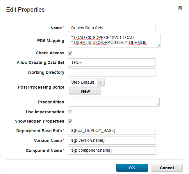
Figure 5-19 Deploy data sets step properties
Finding CICS load members
This step generates the list of load module member names to prepare for the New Copy step:
1. Search for “generate art”, and then click Generate Artifact Information under the z/OS utility, as shown in Figure 5-20.

Figure 5-20 FInd the Generate Artifact Information step from the Step Palette
2. Specify the properties. Figure 5-21 shows the values that we use in our scenario.

Figure 5-21 Find the CICS Load Member step properties
Table 5-1 lists several properties of particular note.
Table 5-1 Properties to note for the Find CICS Load Members step
|
Property name
|
Value
|
Explanation
|
|
For Each
|
PDS Member
|
For each member in the PDS data set
|
|
Deploy Type Filter
|
CICS_LOAD
|
Artifacts with a type=CICS_LOAD
|
|
Template
|
${member},
|
List member names separated by comma
|
Finding the DBRM Lib
This is one of the two preparation steps for DB2 bind. It generates the DBRM library data set name that is used in the DB2 Bind steps. Figure 5-22 shows the values that we specified in our example.

Figure 5-22 Find the DBRM Lib step properties
Table 5-2 lists several properties of particular note.
Table 5-2 Properties to note for Find CICS Load Members step
|
Property name
|
Value
|
Explanation
|
|
For Each
|
PDS
|
For each PDS data set.
|
|
Deploy Type Filter
|
DBRM
|
Artifacts with a type=CICS_LOAD.
|
|
Template
|
${dataset}
|
Generate the data set name for the DBRM library. We are expecting only one here.
|
Finding the DBRM Member
This is second of the two preparation steps for DB2 bind. It generates the DBRM member list that is used in the DB2 Bind steps. Figure 5-23 shows the values that we specified in our example.
Pay special attention to the For Each, Deploy Filter Type and Template fields.

Figure 5-23 Find the DBRM Member step properties
Bind Package step
Now that you have the DBRM library name and DBRM members list from the previous steps, create a DB2 Bind Package. Find the bind steps by using the Step Palette, as shown in Figure 5-24 on page 85.

Figure 5-24 Find the bind steps
Figure 5-25 shows how the properties are configured in our scenario.

Figure 5-25 Bind Package step properties
In particular, the MEMBER and LIBRARY properties take information that is generated from previous steps, as shown in Table 5-3.
Table 5-3 Specify the DBRM information in bind by using information from previous steps
|
Property name
|
Value
|
Explanation
|
|
MEMBER*
|
${p:Find DBRM Member/text}
|
Take the DBRM data set name that is generated from the Find DBRM Lib step.
|
|
LIBRARY*
|
${p:Find DBRM Lib/text}
|
Take the DBRM member list that is generated from the Find DBRM Member step.
|
|
Note: Selecting the Show Hidden Properties check box shows the list of hidden properties for this step. However, you might not need to specify all the properties. Which properties are required for the binding depends on how the system is set up in your environment. Typically, the DB2 administrator in the organization has this information. All the properties that are specified must be resolved during process execution. Unresolved properties result in the step and process failing. So, blank out the properties that are not needed.
|
Most of the binding properties describe the behavior of the application and how it interacts with DB2. Therefore, it is a preferred practice to specify the value of these properties at the application level. Figure 5-26 shows where you can define application properties. Click the Applications tab, select your application (for example, GENAPP COBOL+Policy), and click Configuration → Application Properties.

Figure 5-26 Specify the application properties
Bind Plan step
Similar to Bind Package, define a Bind Plan step, as shown in Figure 5-27.

Figure 5-27 Bind Plan step properties
New Copy step
Now we are ready to install the artifacts by completing the New Copy step. Define the properties that are shown in Figure 5-28. For Resource Name List, use the following syntax to get the list of programs from the Find CICS Load Member step:
${p:Find CICS Load Member/text}

Figure 5-28 New Copy step properties
Now, you have all the steps that are needed to deploy the component GENAPP Base. Make sure to connect all the steps from start to finish to complete the process.
5.2.5 Defining resources and adding a component to them
IBM UrbanCode Deploy resources represent system topologies, including logical partitions, databases, application servers, and so on. Before you can deploy any application, you must define the resources to which the artifacts are to be deployed.
Figure 5-29 on page 89 shows the resource tree that we created for this scenario. We use “Sandbox Sysplex”. Within the Sandbox Sysplex, we have an LPAR named DevOps LPAR, and an agent for this LPAR called WINMVSH1, under which we have an IBM CICSPlex® with region CICSDA01 and a DB2 subsystem called DJH1.

Figure 5-29 Resource tree
Complete the following steps:
1. Create the resource tree that is shown in Figure 5-30 by creating the top-level resource group Sandbox Sysplex. To do so, click Resources → Resource Tree → Create Top-Level Group.

Figure 5-30 Create top-level resource group
2. Click Save. Your top-level resource group Sandbox Sysplex is created.
3. Hover your cursor over the Sandbox Sysplex and an Actions menu appears. Click the drop box to see the list of actions that are available, as shown in Figure 5-31.

Figure 5-31 Add resources
4. Select Add Group to add other resources under Sandbox Sysplex to complete the resource tree according to the figure.
5. Click Add Agent to select the agent for this LPAR from the list of installed agents (assuming the agent is installed).
Next, you must add a component to resources. This can either be done from Resource Tree or from Application Environment Resource. In this example, we add the component from Resource Tree. As the GENAPP Base component is a CICS component, we add it to the CICS region CICSDA01 where it will be deployed.
Complete the following steps:
1. Hover your cursor over CICSDA01 and click Actions. Select Add Component, as shown in Figure 5-32 on page 91.

Figure 5-32 Add a component to resources
2. Select GENAPP Base from the list of components and click Save. You see that the component is associated to the CICS Region CICSDA01, as shown in Figure 5-33.

Figure 5-33 Component GENAPP Base added to resource CICSDA01
5.2.6 Creating an application and environment for GENAPP
To run a deployment process of one or more components, an application containing these components must be defined together with the application environments and application processes.
The application environment must have resources that are associated with them. So, this section shows how to create these definitions.
Creating the GENAPP application
To create the GENAPP application, complete the following steps:
1. In the Applications tab, click Create Application. In this example, name it “GENAPP Application” (see Figure 5-34).

Figure 5-34 Create Application - GENAPP Application
2. Click Save. The application is created and you automatically are taken to the application under the Environment tab.
Adding a component to the application
Now, you must add the GENAPP Base component to the application. Click the Components tab under Application. Make sure that it is the Components tab within the application and not the primary components table on the top. Then, click Add Component and select GENAPP Base, as shown in Figure 5-36 on page 94.

Figure 5-35 Add the GENAPP Base component to the application
Multiple components can be selected to be added to an application. However, in this example select only GENAPP Base.
Creating a development environment
Application environments are a collection of resources to host the application. Applications must have at least one environment as the target for deployment.
Complete the following steps:
1. To create a Development environment, click the Environment tab under Application and then click Create Environment, as shown in Figure 5-36.

Figure 5-36 Create a development environment
2. Click Save to create the environment.
3. Click the development environment.
4. Under the Resources tab, click Add Base Resources to select the resources for this environment.
5. Select the Sandbox Sysplex, as shown in Figure 5-37 on page 95. This step associates the whole sysplex and resources under it to this environment, including the GENAPP Base component that was added to CICSDA01.
6. Click OK to save.

Figure 5-37 Add a resource to an environment
5.2.7 Defining the application deployment process
You have the elements defined (component, application, resources, and environment). Now, you must define the application process to deploy this application.
Complete the following steps:
1. Click the Processes tab under Application.
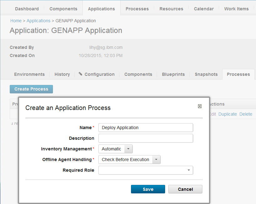
Figure 5-38 Create an application process for GENAPP Application
3. Click Save to create the process.
Similar to defining the GENAPP base component process, define the steps for this application process by completing the following steps:
1. Click the deployment application process that you created to open the process design canvas, as shown in Figure 5-39 on page 97.

Figure 5-39 Application process to install GENAPP Base
As application processes are concerned only with the component level, it is typical for an application process to be an assembly of its component processes.
The Step Palette for application process has a much shorter list of steps that represent operations on components such installation, uninstallation, rollback, and so on.
As there is only one GENAPP Base component in the example application at the moment, create a rather simple process with only one step to deploy the GENAPP Base component. This step starts the component process “Deploy” that was defined for the GENAPP Base component.
2. Select Install Component from the Step Palette and configure the properties, as shown in Figure 5-40.

Figure 5-40 Configure the installation component step to deploy the GENAPP Base component
3. Click OK to save.
4. Connect the start and finish and save the process.
5.2.8 Deploying the GENAPP Base component in the Application
Now, you can run the application process, which starts the component deployment process to install the GENAPP Base component into the environment. Complete the following steps:
1. Click Applications → GENAPP Application → Environments.
2. Click Play to request the process, which is marked by a circle with an arrow inside it, as shown in Figure 5-41 on page 99.

Figure 5-41 Request a process in the environment
3. In the Run Process on the Development window, select Deploy Application from the drop-down list as the process.
4. Click Choose Versions in the Component Versions window, and add the latest version to be deployed. In this example, as shown in Figure 5-42, it is version 3.

Figure 5-42 Select component version
5. Click OK to save and submit the process. The process execution window opens, which shows the progress of the process and the status of each step. Figure 5-43 shows the successful completion of the process.

Figure 5-43 Process execution successful
You have completed the build and deployment of the GENAPP Base component.
5.3 Implementing the GENAPP Policy component
This section describes how to add a CICS policy to the GENAPP Base component. Policies were introduced in CICS Transaction Server V5 and are used to protect critical system resources. In this example, we use a policy that generates a system message when the application exceeds a CPU Time threshold.
Assume that the policy bundle is defined and delivered to Rational Team Concert. Focus only on the build and deployment processes.
5.3.1 Creating a build definition
This section describes the steps that are necessary to create a build definition and create a CICS Bundle for the CICS Policy.
The first step is to create a new build definition for a CICS Policy in Rational Team Concert. Complete the following steps:
1. In the Team Artifacts tab of Rational Team Concert, right-click the Builds folder and select New Build Definition, as shown in Figure 5-44.

Figure 5-44 New Build Definition
Use the New Build Definition wizard to create a build definition.
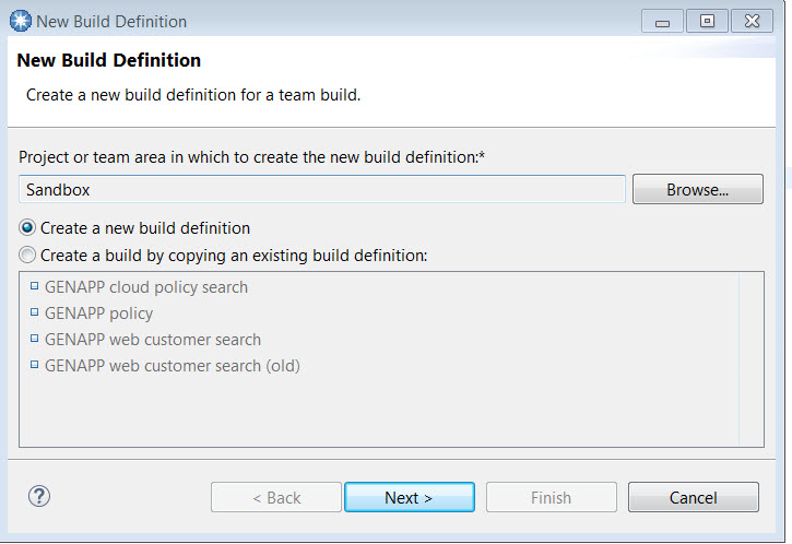
Figure 5-45 Create a build definition
3. Enter GENAPP CICS Policy in both the ID and the Description fields. The ID is the unique name of the build definition. Select the build template from the list of available templates.
4. Select Ant- Jazz Build Engine from the Available build templates and click Next (see Figure 5-46).

Figure 5-46 Build ID and template
5. The Pre-Build window opens and prompts you for the source code management (SCM) system. In this scenario, use Rational Team Concert and select Jazz Source Control, as shown in Figure 5-47 on page 103. Click Next.

Figure 5-47 Pre-Build option for Jazz Source Control
6. The Post-Build window opens (Figure 5-48). This is an important step for this scenario because you configure the post-build step to publish artifacts to the IBM UrbanCode Deploy CodeStation. Select Post build Deploy and click Finish.

Figure 5-48 Post build Deploy option
With the build definition created, configure each one of the tabs for this scenario. Start with the Overview tab and add the build engines. (The Jazz Build engine was created earlier and is available for use.)

Figure 5-49 Add build engine
8. Select the build engines that the build definition uses. In this example, select the two build engines that are shown in Figure 5-50 and click OK.

Figure 5-50 Select build engines
The next step is to schedule the build process. In this example, build a continuous build process where new builds are created when new changes are delivered to the Rational Team Concert stream.
9. On the Schedule tab, select Enabled and set the Continuous interval in minutes to 1 (Figure 5-51). The engine checks for any changes every minute.

Figure 5-51 Build schedule
The next step is to add properties for the build. Parameterize the source directory, and build the output directory, the CICS Bundle name, and the target platform.

Figure 5-52 Add properties
11. In the next window, which is shown in Figure 5-53 on page 107, select String as the property type and click OK.

Figure 5-53 Property type
12. Enter the first pair of property names and values, as shown in Figure 5-54.

Figure 5-54 Add property name and value
13. Repeat the Add properties steps (always using String as the property type) and add the four pairs of properties and values that are shown in Table 5-4. (You just added build.output.directory.)
Table 5-4 Build the definition properties
|
Property name
|
Property value
|
|
build.output.directory
|
built
|
|
bundle.name
|
com.ibm.genapp.cpupolicy.bundle
|
|
source.dir
|
source
|
|
target.platform
|
com.ibm.explorer.sdk.web.liberty53.target
|
After all the properties are added, the properties tab looks like Figure 5-55.

Figure 5-55 Build properties
The next step is to create a repository workspace for the build definition. Repository workspaces are typically used by individual team members to contain their changes in progress. Team members deliver their changes from their repository workspace to the stream and accept changes from other team members into their repository workspace from the stream. Every repository workspace has an owner, and only the owner can make changes in the workspace.

Figure 5-56 Create a workspace repository
A window opens where you select the stream to which you want the changes to flow. Streams are typically used to integrate the work that is stored in repository workspaces.
15. On the New Repository Workspace window, select Flow with a stream and select the stream, as shown in Figure 5-57. Click Next.

Figure 5-57 Select a stream
16. Set the Repository Workspace Name as BUILD: GENAPP CICS Policy build and click Next (Figure 5-58).

Figure 5-58 New Repository Workspace name

Figure 5-59 Read Access Permission

Figure 5-60 Components to add to the repository
The new BUILD: GENAPP CICS Policy build workspace is now selected as the repository workspace for the build definition, as shown in Figure 5-61.

Figure 5-61 Build workspace created
The next step is to specify the load options, and the first item to include is the load directory. The load directory is the folder where the files from the workspace repository are loaded for the build engine. The load directory in this scenario is a property that already is added.
19. On the GENAPP CICS Policy Build Definition window, enter ${source.dir} in the Load directory, as shown in Figure 5-62.

Figure 5-62 Load directory name
You can have many components in the stream, but there might be cases where you might not want to build all of them in one build. So, you can exclude some components from the build definition.

Figure 5-63 Components to exclude
21. From the list of Components to exclude, select those components that you want to exclude in this build definition. Components that are not selected are included in the build. In our scenario, build the GENAPP Base and GENAPP Build components, as shown in Figure 5-64 on page 111.

Figure 5-64 Components to exclude from the build
22. Make sure to select both Accept Options check boxes, as shown in Figure 5-65. This selection allows the acceptance of changes from the stream into the build workspace and runs the build only when there are changes in the stream.

Figure 5-65 Accept options to build only if there are changes
23. Click the Ant tab in the build definition to specify what must be run for the build. In this case, we run the CICS build toolkit inside the Ant script. Enter source/CICS BT/build.xml as the Build file, as shown in Figure 5-66. You can use specify shell scripts or JCL.

Figure 5-66 Build file location
Example 5-3 shows the build.xml script that we are using for the build, which starts the CICS build toolkit.
Example 5-3 Build.xml
<project xmlns:contrib="antlib:net.sf.antcontrib" default="cicsbt">
<!-- Define antcontrib extension -->
<taskdef resource="net/sf/antcontrib/antlib.xml" uri="antlib:net.sf.antcontrib" classpath="ant-contrib.jar" />
<property name="cicsbt_workspace" value="cicsbt_workspace" />
<property name="userId" value="build_user" />
<property name="passwordFile" value="${user.dir}/../jbe_password_file.txt" />
<target name="cicsbt">
<echo level="info">Building with the CICS build toolkit.</echo>
<echo level="info">source.dir is ${source.dir}.</echo>
<echo level="info">user.dir is ${user.dir}.</echo>
<echo level="info">build.output.directory is ${build.output.directory}.</echo>
<startJazzBuildActivity activityIdProperty="clearingWorkspaceActivityId" activityLabel="Clearing workspace" />
<delete includeEmptyDirs="true" failonerror="false">
<fileset dir="${user.dir}/${cicsbt_workspace}" />
</delete>
<completeJazzBuildActivity activityId="${clearingWorkspaceActivityId}" />
<startJazzBuildActivity activityIdProperty="runningCicsbtActivityId" activityLabel="Building with CICS build toolkit" />
<exec executable="${cicsbt.install.dir}/${cicsbt.command}" failonerror="false" resultproperty="return.code" dir="${user.dir}">
<env key="IBM_JAVA_OPTIONS" value="-Xshareclasses:name=cicsbt,groupAccess" />
<arg line="--input ${source.dir}/* --build ${bundle.name} --output ${build.output.directory} --target ${target.platform} --workspace ${cicsbt_workspace} --verbose" />
</exec>
<fail message="cicsbt failed">
<condition>
<contrib:isgreaterthan arg1="${return.code}" arg2="2" />
</condition>
</fail>
<completeJazzBuildActivity activityId="${runningCicsbtActivityId}" />
</target>
<taskdef name="startBuildActivity" classname="com.ibm.team.build.ant.task.StartBuildActivityTask" />
<taskdef name="completeBuildActivity" classname="com.ibm.team.build.ant.task.CompleteBuildActivityTask" />
<macrodef name="startJazzBuildActivity">
<attribute name="activityIdProperty" />
<attribute name="activityLabel" />
<sequential>
<startBuildActivity label="@{activityLabel}" activityIdProperty="@{activityIdProperty}" buildResultUUID="${buildResultUUID}" repositoryAddress="${repositoryAddress}" userId="${userId}" passwordFile="${passwordFile}" />
</sequential>
</macrodef>
<macrodef name="completeJazzBuildActivity">
<attribute name="activityId" />
<sequential>
<completeBuildActivity activityId="@{activityId}" buildResultUUID="${buildResultUUID}" repositoryAddress="${repositoryAddress}" userId="${userId}" passwordFile="${passwordFile}" />
</sequential>
</macrodef>
</project>
24. Switch to the Post-build Deploy tab to set up automation of publishing artifacts to IBM UrbanCode Deploy CodeStation, as shown in Figure 5-67.

Figure 5-67 IBM UrbanCode Deploy Server Information
25. Next, you must specify the information of the artifact that must be published. You must specify an existing IBM UrbanCode Deploy Component name, which you created for the CICS Policy. For this example, we use GENAPP CICS Policy as the name of the component and ${buildLabel} for the version because we want it to be dynamically created. We also enter the Base directory from which to publish the files. The base directory is the output of the CICS build toolkit run. We specify all files to be included by using **/*, as shown in Figure 5-68 on page 115.

Figure 5-68 Publish Artifacts
5.3.2 Creating a GENAPP CICS Policy component
Creating a policy component must be done before running the build process because the build process creates a new version of the component, which must exist first.
The process for creating a policy component is similar to the steps in 5.2.5, “Defining resources and adding a component to them” on page 88, where you created a component for GENAPP Base. Complete the following steps:
1. Click Components → Create Component, and create a component that is called GENAPP CICS Policy. Because the policy is a bundle that is on UNIX System Services, the component type should be set to Standard.
2. Leave the Source Configuration Type blank because we use the CICS build toolkit post-deployment to put the artifacts into IBM UrbanCode Deploy CodeStation.
3. Click Save.
Refer to Figure 5-69.

Figure 5-69 Create the GENAPP policy component
5.3.3 Mapping the component to resources
In order for a process to be deployed, it must be mapped to a resource, just like you mapped GENAPP Base to the CICSDA01 region.
Add the GENAPP CICS Policy component to the same CICS region CICSDA01 by completing the following steps:
1. Click Resources → Resource Tree.
2. Hover your cursor over CICSDA01, and from the Actions menu, select Add Component, as shown in Figure 5-70.

Figure 5-70 Map the GENAPP CICS Policy component to resources
3. Select the GENAPP CICS policy from the Component menu.
4. Click Save.
5.3.4 Defining the component process for the GENAPP CICS policy
You must define a deployment process for the GENAPP CICS Policy by completing the following steps:
1. Click Components → GENAPP CICS Policy → Processes (for the current component), and select Create Process.
2. Create a deployment process.
3. Select the deployment process that you created and add the necessary steps (see Figure 5-71).

Figure 5-71 GENAPP CICS Policy component process
Because the build bundle already is in the IBM UrbanCode Deploy CodeStation, start with a Download Artifacts step to download the bundle from the code station to a working directory.
The Delete Files and Directories step is used to delete any prior files or directories in the CICS bundle directory with the same name to avoid duplication or overriding when you copy the artifact onto the CICS bundle directory. This step has the following substeps:
1. Retrieve the bundle sub directory by using a Groovy script.
2. Delete the directory with same name in the CICS bundle directory and undeploy the same bundle in CICS if it is installed. Notice the arrow after the undeploy step is marked as “Always run”, so the process continues regardless of the outcome of the undeploy bundle step.
3. Copy the bundle from the working directory onto the CICS bundle directory and perform the actual deployment of the bundle.
The following sections look into the details of each step.
Downloading Artifacts step
As the built artifact already is in the IBM UrbanCode Deploy CodeStation (it was placed there by the post-build deployment process), use a Download Artifacts step to retrieve it and place it in a working directory (Figure 5-72) by using the following values:
•Directory offset = ./built/bundles: Copy the bundle from the code station into the /built/bundles directory under the current working directory.
•Include = **/*: Include everything that matches the selected component and version when this process runs (when you run this process, you must select a component and version).

Figure 5-72 Download Artifacts step properties
Retrieving the directory name
This is a preparation step to retrieve the bundle subdirectory each time this process runs. This directory is used in the subsequent steps to construct the complete CICS bundles directory where this bundle is, and in the delete and copy steps.
At the time of writing, there was not a step to perform this particular task, so we developed a Groovy script to do it. IBM UrbanCode Deploy provides several scripting steps such as Groovy and Shell to enable users to write their own steps for specific tasks.
Complete the following tasks:
1. Enter “script” into the Step Palette search box, as shown in Figure 5-73.

Figure 5-73 Find the script step in the Step Palette
2. Select Run Groovy Script and drag it into the main pane.
3. Set the Name as Retrieve dir name.
4. Enter the Groovy script, as shown in Example 5-4.
Example 5-4 Groovy code for retrieving the directory
def parentDirectory = "./built/bundles"
println "Getting first directory inside " + new
File(parentDirectory).getPath()
File(parentDirectory).getPath()
def dirs = new File(parentDirectory).listFiles(new FileFilter() {
public boolean accept(File f) {
return f.isDirectory()
}
})
def firstDir = dirs.first()
println firstDir.getPath()
outProps.setProperty("directory", firstDir.getName())
println "Done"
Figure 5-74 shows the other values for this step.

Figure 5-74 Retrieve directory name step properties
The output of this step in this example is a property that is called “directory” with the following value:
com.ibm.genapp.cpupolicy.bundle_1.0.0
This is the bundle name that is used in the next build step.
Delete Files and Directories step
This step deletes any files or directories in the destination CICS Bundle directory with the following name before you copy the newly built version to the directory:
com.ibm.genapp.cpupolicy.bundle_1.0.0
Create a Delete files and Directories step by using the properties that are listed in Table 5-5.
Table 5-5 Properties explanation for Delete step
|
Property name
|
Value
|
Note
|
|
Base Directory*
|
${p:app.env.directory}bundles/
|
This is the CICS Bundle directory that is used. App.env.directory is the directory for this application and is a property that is defined to the development environment.
|
|
Include*
|
${p:Retrieve dir name/directory}
|
This property maps to the output of the previous step.
|
Figure 5-75 shows the other values for this step.

Figure 5-75 Delete Files and Directories step properties
Undeploy Bundles step
This step undeploys any earlier version of the same bundle. The properties that are used in this example are shown in Figure 5-76.
In this example, we use CPUPOLCY and CIPOLICY to name the bundle and resource group in CICS.

Figure 5-76 Undeploy Bundles step properties
Note the list of properties at the bottom. These are usually properties that are not specific to this component, but apply to a wider scope. So, they are specified in contexts where appropriate so that users do not need to respecify them in every component. However, all of the properties must be resolved successfully for the step to run.
In this particular scenario, most of the properties are CICS specific and are defined on the CICSPlex resource level, as shown in Figure 5-77 on page 123.
The JES-related properties can be defined on an LPAR resource level, where it is more appropriate. For illustration purposes, we include them on CICSPlex properties.

Figure 5-77 Resource properties that are defined on CICSPlex
Copy Directory step
You are ready to copy the bundle from the working directory to the CICS Bundle directory that is used for this application, as shown in Figure 5-78.

Figure 5-78 Copy directory step properties
Deploy Bundles step
This is the final step to install the bundle in CICS. This step creates CSD definitions under the CIPOLICY group and installs the bundle that is named com.ibm.genapp.cpupolicy.bundle with a status of ENABLED. The Bundle Directory is specified as follows, pointing to the exact bundled that was copied:
${p:app.env.directory}bundles/${p:Retrieve dir name/directory}
Figure 5-79 shows the other values for this step.

Figure 5-79 Deploy Bundles step properties
5.4 Deploying an application by using the GENAPP Base and CICS Policy
Now that you have both the GENAPP Base and GENAPP CICS Policy components, the next step is to deploy both of them in one application process. This process shows that applications can be used as a higher-level control point for their components.
5.4.1 Adding a GENAPP Policy component to a GENAPP application
To add a GENAPP Policy component to a GENAPP application, complete the following steps:
1. Click Applications → GENAPP Application → Components.
2. Click Add Component and select GENAPP CICS Policy from the Select a Component menu (see Figure 5-80).

Figure 5-80 Add the GENAPP CICS Policy component to GENAPP Application
5.4.2 Defining an application process to deploy both components
Create another application deployment process by using two steps to deploy each component by running the following steps:
1. Click GENAPP Application → Processes → Deploy Application.
2. Click Duplicate next to the Deploy Application process.
3. Click Deploy Application (copy) to edit it.
4. Add another Install Component step to start the deployment process for GENAPP CICS Policy. When you select GENAPP CICS Policy from the Component menu, the Name field is automatically updated.
For more information, see Figure 5-81.

Figure 5-81 Add Deploy step for GENAPP CICS Policy
5. Click OK to save the step.
6. Reconnect the steps to make the two steps parallel. In this particular example, these two steps can be defined as either sequential or parallel steps. There is no dependency between the steps. You should get an application that looks like what is shown in Figure 5-82.

Figure 5-82 Application deployment process with both components
7. Click Save.
5.5 Running the process
Now you run the process. Select the new process that you created. Because you have two component steps in the process, select a version of each component to be deployed, as shown in Figure 5-83. You can choose a version for each component to be deployed in this environment.
Complete the following steps:
1. Click Applications → GENAPP Application → Environments.
2. Click the Play button to Request Process, which is marked by a circle with an arrow inside.
3. In the Run Process on Development window, select Deploy Application (copy) from the Process menu.
4. Click Choose Versions, and add the latest version to be deployed.

Figure 5-83 Select the component versions to deploy
5. Click OK to save and submit the process.
|
Note: If there is no new version to be deployed for one of the components, then it can be left blank. The process runs only the step that has a version selected.
|
The first scenario for implementing GENAPP with a CICS policy is now complete.
..................Content has been hidden....................
You can't read the all page of ebook, please click here login for view all page.