
Chapter 23
Cable Connectivity Issues and Tools
Specialized tasks require specialized tools, and installing network components is no exception. We use some of these tools, on an everyday basis, but most of the hardware tools I'll be covering in this chapter are used mainly in the telecommunications industry.
Still, in order to meet the CompTIA Network+ objectives, and also because you're likely to come across them in today's networking environments, it's very important that you're familiar with them.
Specifications and Limitations
When working on the Physical layer, you must understand the specifications of the equipment you are working with to ensure that you are not exceeding cable and interface capabilities.
- Throughput Network throughput capabilities are always increasing with speeds of 100 gigabits per second becoming very common and 400 G interfaces starting to appear more and more in the larger data centers, carrier networks, and large cloud computing locations. With the higher speeds come more stringent cable requirements. It is critical that we check the interface specifications that detail the supported cable types.
- Speed Distance Generally, the higher the speed of an interface the more sensitive it is to distance. New optical technologies overcome this imitation. However, high-end optics are very expensive and not required if the distances needed are, for example, just inside a data center. If the distances are short, say 5 meters, copper/coax cables can be used in place of optical for significant cost savings.
Cable Considerations
Understanding cable types and use cases is important to meet local regulatory requirements that are usually related to fire safety and to keep costs down by selecting the correct cable type for your needs.
- Shielded and Unshielded Copper Ethernet cabling comes in both unshielded twisted-pair (UTP) and shielded twisted-pair (STP) types.
With UTP, the wires are twisted together in pairs to reduce noise and crosstalk, and multiple pairs are enclosed in a standard nonmetal outer covering. These are the basic Ethernet cables found in most installations.
With STP, we still twist wires into pairs, but for added protection from electromagnetic interference, the cable is wrapped with a foil or mesh shielded outer wrapper.
- Plenum and Riser-Rated Cabling inside a building will use either plenum or riser-rated cabling depending on the needs.
Plenum cables are highly fire resistant and have a low emittance of fumes. Plenum cables can be installed in air ducts.
Riser cables are less costly and are used for building runs between floors that do not traverse air ducts.
Cable Applications
There are so many types of cables that choosing what cable is needed for your requirements can be confusing. In the networking world, we primarily see copper and optical for Ethernet and always need to carry a few console cables in our tool pack to connect directly to servers and network gear when busy troubleshooting problems.
- Rollover Cable/Console Cable Since the beginning of time (well almost), the serial RS232 interface has been with us. Today it is still used for local connections into network equipment and servers for configuration and troubleshooting. These serial port to laptop cables use a standard four-pair cable that is crossed over end to end. For example, wire 1 goes to 8 on the other end, wire 2 goes to 7, and so on. This is commonly referred to as a rollover cable and is the most common console cable configuration in the industry.
- Crossover Cable Copper Ethernet cables come in two different types of pinout configurations. When an end device such as a computer or printer is plugged into a port on a piece of networking gear, straight-through cables are used. This is pin 1 to pin 1, pin 2 to pin 2, and so on.
However, a networking engineer's life is never that simple. If you are connecting a PC directly to another PC or connecting two Ethernet switches together, you end up with a situation where you have the transmitters on each end connected to each other and the same for the receivers. This won't work! So, we need to cross the cables over so we have the transmitter on one end connected to the receiver at the other end. Some network gear can auto-detect and automatically adjust so we do not have to run around looking for a crossover cable to install.
You may have noticed on many Ethernet switches several interfaces off to the side have a “X” label next to them. These are crossover interfaces used to connect switch to switch, which saves you the need to use a crossover cable.
- Power over Ethernet As the networking world evolved and it became common to attach devices such as IP phones and remote Wi-Fi access points to the network, the requirement to supply power to these devices arose. Many IP phones could be powered from a central access Ethernet switch to save having to find a power outlet at every desk. With Wi-Fi access ports, many are located in office ceilings or remote locations where local power may not be available or may be costly to install.
The network switch manufacturers responded with a Power over Ethernet (PoE) option for these use cases. This is standardized under the 802.3af and 802.3at specifications that offer per-port power of 15.4 to 30 watts, respectively.
Common Issues
A surprising number of network troubleshooting takes place at the Physical layer of the OSI model. Remember that the OSI model is additive in that if the layer below has a problem, all of the other layers above it probably won't work! Therefore, it is important to understand all of the issues with cabling and how to identify and resolve them to get the network back up and running.
- Attenuation As a signal moves through any medium, the medium itself will degrade the signal—a phenomenon known as attenuation that's common in all kinds of networks. True, signals traversing fiber-optic cable don't attenuate as fast as those on copper cable, but they still do eventually. You know that all copper twisted-pair cables have a maximum segment distance of 100 meters before they'll need to be amplified, or repeated, by a hub or a switch, but single-mode fiber-optic cables can sometimes carry signals for miles before they begin to attenuate (degrade). If you need to go far, use fiber, not copper. Although there is attenuation/dB loss in fiber, it can go much farther distances than copper cabling can before being affected by attenuation.
- Interference EMI and radio frequency interference (RFI) occur when signals interfere with the normal operation of electronic circuits. Computers happen to be really sensitive to sources of this, such as TV and radio transmitters, which create a specific radio frequency as part of their transmission process. Two other common culprits are two-way radios and cellular phones.
Your only way around this is to use shielded network cables like shielded twisted-pair (STP) and coaxial cable (rare today) or to run EMI/RFI-immune but pricey fiber-optic cable throughout your entire network.
- Decibel (dB) Loss Cables will have signal loss regardless of whether they are copper or optical. The measurement for loss is in power decibels (dB). The dB measurement is the ratio of watts out/watts in on a base 10 logarithmic scale. The longer the cable or higher the frequency, the greater the loss.
If you have too much loss end to end on a cable, the signal strength may not be strong enough for the receiver to bring up the link. Some higher-end network gear can determine the loss and report it via the interface statistics. Generally, however, a cable tester would be required to collect end-to-end loss and see if it is in or out of the specification for the cable type you are using.
- Incorrect Pinouts If you have the wrong type of cable pinout, chances are good that you are not going to get the light up. The standard Ethernet cable uses two out of the four available pairs; one pair is for transmit and the other for receive. These are on pins 1, 2, 3, and 6 of a R-J45 plug. For a straight-through cable, the correct pinouts are 1-1, 2-2, 3-3, and 6-6. For a crossover cable we use 1-3, 2-6, 3-1, and 6-2. Thankfully, the R-J45 jacks are clear plastic and can be held up to a light to confirm the pinouts of the cable.
- Bad Ports Sometimes it's not the cable but the actual port on the networking equipment. When troubleshooting cable issues, it is important to keep your mind open to all possibilities. The device console can help in identifying a bad port, or you can move the cable over to an unused port and see if the problem remains on the original port.
- Open/Short Basically, a short circuit, or short, happens when the current flows through a different path within a circuit than it's supposed to; in networks, they're usually caused by some type of physical fault in the cable. You can find shorts with circuit-testing equipment, but because sooner is better when it comes to getting a network back up and running, replacing the ailing cable until it can be fixed (if it can be) is your best option.
- Light-Emitting Diode (LED) Status Indicators LED indicators on network devices can be your best friend when trying to resolve a connection issue. They provide a quick visual reference. Remember, green is good, amber may be a problem, and if there is no light, there is no connection. They are also handy when you have someone on the phone in a distant location and you have no access to the network. The visual indications can be invaluable. The general setting is green and means there is a link to the device at the other end, and when it flashes, traffic is being either sent or received.
- Incorrect Transceivers Transceivers convert the electrical signals inside the device to the correct Ethernet specification to communicate with the remote end. For example, you would need a 1G copper transceiver on both ends of the cable for the link to communicate if you are connecting two 1G copper interfaces together that have copper interfaces. Many networking devices now have modular interfaces where you can slide in a transceiver that meets your requirements. For example, you may want to run single-mode fiber-optic to support a 10G link. In this case, you would need 10G-MMF transceivers on both ends. Since transceivers can all look alike, this can be an easy mistake to make and certainly something to look at if the link does not come up.
- Duplexing Issues Ethernet interconnections were originally half-duplex, where one end would transmit while the other received but only in one direction at a time. This is old school and rarely seen in today's networks. Now everything is full-duplex, where both transmit and receive are active on both ends of the link.
However, to maintain backward compatibility, Ethernet interfaces can support both full- and half-duplex. The problem arises when one end thinks it's half-duplex while the other is convinced it's on a full-duplex connection. They will talk, just not very well!
This is usually caused by one end configured to autonegotiation while the other end is not. The one not configured to negotiate ends up with the lowest common denominator, which, you guessed it right, is half-duplex. The other end thinks it's full-duplex and you get a lot of collisions. The way around this is to either set both ends to negotiate their speed and duplex or hard-code in the interface configuration on both ends the speed and duplex setting you require.
- Transmit and Received (TX/RX) Reversed When connecting from a PC-type device into a switch, for the PC use pins 1 and 2 to transmit and 3 and 6 to receive a digital signal. This means that the pins must be reversed on the switch, using pins 1 and 2 for receiving and 3 and 6 for transmitting the digital signal. If your connection isn't working, check the cable end pinouts.
- Dirty Optical Cables This is just what it means: when the ends of a fiber-optic cable are dirty or have oily substances on them, there can be a substantial loss of signal or attenuation. Fiber testers can uncover this or you can simply clean off the ends of both fiber cables to see if you can bring the link up.
- Split Pairs A split pair is a wiring error where two connections that are supposed to be connected using the two wires of a twisted pair are instead connected using two wires from different pairs. Such wiring causes errors in high-rate data lines. If you buy your cables precut, you won't have this problem.
- Bent Pins Many of the connectors you will encounter have small pins on the end that must go into specific holes in the interface to which they plug. If these pins get bent, either they won't go into the correct hole or they won't go into a hole, period. When this occurs, the cable either will not work at all or will not work correctly. Taking care not to bend these fragile pins when working with these cable types will prevent this issue from occurring.
Identifying Hardware Tools
A great example of when the hardware tools and testers I'm about to cover would come in really handy is if you're dealing with failed fiber links between structures. As a system administrator running a network with a server, routers, and switches, it's entirely possible you'll never find yourself in a situation that calls for these tools. But if you're in network design or a field that requires you to install cabling, then these hardware tools are going to be really valuable to you. None of these goodies are free, but they do come in a variety of flavors that run the gamut from real bargains to “You're joking—how much?” Some of them can indeed free you of thousands of dollars!
Cable testers are the most widely used hardware tool in today's LANs, so let's start with them.
Cable Testers
The best way to deal with a faulty cable installation is to avoid the problem in the first place by purchasing high-quality components and installing them carefully. Still, this isn't a perfect world—no matter how careful you are, problems are bound to arise anyway. The tools that I'm going to cover can be used to test cables at the time of their installation and afterward, if and when you need to troubleshoot cabling problems. Cable-testing tools can range from simple, inexpensive mechanical devices to elaborate electronic testers that automatically supply you with a litany of test results in an easy-to-read pass/fail format. Figure 23.1 shows an example of an inexpensive cable tester for twisted-pair wiring testing.
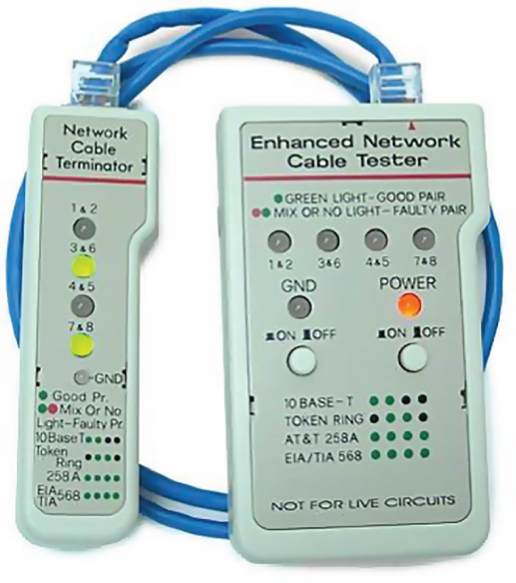
FIGURE 23.1 An inexpensive cable tester
This little box can verify the connection through the cable and tell you if the cable is straight-through or crossover. It can also identify problems such as grounding issues. Sometimes the problem is not a complete lack of connectivity. Sometimes performance is slow, which can also be a cabling issue that a cable tester can identify. This tool is as cheap as they come.
Let's focus on the types of tools available for both copper and fiber-optic cable testing. This is not to say that you need all of the tools listed here. In fact, I'll try to steer you away from certain types of tools. Sometimes you'll get lucky and have the luxury of choosing between high-tech and low-tech devices that perform roughly the same function. You can choose which ones you prefer according to the requirements of your network, your operational budget, even your temperament and time constraints. Some of the tools are extremely complicated and require extensive training to use effectively, whereas others can be used by pretty much anybody equipped with a functioning brain.
Other important considerations to keep in mind when selecting the types of tools that you need are based on the descriptions of cable tests given earlier in this chapter, the test results required by the standards you're using to certify your network, and the capabilities of the people who will be doing the actual work. And don't forget the potentially painful cost of some of them.
Loopback Adapter (Plug)
A loopback adapter can be used to loop an Ethernet interface's transmit back to its receiver. This does not loop the data back on an Ethernet interface. Loopback adapters are only useful to verify that the port's transmit and receive electronics are working. Also, you can insert the loopback adapter at one end of a cable and use a cable tester at the other to verify your cable drop.
A loopback test is a diagnostic procedure in which a signal is transmitted and returned to the sending device after passing through all or a portion of a network or circuit. The returned signal is compared with the transmitted signal to evaluate the integrity of the equipment or transmission path. A computer needs a loopback plug that is inserted into a port in order to perform a loopback test.
Loopback adapters are more useful in the telecom world of T1s and DS0 interfaces where the send traffic will be returned to the receiver for testing.
Loopback plugs are made for both Ethernet and fiber applications. Figure 23.2 shows an Ethernet loopback plug.

FIGURE 23.2 Ethernet loopback plug
Figure 23.3 shows a plug for fiber applications.

FIGURE 23.3 Fiber loopback plug
Wire-Map Testers
A wire-map tester is a device that transmits signals through each wire in a copper twisted-pair cable to determine if it's connected to the correct pin at the other end. Wire mapping is the most basic test for twisted-pair cables because the eight separate wire connections involved in each cable run are a common source of installation errors. Wire-map testers detect transposed wires, opens (broken or unconnected wires), and shorts (wires or pins improperly connected to each other). All of these problems can render a cable run completely inoperable.
Wire-map testing is nearly always included in multifunction cable testers, but sometimes it's just not worth spending serious cash on a comprehensive device. Dedicated wire-map testers that run about $200–$300 are relatively inexpensive options that enable you to test your installation for the most common faults that occur during installation and afterward. If, say, you're installing voice-grade cable, a simple wire-mapping test is probably all that's needed.
A wire-map tester essentially consists of a remote unit that you attach to the far end of a connection and a battery-operated, handheld main unit that displays the results. Typically, the tester displays various codes that indicate the specific type of fault that it finds. You can also purchase a tester with multiple remote units that are numbered so that one person can test several connections without constantly traveling back and forth from one end of the connections to the other to move the remote unit.
Continuity Testers
A continuity tester, or line tester, is an even simpler and less-expensive device than a wire-map tester. It's designed to check a copper cable connection for basic installation problems like opens, shorts, and crossed pairs. It will set you back only a few dollars, but such a device usually can't detect the more complicated twisted-pair wiring faults. It's still a nice option for basic cable testing, especially for coaxial cables that have only two conductors and so don't easily confuse whoever is installing them.
Like a wire-map tester, a continuity tester consists of two separate units that you connect to each end of the cable you want to test. Most of the time, the two units can snap together for storage and easy testing of patch cables. But remember, a continuity tester simply tests continuity, equivalent to data at one bit per minute (or slower), and cannot tell you whether or not a cable will reliably pass Ethernet data at network speeds. For that, you need a real cable tester that can test cables up to Gigabit speeds or higher.
Protocol Analyzer
A protocol analyzer is often confused with a packet sniffer because some products really are both. Remember—a packet sniffer looks at all traffic on a network segment. On the other hand, a protocol analyzer (surprise!) analyzes protocols. These tools come in both software and hardware versions, but compared to sniffer and similar products, a network protocol analyzer is likely to give you more information and help. This is because a bona fide protocol analyzer can actually help you troubleshoot problems, whereas most sniffers just provide information for you to enjoy deciphering.
A network protocol analyzer can perform the following functions:
- Help troubleshoot hard-to-solve problems
- Help you detect and identify malicious software (malware)
- Help gather information such as baseline traffic patterns and network-utilization metrics
- Help you identify unused protocols so that you can remove them from the network
- Provide a traffic generator for penetration testing
- Possibly even work with an IDS
And last, and perhaps most important for you, they can really help you learn about networking in general. This means if you just want to find out why a network device is functioning in a certain way, you can use a protocol analyzer to sniff (there's that word again) the traffic and expose the data and protocols that pass along the wire.
Certifiers
Certification testers—or certifiers—are used to determine whether your network meets specific International Organization for Standardization (ISO) or Telecommunications Industry Association (TIA) standards (Cat 5e, Cat 6, Cat 7, or Cat 8). A certification tester is the only option for you in this case. Also, if your network is wired with both copper and fiber, you really must use a certification tester.
Basically, a certifier is a combination cable tester and network analyzer, only better because it comes with more options. This is wonderful because it makes your job easier and makes you seem smarter to everyone around you—you're only as good as your tools, right? A good certifier will test the performance and response times of network resources like web, file, email, and even DNS and Dynamic Host Configuration Protocol (DHCP) servers. And, at the same time, it will certify your full Category 6 cable installation. After it finishes all this, you can provide your boss with a detailed network test report complete with dazzling, colorful graphics to make it simple to explain and understand—voilà! You're instantly the genius of the day.
To get these smarts, all you need is a lot of money. These products are not for the small office, home office (SOHO) market because they cost literally thousands of dollars, starting at about $5,000.
Time-Domain Reflectometer
A time-domain reflectometer (TDR) is a tool that finds and describes faults in metallic cables like twisted wire pairs and coaxial cables. The equivalent device for optical fiber is an optical time-domain reflectometer (OTDR), which I'll talk about in a minute.
A TDR works in the same basic way that radar does. It transmits a short rise time pulse along the conductor, and if it turns out to be of a uniform impedance and properly terminated, the entire transmitted pulse is absorbed in the far-end termination; no signal is reflected back to the TDR. Any impedance interruptions will cause some of the incident signal to be sent back toward the source, letting you know all is not well.
So basically, any increases in the impedance create a reflection that reinforces the original pulse and decreases the impedance, thereby creating a reflection that opposes the original pulse. The resulting reflected pulse that's measured at the output/input to the TDR is displayed or plotted in measures of time. And because the speed of signal propagation is pretty consistent for a given type of transmission medium, the reading can also tell you about the cable length.
Because of this sensitivity to any variation in impedance, you can use a TDR to verify these things:
- Speed and condition of the cable
- How long it takes to send a signal down a cable and how long it takes to come back
- Cable impedance characteristics
- Splice and connector locations and their associated loss amounts
- Estimated cable lengths
Now, let's take a look at a device that tests fiber-optic cables.
Optical Time-Domain Reflectometer
An optical time-domain reflectometer (OTDR) is an optoelectronic instrument used to give you the skinny on optical fibers, typically referred to as light meters. It works by putting out a series of optical pulses into the specific fiber you want to test. From the same end that sent these impulses, it collects and measures the light that is scattered and reflected along the length of the fiber. It then records the change in the amount of refraction at various points. This is a lot like the way an electronic TDR measures reflections caused by impedance changes in a cable that you're testing. The strength of the return pulses is incorporated into a measure of time, which also conveniently gives you the fiber's length.
We use OTDRs to give us the following information:
- The fiber's estimated length
- Its overall attenuation, including splice and mated-connector losses
- The location faults, such as breaks
Figure 23.4 shows the output from an OTDR testing a fiber connection.

FIGURE 23.4 Sample OTDR output
The spike shows where a splice in the fiber is located, which has resulted in the signal being degraded. This is a very typical output. As the signal attenuates, you see a gradual but quick drop in decibels (dB). Any connector will actually show a reflection, which, as mentioned, shows up as a spike in the OTDR output. The connector then creates more attenuation and loss of more db. The more splices, the less distance you can run with fiber.
Multimeter
A multimeter, or a multitester (also called a volt/ohm meter [VOM]), is a multitasking electronic measuring instrument. Your average multimeter typically includes features like the ability to measure voltage, current, and resistance. Multimeters come in analog and digital versions, and they range from basic handheld devices useful for simple fault-finding and field-service work to more complex bench instruments that will give you measurements with a very high degree of accuracy.
They can be used to troubleshoot electrical problems in a wide array of electrical devices like batteries, motor controls, appliances, power supplies, and wiring systems. Figure 23.5 shows output of the multimeter that I use to help troubleshoot my networks.

FIGURE 23.5 A multimeter
Multimeters come in lots of flavors with different ranges of features and prices. Cheap ones cost less than $10, but the top-of-the-line models can set you back up to $5,000.
Spectrum Analyzer
A spectrum analyzer is a tool that focuses on the physical layer, which will vary based on the type of analyzer. Although vendors make these analyzers for both audio and optical signals, in most cases spectrum analyzers are used to analyze wireless or radio frequency signals. Spectrum analyzers are primarily used to identify and measure the strength of radio signals that are present in the area. They can visually display these signals by frequency on the device. These devices are used to locate sources of interference that may impact the operation of a wireless network. Figure 23.6 is a screenshot of a spectrum analyzer showing the relative use of each channel in the area.
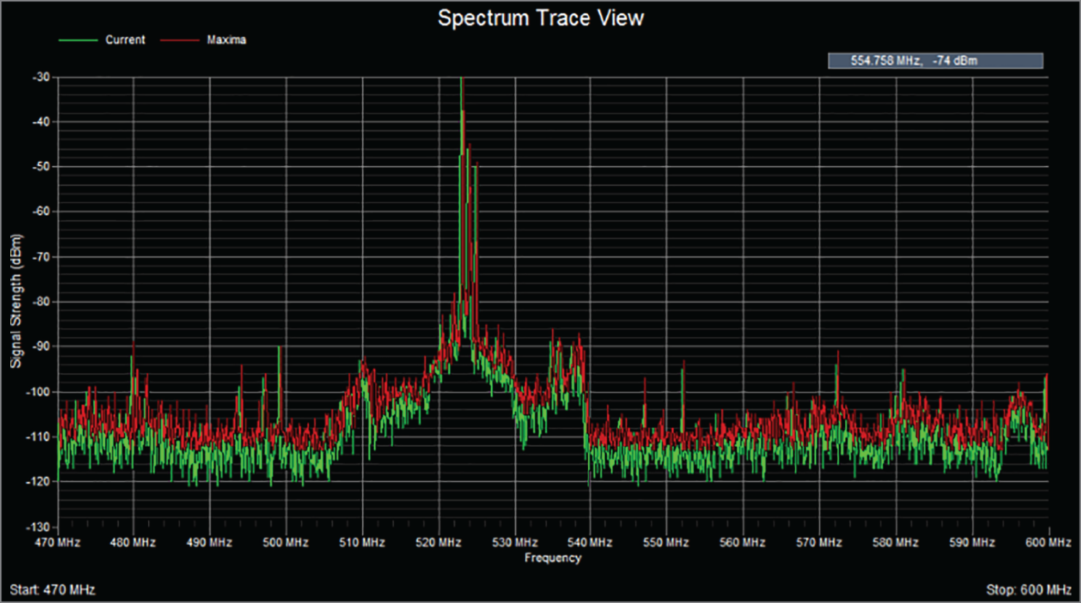
FIGURE 23.6 Spectrum analyzer output
Toner Generator (Probe)
A toner probe, also called a tone generator, is a simple copper cable tester that is simple to use and can be used to trace a wire in a wall. It is a two-piece unit that's basically a tone generator and probe, sometimes called a “fox and hound” wire tracer. This type of device consists of one part that you connect to a cable with a standard jack—or to an individual wire with alligator clips that transmit a signal over the cable or wire—and another part that's a penlike probe that emits an audible tone when it touches the other end of the cable, the wire, or even its insulating sheath.
Most often, you will use a toner probe to locate a specific connection in a punch-down block because (annoyingly) some installers run all the cables for a network to the central punch-down block without labeling them. They (or you, if you're unlucky enough) then have to use a tone generator to identify which block is connected to which wall plate and label the punch-down block accordingly. This tool can identify a particular cable at any point between the two ends, and because the probe can detect the cable containing the tone signal through its sheath, it can help you to locate one specific cable out of a massive cable-spaghetti bundle in a ceiling conduit or other type of raceway.
Just connect the tone generator to one end, and touch the probe to each cable in the bundle until you hear the tone. Figure 23.7 shows a picture of my toner and the probe I use to find the tone on the other end of the cable.

FIGURE 23.7 A toner probe
Also, by testing the continuity of individual wires using alligator clips, you can use a tone generator and probe to find opens, shorts, and miswires. An open wire won't produce a tone at the other end, a short will produce a tone on two or more wires at the other end, and an improperly connected wire will produce a tone on the wrong pin at the other end.
Sound like fun to you? Well, not so much—it takes a really long time, and it's super tedious. Worse, the whole process is almost as prone to errors as the cable installation itself. You have to either continually travel from one end of the cable to the other to move the tone generator unit or use a partner to test each connection, keeping in close contact by using radios or some other means of communication to avoid confusion. So, considering the time and effort involved, investing in a wire-map tester is just a much more practical solution unless you're numbingly bored or really easily amused.
Tap
A tap is a network hardware device that lets you passively insert test equipment in the traffic flow between two devices. This allows you to connect a network traffic analyzer to a third port of a tap that also has two ports that are connected between the two communicating devices. Taps can be used to monitor for intrusions and for packet captures during troubleshooting. Taps are only used for monitoring the data flow in a cable; they are receive only and cannot be used to insert frames into the stream.
Metrics
When using any of the tools discussed in the preceding sections, especially the network testing tools, collecting and comparing metrics over time is a valuable exercise. Once a baseline has been established for these metrics, you can determine when an issue has gotten better or worse over time. It also allows you to determine if measures you have taken to improve a scenario have done so.
Error Rate
One of the key metrics for which a baseline should be established is network error rate. Since network errors typically lead to retransmissions, they also result in reduced throughput because each retransmission represents a lost opportunity to use that time slot to send new data.
Butt Set
A butt set is essentially a portable telephone that allows you to test analog wet or dry lines and is used to monitor those lines. The most common type, shown in Figure 23.8, can both monitor and transmit.

FIGURE 23.8 A butt set
You may see this with telco guys up on the telephone poles. They use their butt sets to connect to telephone lines, test them, and even make phone calls.
Another handy tool that will take the place of a butt set is a hound. This noncanine device is nothing more than an inductively coupled amplifier with a small speaker in a handheld tool. It's used to monitor the audio on a given line to verify that you have the right pair before connecting it and typically used with a toner probe. It will also monitor for noise.
Punch-Down Tool
Most networks today are built using twisted-pair cable of some sort. This cable is usually terminated in wiring closets using a tool known as a punch-down tool. It's called that because that's exactly what the tool does—punches down the wire into some kind of insulation displacement connector (IDC).
There are different types of punch-down tools. The most common is a punch-down with replaceable blades for the different types of connectors (either 66 or 110). Figure 23.9 shows an example of this type of punch-down tool.

FIGURE 23.9 An example of a punch-down tool
IDCs make contact by cutting through, or displacing, the insulation around a single conductor inside a twisted-pair cable.
As shown in Figure 23.10, the punch-down tool pushes a conductor between the sides of a V inside an IDC, in this example a keystone connector, allowing the small metal blade inside the connector to make contact with the inner conductor deep inside the wire.

FIGURE 23.10 Using a punch-down tool on a small keystone connector
Now let's take a look at how to put a cable end together.
Cable Snips/Cutters
A wire crimper, often simply called a crimper, is a handy tool found in most network technicians' tool bags. Crimpers are primarily used for attaching ends onto different types of network cables via a process known as—that's right—crimping. Crimping involves using your hands to apply a certain amount of force to press some kind of metal teeth into the inner conductors of a cable. Before you can crimp a connector onto the end, you've got to strip the cable with a type of cable stripper (or snip) and then properly put the wires into the connector.
Figure 23.11 shows what a cable stripper and snip looks like (this particular tool also includes a crimper).
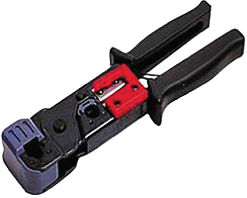
FIGURE 23.11 A combination cable stripper, crimper, and snippers
Often, network technicians will make patch cables with a crimper. They'll take a small piece of Category 5e, 6, 7, or 8 unshielded twisted-pair (UTP), strip the cable, and crimp two RJ-45 ends onto it to create the cable. Snips will create the type of cable needed to connect a host to a wall jack connection, for example. There are strippers and crimpers for the other types of cable as well—even specialized crimpers for fiber-optic ends.
Voltage Event Recorder (Power)
Alternating current (AC) is basically the food that PCs and other network devices require in specific amounts to function properly. In the United States, it's normally 110 volts and changes polarity 60 cycles a second (60 hertz). These values are referred to as line voltage. Any deviation from these values can create some major problems for your PC or other electronics—like death. While we're on the subject, you should also know that when a telephone rings, the phone company central office puts 140 VAC on the line to ring that bell; telephone lines are not always the “low-voltage” devices we think they are. Do all phone systems do this, even PBX systems within buildings? Are you willing to bet your life that they don't? Didn't think so.
This is why we have surge protectors. These little saviors use a special electronic circuit that monitors the incoming voltage level and trips a circuit breaker when the voltage level reaches critical mass, which is known as the overvoltage threshold. Even though having a surge protector is definitely better than nothing, they too can fall victim to overvoltage events—I'm reminded of a friend whose home was struck by lightning during a thunderstorm and he found his surge protectors literally melted into the carpet! But they're still cool because even though they're really only somewhat protective, they are multiple-outlet strips that give us a lot more places to plug in our stuff.
By contrast, a quality voltage event recorder can troubleshoot and even provide preventative maintenance on your entire electrical system, whether it's for a home or a huge factory. Although they do big things, they're typically small devices that just plug into a wall and record, over time, the power quality of a given circuit. You would typically use a voltage event recorder for the following applications:
- Recording Voltage The voltage event recorder monitors and records the supply voltage and checks whether the socket outlet is providing voltage within specifications.
- Measuring Distortion The device measures frequency and harmonics, and it checks whether your uninterruptible power supply (UPS) system is functioning correctly.
- Measuring Flicker It checks the switching loads on lighting systems.
- Capturing Voltage Transients It can help you find intermittent, momentary events that may be affecting your equipment; the full waveform is captured with date, time stamp, and duration.
But you still have to do more to ensure the vitality of your electronic devices because they're very sensitive to temperature as well. This means you also need a way to monitor the temperature of the place(s) where your equipment is stored.
Fiber Light Meter
Some fiber-optic transmitters use LEDs as the source while more advanced and long-distance fiber types use lasers. Lasers can damage your eyesight, and it is best to never look directly at a fiber cable to see if there is light. A fiber light meter can tell you the receive levels and wavelengths to test and verify your fiber cable runs.
Fiber Fusion Splicer
When two fiber cables need to be spliced, a fusion splicer fuses the two cables together and minimizes the light scattering or being reflected back in the cable. They also ensure that the splice is strong and resistant to separation.
Summary
You need network tools, and you need to know how to use them. And as I said, you can get your hands on many of them for free, so download them and use them as soon as possible to get the experience you'll need to pass the CompTIA Network+ exam.
This chapter covered network scanners. I also covered hardware tools, which are rarely free. The good news is that you don't need many of them yourself, but the company that owns all the equipment definitely does. Even though I've used all of the tools I talked about in this chapter, I don't own most of them personally—only the ones that are free or relatively inexpensive.
In the hardware tools section, I covered cable testers, analyzers, certifiers, TDR/OTDRs, and other critical tools that help you test the cables and devices in your network, monitor them, and keep them up and running smoothly.
Exam Essentials
- Understand what network scanners are and how to use each one. Packet sniffers, IDS/IPS software, and port scanners are all network scanners. These devices can help you both troubleshoot and fix your network as well as find and stop hackers in their tracks.
- Remember the basic purpose of a packet sniffer. The basic purpose of packet sniffers or network analyzers is to collect and analyze each individual packet that is captured on a specific network segment to determine if problems are happening.
- Understand what an OTDR is used for. An optical time-domain reflectometer (OTDR) is an optoelectronic instrument used to test fiber-optic cabling. You can learn the cable's estimated length and attenuation (loss in dB) and the location of faults.
- Understand the difference between cable testers and certifiers. Cable testers simply tell you if the cable will function. Cable certifiers run much more sophisticated tests that determine if the cable performs according to specifications called for in the standard.
- Understand the value of temperature and humidity monitors. These devices can monitor environmental conditions and alert you if either the temperature or the humidity in a server room or area falls below or rises above the prescribed range of safe values.
Written Lab
You can find the answers to the written labs in Appendix A. Answer the following questions about software and hardware tools.
- True/False: A tap can be used to insert data into a link between two devices.
- True/False: A crossover cable is needed between two directly connected PCs.
- True/False: Plenum cables can be installed in air-conditioning ducts.
- True/False: An OTDR is used to test fiber connections.
- True/False: A network analyzer will see every packet on every segment of your network at the same time.
- What type of device determines if a cable meets standards specifications?
- True/False: It is okay to scan the DoD network servers with a port scanner.
- You need to monitor the temperature of your server room. What device should you use?
- You want to monitor your UPS systems and make sure they are functioning correctly. What device should you use?
- What type of device is used to put an RJ-45 end on a Cat 5e, 6, 7, or 8 cable?
Review Questions
You can find the answers to the review questions in Appendix B.
- Which is a tool in the network scanner category? (Choose all that apply.)
- Packet sniffers
- IDS/IPS software
- Port scanners
- None of the above
- What is the purpose of packet sniffers?
- Discarding frames
- Sending transmissions from one port to another port
- Looking inside every packet on a network segment
- Stopping malicious behavior on the network
- You need to trace cables in multiple-pair wiring. What tool will you use?
- Toner probe
- Cable stripper/snips
- Cable tester
- Butt set
- What tool would you use to both find a break in a fiber-optic connection and test the fiber connectivity on the network?
- Multimeter
- OTDR
- Butt set
- Toner probe
- You need to create a cable that will connect your host to a wall jack connection. Which of the following will you use?
- IDS/IPS
- Snips
- Coax cable strippers
- Multimeter
- End-to-end loss across an Ethernet cable is called ___________________.
- Degradation
- Attenuation
- Runts
- Spectrum loss
- What is the purpose of a port scanner?
- Scan UDP for closed ports
- Sweep TCP for closed ports
- Search the network host for open ports
- Validate operations
- What is the purpose of wire-map testers?
- Check copper cable for crossed pairs only
- Analyze protocols in software
- Help find unused protocols and remove them from the network
- Detect transposed wires, opens, and shorts in twisted-pair cables
- Which of the following can check the speed and condition of the signal on a cable, measure the time it takes to send a signal down the wire and back, and find the exact location of a break?
- Multimeter
- TDR
- Tone generator
- Event recorder
- Which device should be used if you need to determine whether your network meets ISO or TIA standards?
- Angry IP
- Certifiers
- Nmap
- Routing table
- Which software tool is used to view network traffic at the frame level?
- TDR
- Multimeter
- Port scanner
- Packet sniffer
- Which of the following options is not a function of a TDR?
- Estimate cable lengths
- Find splice and connector locations and their associated loss amounts
- Display unused services
- Determine cable-impedance characteristics
- Send a signal down a cable and measure how long it takes to come back
- Which device would be used to measure voltage?
- Multimeter
- OTDR
- Butt set
- Toner probe
- Which device would most likely be used to locate a specific connection in an unlabeled punch-down block?
- VOM
- Certifier
- TDR
- Toner probe
- Which tool would be used to connect wire between two punch-down block blades?
- Punch-down tool
- Crimper
- Snips
- Strippers
- Which tool is used to attach an RJ-45 connector to a Cat 5e, 6, 7, or 8 cable?
- Punch-down tool
- Crimper
- Snips
- Strippers
- On which of the following would a technician use a punch-down tool?
- RJ-45 connector
- CSU/DSU
- 110 block
- Fiber ST connector
- Which device monitors incoming voltage levels and overvoltage thresholds?
- Repeater
- Toner probe
- VOM
- Surge protector
- Which of the following tools can test a port on a device?
- Cable certifier
- Loopback plug
- Butt set
- Toner probe
- You install new switches in your server room and are now experiencing network instability and other issues across all servers in the rack. Which device would be used to alert you of a system overheating?
- Voltage event recorder
- Temperature monitor
- Surge protector
- Probe