
11
Security Schemes for AMI Private Networks
In this chapter, a security protocol is proposed specifically for the advanced metering infrastructure (AMI) in the smart grid to address the security requirements. Although AMI does not cover all private networks in smart grid communications, security protocols for its comprehensive and complicated infrastructure can be extended to other private networks based on their different security requirements. The proposed security protocol will be illustrated in four parts, namely the initial authentication scheme, secure uplink transmission scheme, secure downlink transmission scheme, and domain secret update scheme.
11.1 Preliminaries
The proposed security schemes in this chapter are based on several network security concepts: for example, security services, security mechanisms, etc. To make the illustration clearer, we first present some basic background about network security in this section.
11.1.1 Security Services
Security services are provided in a system design to protect against possible security attacks. In a communication system, possible security services are described in Table 11.1
Table 11.1 Security services.
| Security service | Description |
| Access control | Control access from authorized users to resources. |
| Authentication | Verify the identities of entities. |
| Confidentiality | Ensure that information is accessible only to authorized entities. |
| Data integrity | Maintain the accuracy and completeness of data. |
| Non‐repudiation | Prove the data origin. |
| Availability | Make information available to authorized entities when needed. |
For a given communication system, whether to apply a security service depends on system requirements. The system may be most secure if all security services are applied. However, due to limited computational resources, it is impractical to implement all services.
11.1.2 Security Mechanisms
Security mechanisms are the tools to achieve security services in a communication system. Some major security mechanisms include encipherment, authentication, access control, digital signature, and data integrity.
Encipherment mechanisms mainly provide confidentiality. Encipherment algorithms include reversible and irreversible ones. Reversible encipherment algorithms are widely known as encryption algorithms, which are divided into symmetric and asymmetric ones.
- A symmetric encryption is also known as private‐key encryption. It is an encryption algorithm that is based on a preshared secret key. Both communication entities can perform the same function, either encryption or decryption, using the same process. In this chapter, a symmetric encryption algorithm is denoted as
 , where
  is the preshared secret key and
  is the input message. The decryption algorithm is denoted as
  correspondingly.
 - An asymmetric encryption algorithm is also known as public‐key encryption. In an asymmetric algorithm, each communication entity has two keys, public and private respectively. The public keys are shared with the other communication entities, whereas the private keys are kept secret. A message encrypted with the public key must be decrypted by its paired private key. A message signed with the private key must be verified by its paired public key. Therefore, the two communication entities are not symmetric.
- Irreversible encipherment algorithms are not used for encryption. Those algorithms may or may not depend on a key. They are mostly applied to other services, for example, data integrity and digital signatures.
Encipherment mechanisms are widely applied to achieve other security mechanisms.
Authentication mechanisms are applied to authentication services. Instead of specific algorithms, authentication mechanisms are mainly handshake protocols with messages created by other mechanisms using unique information provided by entities.
Access control mechanisms are applied to control access to services. Similar to authentication, many access control mechanisms use handshake protocols to determine and enforce the access rights of an entity depending on its authenticated identity.
Digital signature mechanisms are applied to non‐repudiation services and sometimes to data integrity. Most digital signature mechanisms are based on public‐key encryption algorithms, where the sender signs a message with the private key and the receiver verifies the signature with the sender's public key.
Data integrity mechanisms are applied to data integrity services. Irreversible encipherment algorithms are applied as data integrity mechanisms in most communication systems. For example, hash functions are data integrity mechanisms. In this chapter, a hash function is defined as ![]() . Note that a hash function has no key, so any entity has the ability to generate and verify a hash code with a given message.
. Note that a hash function has no key, so any entity has the ability to generate and verify a hash code with a given message.
Note that security mechanisms are not a one‐to‐one match with security services. A security service may be provided by multiple security mechanisms, and a security mechanism may be applied to multiple security services.
11.1.3 Notations of the Keys Used in This Chapter
For simplicity, the notations of the keys used in the proposed security protocol of this section are listed in Table 11.2.
Table 11.2 Notations of the keys.
| Keys for symmetric algorithms | |
| Preshared secret key for node | |
| Active secret key for node | |
| Session key between | |
| Keys for asymmetric algorithms | |
| Public key for node | |
| Private key for node | |
| Public key for the authentication server | |
| Private key for the authentication server | |
11.2 Initial Authentication
11.2.1 An Overview of the Proposed Authentication Process
In this section, we present the initial authentication of the security scheme. The security scheme is proposed mainly for the wireless networks in the AMI. Security in the backbone network can be achieved using existing mechanisms and protocols controlled by utilities. Nodes in the wireless networks mainly include data aggregate points (DAPs) and smart meters.
11.2.1.1 DAP Authentication Process
Before joining the AMI, a DAP must be authenticated through the initialization process [167]. Assume that utilities have full control of their private networks; thus an authentication server (AS) is managed by utilities on their side. The initial authentication is based on a trusted AS. Generally speaking, if a node is closer to the AS, it will be authenticated before those that are farther away due to multihop networks. Therefore, before a smart meter joins the AMI, the gateway DAPs and normal DAPs are initialized by the AS. Note that gateway DAPs are initialized before normal DAPs since they have direct communication to the concentrator. For simplicity, gateway DAPs are not specified in the rest of the discussion.
DAPs are divided into two groups: one active and the other uninitialized. An active node is a node that has been authenticated by the AS to join the AMI communication system and is functioning normally. An uninitialized node can be one of the following four types:
- A newly installed node
- A node that has recovered from a malfunction
- A node updated with new preshared keys
- A node reinstalled to another location
The authentication process for uninitialized nodes is carried by existing active nodes and the AS. For example, as illustrated in Figure 11.1, DAP ![]() is uninitialized, while its neighboring DAPs
is uninitialized, while its neighboring DAPs ![]() ,
, ![]() and
and ![]() are active. To join the AMI,
are active. To join the AMI, ![]() initiates the authentication process by broadcasting a request to all of its active neighbors, which will relay the request to the AS through established secure links.
initiates the authentication process by broadcasting a request to all of its active neighbors, which will relay the request to the AS through established secure links.
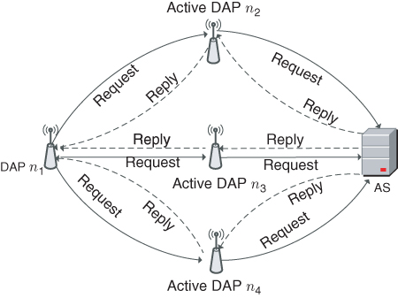
Figure 11.1 Initial authentication process for DAP  .
.
After the authentication process is performed by the AS, ![]() will receive reply messages from the AS through its active neighbors. The reply messages are different from each other, since they consist of authentication confirmation as well as information to establish secure links between
will receive reply messages from the AS through its active neighbors. The reply messages are different from each other, since they consist of authentication confirmation as well as information to establish secure links between ![]() and each of its active neighbors. In summary, the initial authentication process accomplishes the following three tasks:
and each of its active neighbors. In summary, the initial authentication process accomplishes the following three tasks:
 is authenticated to become an active node and join the AMI
 establishes a secure connection to the AS through one of its active neighbors that has the shortest distance to the AS
 establishes backup secure connections to the AS through the rest of its active neighbors
11.2.1.2 Smart Meter Authentication Process
After all DAPs have been initialized by the AS, a neighborhood‐area network is formed in the AMI. Smart meters will then be initialized through active DAPs. Unlike DAPs, smart meters do not have many neighbor nodes because of two reasons. First, smart meters have a limited transmission range. They are unlikely to have a direct connection with more than one DAP. Second, it is not a good idea to let smart meters communicate with each other, since their data contains much private information and smart meters are easier to access than DAPs.
An overview of the initialization process for a smart meter is shown in Figure 11.2. An uninitialized smart meter sends a request to an active DAP, and the DAP will relay the request to the AS through a secure communication link. Once the authentication process is approved by the AS, a reply is sent to the smart meter through the active DAP.

Figure 11.2 Initial authentication process for a smart meter.
11.2.2 The Authentication Handshake Protocol
Without loss of generality, the authentication handshake protocol is presented according to the example given in Figure 11.1, where ![]() is the uninitialized node. One of its active neighbor
is the uninitialized node. One of its active neighbor ![]() is chosen to illustrate the detailed initialization process. The initialization processes through active neighbors
is chosen to illustrate the detailed initialization process. The initialization processes through active neighbors ![]() and
and ![]() are similar.
are similar.
In practice, the active neighboring node ![]() may not have a direct connection to the AS. Instead, there may be a secure link established between
may not have a direct connection to the AS. Instead, there may be a secure link established between ![]() and the AS. Therefore, we focus on
and the AS. Therefore, we focus on ![]() ,
, ![]() , and the AS in the process. Note that other active nodes in the same secure link do not store useful information from the process. The initialization process achieves three mutual authentications.
, and the AS in the process. Note that other active nodes in the same secure link do not store useful information from the process. The initialization process achieves three mutual authentications.
- Authentication between
 and the AS: This mutual authentication is straightforward, since the AS will only allow legitimate nodes to join the AMI and the nodes will also trust only the AS.
 - Authentication between
 and the AS: This mutual authentication is intended to ensure that
  is active and is trusted to relay the request from
  .
. - Authentication between
 and
and  : This mutual authentication between
  and
and  is to help establish further secure communications from
  to
to  .
.
Each legitimate node, whether uninitialized or active, has a preshared secret key (i.e. ![]() for node
for node ![]() ) with the AS. Besides, an active secret key is assigned to each active node (e.g. key
) with the AS. Besides, an active secret key is assigned to each active node (e.g. key ![]() ) for node
) for node ![]() , mainly for uplink data traffic encryption. This active secret key is also used by the AS to verify if this node is active or not. Similar to
, mainly for uplink data traffic encryption. This active secret key is also used by the AS to verify if this node is active or not. Similar to ![]() ,
, ![]() is known only to
is known only to ![]() and the AS. In order to establish a secure connection from
and the AS. In order to establish a secure connection from ![]() to the AS after the authentication process, an active secret key
to the AS after the authentication process, an active secret key ![]() must be generated by the AS and assigned to
must be generated by the AS and assigned to ![]() during the initialization process. Note that
during the initialization process. Note that ![]() does not carry
does not carry ![]() before initialization process; only
before initialization process; only ![]() is known to
is known to ![]() . Moreover, although the active nodes relay messages from the AS to
. Moreover, although the active nodes relay messages from the AS to ![]() , the keys are not disclosed to those intermediate nodes.
, the keys are not disclosed to those intermediate nodes.
The authentication handshake protocol is initiated from the uninitialized node ![]() . The entire process includes six handshakes among
. The entire process includes six handshakes among ![]() ,
, ![]() , and the AS, as shown in Figure 11.3. The 6 messages exchanged during the process are described as follows:
, and the AS, as shown in Figure 11.3. The 6 messages exchanged during the process are described as follows:
 . To initiate the process,
  sends
sends  to the AS through
  . In message
  ,
,  is a cryptographic hash function, ‘
 ’ is an XOR function, and
  is a time stamp. The authentication is achieved by
  , since with given
  and
and  , the AS is the only entity other than
  able to compute
  .
. . Once
  receives the request message
  , it generates
  and sends the new message to the AS. In
  ,
,  is a symmetric encryption function with key
  . In particular, the active key for
  is applied to the encryption. Another time stamp
  is generated at
  and included in
  together with its own identity
  . Then,
  encrypts the entire message with
  . The encryption protects
  from being disclosed to other active nodes in the secure link. An identity verification code
  is generated at
  . The extra information generated at
  is used for the AS to authenticate
  as an active node and validates the freshness of the message.
 . Once the AS receives
  , it authenticates
  by decrypting
  using
using  . Time stamp
  is verified by comparing a computed
  to the received value. Then, the AS authenticates
  by computing
  . Once
  is authenticated, the AS generates a message
  for
for  . In
. In  ,
,  is the initial vector for further uplink transmission, and
  is the active key for
  .
.  is the public key of the AS for downlink transmission security protocols. Moreover,
  is the generating parameter for public‐key cryptography in the communication domain. Parameter
  can be a set of parameters depending on the chosen public‐key cryptographic schemes. For example,
  can be two primes numbers if RSA [187] is applied and have more parameters if identity‐based cryptography [188, 184, 185] is applied. Nonetheless,
  remains the same in the communication domain. Although the AS generates
  , it does not generate public/private keys for each node. It is better to keep the nodes as independent as possible from other nodes and the AS. Unique information for
  is encrypted with the preshared secret key
  , that is,
  . Moreover, in
  ,
,  is for integrity validation. Note that
  is also part of the input for
  to authenticate
  through the AS. Then the AS generates another time stamp
  (it is possible that
  ) and
) and 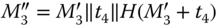 . Finally, the message sent back to
  is
is  .
. . Once message
  reaches
  ,
,  first reveals
  by decrypting the message and verifies data integrity by computing
  . At this point,
  has authenticated
  from the AS. Then,
  forwards
  to
to  together with the public key
  . A time stamp
  is generated at
  for message freshness. Hash value
 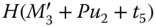 is computed for data integrity of message
  .
.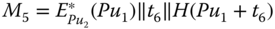 . Once
  receives
  , it reveals
  ,
,  ,
,  , and
, and  by decrypting
  . After verifying the integrity of the received information,
  successfully authenticates
  . Then
  generates a pair of public/private keys based on a given public domain secret
  . The public key
  is encrypted with the public key of
  so that
  , where
  is the encryption function of the adopted public key cryptography. A time stamp
  is generated, and
  is computed at
  to provide data integrity for message
  .
. . After exchanging public keys
  and
and  , active nodes
  and
and  can find a way to generate the session key
  for further communication. Session key
  is shared only between
  and
and  . It is refreshed frequently.

Figure 11.3 Detailed initial authentication process through one active neighbor.
After the six handshakes, ![]() is fully initialized, and it joins AMI communications through
is fully initialized, and it joins AMI communications through ![]() . The initial authentication processes through other active neighbors (i.e.
. The initial authentication processes through other active neighbors (i.e. ![]() and
and ![]() in this example) are similar. In particular, the AS sends back the same
in this example) are similar. In particular, the AS sends back the same ![]() ,
, ![]() ,
, ![]() , and
, and ![]() . Note that the preshared secret key
. Note that the preshared secret key ![]() is unique, depending on active neighbor identity
is unique, depending on active neighbor identity ![]() . Nonetheless, in the final handshake,
. Nonetheless, in the final handshake, ![]() will send the same
will send the same ![]() to its active neighboring node
to its active neighboring node ![]() encrypted with
encrypted with ![]() ,
, ![]() in this example. By doing so,
in this example. By doing so, ![]() shares the same public key to all of its active neighbors. Therefore,
shares the same public key to all of its active neighbors. Therefore, ![]() is able to join the uplink transmission through any of the active neighbors. In other words, both operating and backup secure communication channels are established through the initial authentication process.
is able to join the uplink transmission through any of the active neighbors. In other words, both operating and backup secure communication channels are established through the initial authentication process.
The detailed process for smart meter initialization is the same as DAP initialization. The only difference is that, there is one process only because of the single active DAP a smart meter is connected to. The illustration is not repeated here.
11.2.3 Security Analysis
The security of the proposed authentication process is described in terms of each security service, including confidentiality, data integrity, non‐repudiation, and availability. Note that the security services mentioned here are just those for the authentication process, not for the overall security protocol.
- Confidentiality. Confidentiality of the authentication request is not necessary; therefore, it is not provided via specific mechanisms. Much information is transmitted in clear text. Note that the initial authentication request is protected with confidentiality once it reaches an active node in the AMI.
- Data integrity. All the messages (except for
 ) are provided a hash value specifically for an integrity check. Moreover, the input is not the original message, which can easily be captured by an eavesdropper. The input is the XORed messages of the useful information, which cannot be captured or forged. Therefore, the messages in this protocol is cannot be forged. Moreover, with time stamps being applied in each message, a replay attack is unlikely to succeed in the process. The detailed process of
  is not given in this protocol, because the real application may vary based on different public key cryptographic schemes. With a given public key cryptographic scheme, data integrity can be provided in a similar way for session key
  in
in  .
. - Non‐repudiation. The initialization process does not use a digital signature for sender authentication except for
 . However, secret preshared keys are applied for message encryption. With the sender and the receiver being the only entities that can encrypt and decrypt the message, non‐repudiation is achieved for all messages (except for
  ) with symmetric encryption. Non‐repudiation of
  is indeed provided by a digital signature.
 - Availability. Availability of the process is guaranteed as long as the AMI has a wireless connection. The proposed authentication process has enhanced availability through the participation of all active nodes that are neighbors of an uninitialized one.
11.3 Proposed Security Protocol in Uplink Transmissions
In the uplink transmission, data from each node is aggregated in a chain topology and is finally delivered to the service provider (assuming that the AS and the service provider share the same entity). As discussed before, data confidentiality and data integrity are critical requirements for metering data, since any mistakes may cause inefficient grid operation. Sender authentication or non‐repudiation may be considered in certain situations if there are enough computational resources. To achieve all these requirements, we propose the following security protocol for data aggregation in uplink transmission.
11.3.1 Single‐Traffic Uplink Encryption
We first present the uplink encryption process for a single‐traffic transmission. The following description is based on the illustration shown in Figure 11.4. Suppose the single‐traffic transmission follows a path with ![]() nodes in the order of
nodes in the order of ![]() .
.
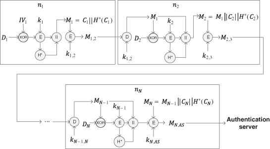
Figure 11.4 Data aggregation process in an uplink transmission.
As the first one of the aggregation, ![]() mixes its raw data
mixes its raw data ![]() with
with ![]() as
as ![]() . It then encrypts the intermediate message with the active secret key
. It then encrypts the intermediate message with the active secret key ![]() as follows:
as follows:
A hash value is generated as ![]() , where
, where ![]() is a hashed message authentication code function that provides data integrity. The notation with
is a hashed message authentication code function that provides data integrity. The notation with ![]() is to distinguish the hash function from the one applied to the initialization process, since different hash functions can be used in authentication and uplink encryption. The hash value is attached to the cipher text as follows:
is to distinguish the hash function from the one applied to the initialization process, since different hash functions can be used in authentication and uplink encryption. The hash value is attached to the cipher text as follows:
Finally, ![]() encrypts the entire message with
encrypts the entire message with ![]() as follows:
as follows:
The next node ![]() first decrypts the incoming data with the session key as follows:
first decrypts the incoming data with the session key as follows:
Then ![]() mixes its raw data
mixes its raw data ![]() with
with ![]() and generates cipher text
and generates cipher text ![]() as follows:
as follows:
A hash value is generated as ![]() and attached to the cipher text. The message from
and attached to the cipher text. The message from ![]() is aggregated to the current message as follows:
is aggregated to the current message as follows:
Finally, ![]() encrypts the entire message with
encrypts the entire message with ![]() as follows:
as follows:
Any intermediate node ![]() performs the same process as
performs the same process as ![]() by replacing indexes
by replacing indexes ![]() with
with ![]() respectively. The final message reaching the AS (or utilities) from node
respectively. The final message reaching the AS (or utilities) from node ![]() is
is ![]() .
.
11.3.2 Multiple‐Traffic Uplink Encryption
A node may receive multiple items of data traffic in the AMI communications network. In this case, the intermediate shall process all incoming traffic and generate a single item for the next node. The example shown in Figure 11.5 is used to illustrate the multiple‐traffic uplink encryption process. Suppose an intermediate node ![]() has two incoming items in traffic from nodes
has two incoming items in traffic from nodes ![]() and
and ![]() respectively;
respectively; ![]() chooses one of them randomly, for example, message
chooses one of them randomly, for example, message ![]() from node
from node ![]() . Node
. Node ![]() processes
processes ![]() by following the single‐traffic uplink encryption as illustrated in the previous subsection and generates a cipher text as follows:
by following the single‐traffic uplink encryption as illustrated in the previous subsection and generates a cipher text as follows:
A hash value ![]() is generated based on the cipher text. The other message
is generated based on the cipher text. The other message ![]() from node
from node ![]() is decrypted at node
is decrypted at node ![]() to reveal
to reveal ![]() . The disclosed
. The disclosed ![]() is flagged such that
is flagged such that ![]() and attached to the cipher text
and attached to the cipher text ![]() . The generated message
. The generated message ![]() at node
at node ![]() is as follows:
is as follows:
The message sent from ![]() to the next node is computed as follows:
to the next node is computed as follows:
If there are more items in incoming traffic, they will be processed as ![]() at node
at node ![]() .
.
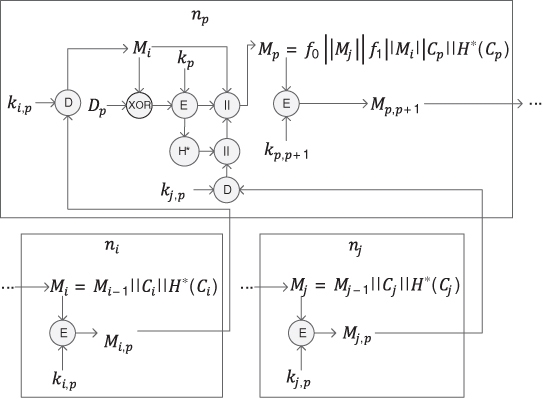
Figure 11.5 Multiflow data aggregation process.
11.3.3 Decryption Process in Uplink Transmissions
Once the AS receives the aggregated data, it starts the decryption process of the data. For example, as shown in Figure 11.6, the AS first authenticates the incoming node, for example, node ![]() , by decrypting the receiving data with the preshared public key
, by decrypting the receiving data with the preshared public key ![]() as follows:
as follows:
and reveals ![]() ,
, ![]() and
and ![]() . The AS then verifies the data integrity by computing the hash value
. The AS then verifies the data integrity by computing the hash value ![]() . As shown in Figure 11.7, if the hash value matches the one disclosed from the decryption, then data integrity is validated. If a hash value cannot be validated, then the data integrity of that message is violated, and the message is discarded. Once data integrity is validated, the AS continue the data recovery process by decrypting
. As shown in Figure 11.7, if the hash value matches the one disclosed from the decryption, then data integrity is validated. If a hash value cannot be validated, then the data integrity of that message is violated, and the message is discarded. Once data integrity is validated, the AS continue the data recovery process by decrypting ![]() as follows:
as follows:
With ![]() already disclosed,
already disclosed, ![]() from node
from node ![]() can be recovered. After that, the AS continues the recovery process with
can be recovered. After that, the AS continues the recovery process with ![]() . Note that the AS does not verify senders other than
. Note that the AS does not verify senders other than ![]() ; thus
; thus ![]() is processed using the same process used to process
is processed using the same process used to process ![]() . To recover
. To recover ![]() , the AS maintains synchronization of the initial vector
, the AS maintains synchronization of the initial vector ![]() .
.

Figure 11.6 Data recovery process in uplink transmission.
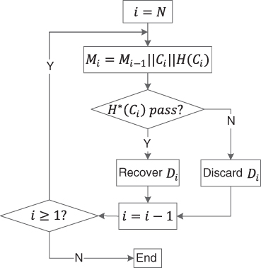
Figure 11.7 Data integrity check in uplink transmission.
If the message includes data from multiple incoming traffic streams, the AS extracts the messages between flags ![]() and
and ![]() and continues to recover the data by following the same process discussed before for
and continues to recover the data by following the same process discussed before for ![]() . The AS may process multiple incoming messages in parallel, as they are not mixed together.
. The AS may process multiple incoming messages in parallel, as they are not mixed together.
11.3.4 Security Analysis
Confidentiality, data integrity, and non‐repudiation are the security services to be provided in the uplink transmission encryption protocol.
- Confidentiality. Confidentiality is achieved in two steps. First, the raw data
 from node
  is mixed with the incoming data from the previous node, that is,
  . The first node achieves this step by mixing its data with the initial vector given by the AS. In addition, the mixed data is encrypted with the active key
  .
. - Data integrity. The data integrity of each message is provided by a hash value generated from that message. The message
 from of
  is cannot be forged unless its active key
  is compromised.
 - Non‐repudiation. Non‐repudiation is provided in two aspects. Within one‐hop transmission, a message
 is encrypted by the preshared secret key
  that is known only to nodes
  and
and  . Thus non‐repudiation is provided to sender
  . At the AS, messages
  for all nodes are encrypted with their active key
  ; thus sender authentication is provided.
11.4 Proposed Security Protocol in Downlink Transmissions
The downlink transmission involves control messages from the service provider to the nodes. Most of the control messages (e.g. price and tariff information) are for all the smart meters in the neighborhood. For those messages, confidentiality may not be as important as it is for the uplink transmission data. Nonetheless, data integrity is important. Message manipulation would alter demand response in the smart grid and in the end result in grid inefficiency. Moreover, non‐repudiation is critical for such control messages so that the customers can trust the sender. Some control messages are one‐to‐one, such as on‐off switch commands for participating customers' air conditioners. Confidentiality must be provided to those messages in addition to data integrity and non‐repudiation.
11.4.1 Broadcast Control Message Encryption
Encryption for a broadcast control message (e.g. ![]() ) is illustrated in Figure 11.8. A time stamp
) is illustrated in Figure 11.8. A time stamp ![]() is appended to the message, and a hash value is generated as
is appended to the message, and a hash value is generated as ![]() , where
, where ![]() is a cryptographic hash function. The hash value is signed by the AS using its private key, such that
is a cryptographic hash function. The hash value is signed by the AS using its private key, such that ![]() , where
, where ![]() is an encryption function using public key cryptography. The broadcast message to each node includes the original control message, time stamp, and the digital signature, such that,
is an encryption function using public key cryptography. The broadcast message to each node includes the original control message, time stamp, and the digital signature, such that,

Figure 11.8 Encryption of broadcast control message  .
.
At the receiver side, the original information (i.e. ![]() and
and ![]() ) is in clear text. The digital signature is decrypted using the public‐key of the AS by performing
) is in clear text. The digital signature is decrypted using the public‐key of the AS by performing ![]() , where
, where ![]() is a decryption function using public key cryptography. The decrypted information is the hash value. The receiver shall compute the hash value at its side and compare the result with the decrypted value to verify data integrity. If the hash value is valid, then non‐repudiation is also validated. If the integrity check is not passed, the receiver will request a retransmission from the AS through its secure uplink transmission tunnel. This rarely happens unless the message is not legitimate. Because each node will receive multiple copies of the control message from all of its active neighbors, if one of the messages is valid, then a retransmission will not be necessary.
is a decryption function using public key cryptography. The decrypted information is the hash value. The receiver shall compute the hash value at its side and compare the result with the decrypted value to verify data integrity. If the hash value is valid, then non‐repudiation is also validated. If the integrity check is not passed, the receiver will request a retransmission from the AS through its secure uplink transmission tunnel. This rarely happens unless the message is not legitimate. Because each node will receive multiple copies of the control message from all of its active neighbors, if one of the messages is valid, then a retransmission will not be necessary.
11.4.2 One‐to‐One Control Message Encryption
Encryption for a one‐to‐one control message (e.g. ![]() ) is illustrated in Figure 11.9. The message is XORed to a time stamp
) is illustrated in Figure 11.9. The message is XORed to a time stamp ![]() and encrypted using the active key
and encrypted using the active key ![]() . A hash value of the encrypted data is generated and signed. Finally, the encrypted data, time stamp, and the digital signature are aggregated together as message
. A hash value of the encrypted data is generated and signed. Finally, the encrypted data, time stamp, and the digital signature are aggregated together as message ![]() such that
such that
Unlike ![]() ,
, ![]() is sent through all of its active neighbors of
is sent through all of its active neighbors of ![]() only, as illustrated in Figure 11.10. A few copies of the information would increase the reliability of transmissions.
only, as illustrated in Figure 11.10. A few copies of the information would increase the reliability of transmissions.
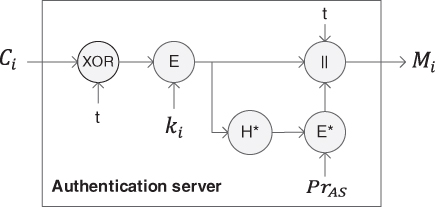
Figure 11.9 Encryption of control message  for
for  .
.

Figure 11.10 Example of control message  to
to  .
.
11.4.3 Security Analysis
Security services provided to broadcast messages and one‐to‐one messages in downlink transmissions are slightly different.
- Confidentiality. For downlink broadcast messages, confidentiality is not provided. For one‐to‐one messages to a specific node (e.g.
 ), confidentiality is provided by encrypting the message with the active key
  .
. - Integrity. Both the broadcast and unicast control messages are cannot be forged, since the corresponding hash values are signed by the AS using its private key.
- Non‐repudiation. Since the hash value of each control message is signed by the AS, the control message is protected against repudiation.
11.5 Domain Secrets Update
In order to keep the AMI secure in the long run, domain secrets need to be refreshed frequently, for example, daily or hourly depending on requirements.
11.5.1 AS Public/Private Keys Update
For the AS, its public and private keys need to be refreshed. After the AS generates a new pair of public/private keys (i.e. ![]() /
/![]() ), it transmits the public key to all the active nodes using the encryption scheme for broadcasting, such that
), it transmits the public key to all the active nodes using the encryption scheme for broadcasting, such that
The update of ![]() is for all the active nodes in the same time slot. In the mean time, separate control messages signed by
is for all the active nodes in the same time slot. In the mean time, separate control messages signed by ![]() and
and ![]() will be sent so that the downlink transmissions are not interrupted.
will be sent so that the downlink transmissions are not interrupted.
11.5.2 Active Secret Key Update
For an active node (e.g. ![]() ), its active secret key
), its active secret key ![]() needs to be refreshed. To do so, the AS picks a new active secret key
needs to be refreshed. To do so, the AS picks a new active secret key ![]() for
for ![]() , and sends it as one‐to‐one message to
, and sends it as one‐to‐one message to ![]() , such that
, such that
However, it is not necessary to refresh the active secret keys for all the nodes at the same time. The AS can do a batch at a time when the network is not heavily loaded, for example, after midnight. Moreover, as mentioned before, the session key (e.g. ![]() ) between two active nodes (
) between two active nodes (![]() and
and ![]() ) needs to be refreshed more frequently. To do so,
) needs to be refreshed more frequently. To do so, ![]() and
and ![]() simply run the sixth step from the initialization process again.
simply run the sixth step from the initialization process again.
11.5.3 Preshared Secret Key Update
The preshared key of a node is not refreshed as frequently as the other keys since it is used much less frequently. Therefore, the preshared key can last longer before it wears out. However, it is reasonable to refresh the preshared key in some cases, for example, if a DAP is compromised and recovered, if a DAP is redeployed to another NAN, or if a house has been sold and thus its smart meter has a new owner. An on‐site firmware update will be recommended in this case. A customer can also request a firmware update and then load it to his/her smart meter. Automatic updates can also be achieved. For example, if DAP ![]() needs a preshared key update, the AS picks a new
needs a preshared key update, the AS picks a new ![]() , and sends it to
, and sends it to ![]() , such that
, such that
It is also reasonable to encrypt this message with ![]() if
if ![]() has been compromised. However, if both
has been compromised. However, if both ![]() and
and ![]() are compromised, then a physical update will be inevitable.
are compromised, then a physical update will be inevitable.
11.6 Summary
In this chapter, we proposed a security protocol for the AMI in the smart grid. In order to meet various security requirements for asymmetric communication in the AMI, the proposed security protocol consists of initial authentication scheme, independent security schemes for uplink and downlink transmissions, and a domain secret update scheme. The security scheme for uplink transmissions provides confidentiality and data integrity to metering data and other monitoring data. The security scheme for downlink transmissions provides data integrity and non‐repudiation for controlling data and pricing/tariff information. Future work may be conducted to extend the proposed network security protocol so that cloud computing and various external information sources can be involved in the modern control of the smart grid.