2
Smart Grid Communication Infrastructures
In this chapter, an information and communication technologies (ICT) framework will be explored to support the smart grid. The focus will be on the communication networks and their roles and requirements in the smart grid communication infrastructures.
2.1 An ICT Framework for the Smart Grid
2.1.1 Roles and Benefits of an ICT Framework
We have seen that the smart grid will have greatly improved communication networks compared to the traditional power grid. Two major achievements of the communication networks in the smart grid are 1) frequent and timely two‐way communication capability between customers and utilities and 2) real‐time monitoring and control of the vast majority of the power grid. In the current power grid, network communications are one‐way only, with little information exchange. A better two‐way communication network is required to control those detachable renewable energy sources, along with energy storage units, on the smart grid. Moreover, existing monitoring and controlling systems in the current power grid cannot provide the means to prevent system failures or blackouts such as the one in 2003. Given the massive scale and complexity of the smart grid, it is better to develop a unified ICT framework for the smart grid.
An ICT framework gives a clear view of the entire communication network and its integration with the physical components in the smart grid. It helps utilities to realize the interoperability of domains in the smart grid. An ICT framework is a step further from simple motivations of the smart grid. It lays a practical path for researchers and developers of the smart grid to follow for implementing features. For example, demand response (DR) is a promising feature in the smart grid that would improve the efficiency of grid operations by smoothing the power load. However, decisions and actions may not be made accurately in real time, even in the smart grid. Therefore, forecasting plays an important role in the smart grid. On one hand, an energy forecast helps power generators to plan electricity generation ahead of time. Thus fuel waste due to sudden transitions between different loads can be reduced. On the other hand, a pricing forecast helps customers to schedule their electricity usage more economically 45], 46]. How to model and achieve pricing forecast and energy forecast is the practical problem to be addressed. An ICT framework would reveal the information flow between the domains of customers, utilities, and power stations.
An ICT framework would also provide required technologies and equipment to implement features such as DR in the smart grid. Several existing research works on DR rely on real‐time power consumption information from metering data and real‐time response from both power generators and customers. Some research works assume precise power requests from customers instead. However, all of the assumptions are hard to achieve in practice. Moreover, with renewable energy sources that are difficult to control and detachable microgrids 47–49], an optimal control of the power grid is extremely hard and expensive to implementwith just the information and computing resources from the utilities. An ICT framework would reveal such issues and allow grid planners to add extra tools, such as cloud computing and big data anlytics.
2.1.2 An Overview of the Proposed ICT Framework
Figure 2.1 shows an overview of the proposed ICT framework. The ultimate purpose of the proposed ICT framework is to develop systems that can improve the efficiency and reliability of the smart grid. To make the illustration clearer, our proposed ICT framework is described as developing DR with incentive mechanisms that are based on dynamic pricing. Entities, components, and their roles are intended to enable energy forecasts for power generators, and pricing/tariff forecasts (pricing forecast hereafter) for customers. It is intuitive to research and develop other systems, such as real‐time monitoring and controlling systems, within the proposed ICT framework. Three types of networks are applied in this framework:
- Local‐area networks, established for customers to enable communications within a household;
- Private networks, established by utilities and service providers; and
- Internet, provided by a third‐party Internet service provider (ISP).
The combination of the three types of networks enables two‐way communications between utilities and customers. The ICT framework is divided into four entities: internal data collectors (i.e. customers and grid monitoring sensors), a service provider, power generators, and external information sources.

Figure 2.1 An overview of the proposed ICT framework.
In the ICT framework, we propose to combine cloud computing and big data analytics with existing networks and computing resources in the smart grid. As a result, a large amount of historical data can be stored and refreshed frequently, so big data analytics can be performed quickly and more economically. Moreover, external data is also introduced in the proposed ICT framework to further improve the forecasts made in the smart grid.
2.2 Entities in the ICT Framework
Of the four entities in the ICT framework, internal data collectors, the service provider, and power generators are directly related to the smart grid. External information sources do not belong to the smart grid natively; nonetheless, they provide insightful information to the smart grid operations. Examples are given in Figure 2.2.
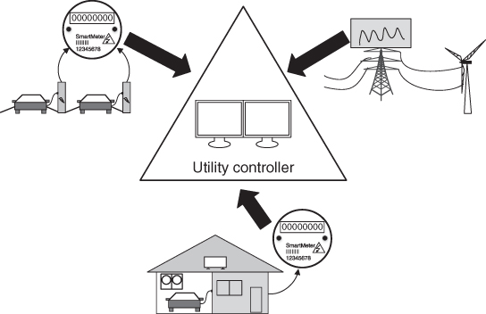
Figure 2.2 Examples of internal data collectors.
2.2.1 Internal Data Collectors
Internal data collectors are sensors and smart meters deployed in the smart grid. Specifically, smart meters are deployed at the customer's site by utility companies. Many types of sensors are deployed by utility companies to monitor transmission lines, substations, etc. In the smart grid, customers are motivated to actively participate in DR. Therefore, some of the information is given to customers while also being uploaded to utility companies. For instance, customers are granted access to the electricity usage data of their own properties. In many cases, customers themselves have established local‐area networks (LANs) or wireless LANs (WLANs), based on Wi‐Fi, Bluetooth, etc., that connect smart devices, smart appliances, and corresponding smart meters in each household. Smart devices can be smart phones, tablets, laptops, etc. Without loss of generality, smart phones will be used to indicate smart devices. From smart phones, customers are able to monitor electricity consumption of their appliances and possibly control them. In practice, LANs/WLANs established by customers usually have access to the Internet. Consequently, remote monitoring and remote control can be applied by customers anywhere they have Internet access.
Apart from fixed household appliances, electric vehicles (EVs) and plug‐in hybrid electric vehicles (PHEVs) are mobile appliances that have more resilient electricity requirements. For example, an EV can be charged in a household, but it can also be charged in a public charging station or a capable parking lot. Furthermore, some companies and researchers are pushing to standardize batteries for EVs. In that case, customers can go to a battery exchange station and replace depleted battery with a fully charged one. The electricity consumption of EVs at charging ports will be captured by corresponding smart meters or specific types of sensors. Other useful information, such as the location and possible routes of EVs, may be gathered by some external agents with the customers' permission. Such data will be considered as external data by the ICT framework.
Sensors deployed in the smart grid transmission line monitoring systems are internal data collectors as well. A typical sensor is a phasor measurement unit (PMU) that is used in wide‐area measurement systems (WAMS) to measure the electric waves on an electricity grid using a common time source for synchronization. Phasor data concentrators (PDC) are deployed to collect PMU data for the central control facility, and control and monitor the PMUs. For 60 Hz systems, PMUs must deliver between 10 and 30 synchronous reports per second, depending on the application [50].
2.2.2 Control Centers
Control centers are deployed and operated by utility companies. Specifically, there are three types of control centers in the proposed framework: local control centers, a cloud control center, and an authentication server (AS) with a private‐key generator (PKG). For simplicity, AS or PKG will be used interchangeably to indicate the group hereafter. It is also reasonable to assume that the PKG is a trusted third party. In terms of responsibility, control centers as a whole unit make the energy forecast to power generators, and the pricing forecast to customers. In DR, a control center is also responsible for direct load control (DLC) of both power consumption by customers and electricity generation by power generators. DLC usually applies to power companies themselves. For instance, they cycle air conditioners and water heaters on and off during periods of peak demand to smooth the power generation load.
The smart grid has a massive scale in almost every way: number of users, area of coverage, complexity of its infrastructure, etc. Therefore, local control centers need to be distributed across the power grid for better scalability and reliability in the proposed ICT framework. For instance, a local control center can be deployed close to or inside a power distribution substation. While each substation covers a relatively small area, a local control center is responsible for the customers within that particular area. Substations are currently connected by a high‐speed private backhaul network deployed by the utility company. With extra gateways to the backhaul network, local control centers are interconnected through the utilities' backbone networks. Although local control centers and private networks are controlled by utility companies, it is better to isolate data storage so that local control centers do not share collected data during normal operations. Some necessary conditions for a local control center to share or pass data to other local control centers include routine maintenance or temporary system downtime due to cyberattacks or natural disasters. The main functions of local control centers include:
- internal data (i.e. metering data and sensor data) collection;
- preprocessing sensitive data to protect the privacy of customers;
- real‐time direct control of the power grid;
- finalizing energy forecasts for power generators;
- generating price forecasts for customers.
Unlike local control centers, the cloud control center is a comprehensive unit composed of complicated and distributed hardware as well as software. Different types of services, such as infrastructure as a service, platform as a service, and software as a service, can be provided. Nonetheless, such complexity needs to be transparent to users (i.e. the utility company). Therefore, the cloud control center can be viewed as a powerful single unit in the framework. As shown in Figure 2.3, the cloud service provider serves the central power grid, detachable microgrids, customers' smart devices, and many other types of customers that are not part of the smart grid. Deploying and maintaining a large cloud computing center could be too expensive for utility companies. Thus it is reasonable to rent a cloud control center from a public cloud service provider at the cost of losing control of the data connection links, because the cloud control center is connected internally by high‐speed networks that are not controlled by the utility company. The main functions of the cloud control center in the ICT framework include:
- store data uploaded from local control center for a certain period;
- fetch data from external sources;
- perform big data analytics on collected data and make raw energy forecasts for each area and the entire grid.
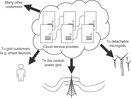
Figure 2.3 Cloud computing service and the power grid.
The raw energy forecast is sent back to local control centers for finalizing. Utilities may not fully trust the public cloud services and thus retain key features for finalizing energy forecast.
2.2.3 Power Generators
Power generators consist of central conventional energy sources and detachable renewable energy sources. If an energy forecast is provided for a sufficient time period to the grid operators, the transition between peak and off‐peak electricity generation is smoother and thus can be more efficient. This is straightforward for conventional power generators that use fossil fuel, since a forecast helps to control fuel consumption precisely. However, it may not be possible to control electricity generation from renewable energy sources even with energy forecasts. To tackle this issue, different types of power generators cooperate together within the ICT framework, as shown in Figure 2.4.
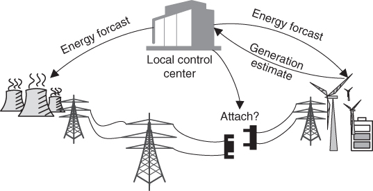
Figure 2.4 Example of power generators in the ICT framework.
Although renewable energy sources can hardly adjust their electricity generation according to an energy forecast, it is possible to have an estimate of their capacity based on environmental conditions and their energy storage units. The estimate is sent to a local control center to finalize an energy forecast that is mainly for central power stations. A specialized energy forecast is also sent to the renewable power stations mainly to determine if the power sources need to be attached to the main grid. Like weather forecasts, the energy forecast shall be updated with different levels of granularity based on the latest collected data and the results from data analysis.
2.2.4 External Data Sources
Due to many uncertainties, such as the generation capacity of renewable energy sources and consumer power usage patterns, internal data from the grid alone is not enough to make accurate energy and pricing forecasts. In order to improve research and development of smart grid features, different types of data from external sources are included in the ICT framework. For example, weather forecasts can provide better estimates of amount of electricity generated by renewable energy sources. Locations and routes of EVs can be used to estimate their energy consumption as well as their schedule. Useful information can also be extracted from many other external sources. The smart grid will certainly operate more efficiently with all this external data.
2.3 Communication Networks and Technologies
2.3.1 Private and Public Networks
Communications in the smart grid are achieved through private and public networks. Private networks are deployed and maintained by utilities. Public networks are provided by third‐party service providers, such as cellular connections and the Internet. In the current power grid, almost the entire network is private, because that allows it to be managed with better security. In the smart grid, a large portion of the communication infrastructures still operates on private networks. For example, metering data is uploaded through the advanced metering infrastructure which mainly utilizes private networks. The WAMS transmits monitoring data (e.g. PMU data) through private networks. Monitoring networks for power transmission lines are also private networks [51] if a real‐time connection is required. There are three important reasons for deploying private networks: security, reliability, and cost.
- Security is one important reason for deploying private networks. For instance, metering data is gathered from customers, thus it contains much private and sensitive information about customers. The lifestyle of a customer may be revealed if metering data is leaked.
- Reliability is another important issue. For instance, real‐time monitoring in the smart grid requires low latency (e.g. 10 to 100 ms for PMUs in WAMS). Public cellular networks or Internet service providers can hardly meet the latency requirement, due to their complicated protocols and mechanisms. The private networks in the smart grid are designed specifically to fulfill the latency requirement.
- Cost is also a reason for private networks. Subscription fees for public network service providers can be overwhelmingly high in the long run. Moreover, the power grid may cover a larger area than a public network service does. For instance, power transmission line monitoring networks may cover remote areas that have no public network access. The private networks are built on different types of communication technologies, including various types of wireless networks (e.g. Wi‐Fi, Zigbee, WiMAX, etc.) and high‐speed wired networks (e.g. fiber optics and Ethernet) [52]. Specific technologies are chosen to balance optimal network performance with hardware and maintenance costs.
2.3.2 Communication Technologies
Without loss of generality, we will discuss communication technologies applied to AMI and WAMS for illustration. AMI and WAMS constitute most of the communication infrastructure in the smart grid. Other communication networks can be explored based on the ones applied to AMI and WAMS with slight modifications.
AMI is one of the most important infrastructures in the smart grid. The communication networks of AMI in the smart grid generally consist of home‐area networks (HANs), neighborhood‐area networks (NANs), and a wide‐area network (WAN). An overview of AMI is shown in Figure 2.5. A HAN is established within a household, connecting a smart meter and smart appliances with sensors and actuators. Smart meters upload metering data to data aggregate units (DAPs) that are deployed in a neighborhood. A NAN is formed by DAPs and smart meters in a neighborhood. Metering data is finally gathered by the metering data management system (MDMS) through the high‐speed WAN. MDMS will provide storage, management, and processing of meter data for proper usage by other power system applications and services.

Figure 2.5 High‐level illustration of the advanced metering infrastructure.
Wireless technologies have been widely used in the last‐mile communication systems (i.e. HANs and NANs) in the smart grid [25, 26, 53–55] because of their flexibility in deployment and environmental adaptiveness, especially in extreme situations. A HAN is similar to a local‐area network. Numerous works have been proposed to study HAN as a network with a small coverage area and a low rate of data transmission, including a single smart meter as the collector and several smart appliances. Both wireless and wire‐line technologies can be applied to HANs. As shown in Table 2.1, wireless transmission technologies include Wi‐Fi, Bluetooth, ZigBee and Z‐Wave [56].
- Wi‐Fi is based on open international standards IEEE 802.11 a/b/g/n/ac. Wi‐Fi is designed for providing wireless connections for accessing the Internet and is a direct replacement for the traditional Ethernet network. Wi‐Fi is easy to deploy and supports mesh topology.
- Bluetooth is based on the open international standard IEEE 802.15.1. It is designed for consumer electronics to provide short‐range wireless communications for connecting a wide range of devices easily and quickly. Bluetooth is the most popular protocol for transferring data, provides a wireless alternative to RS‐232 data cables, and supports ring topology.
- ZigBee belongs to the same international standard family as Bluetooth, that is IEEE 802.15.4. ZigBee is designed specifically for industrial and home automation for connecting sensors, monitors, and control devices. ZigBee has low power requirements and implementation costs. It also supports mesh topology.
- Z‐Wave is a proprietary wireless standard designed for home control automation, specifically for remote control applications in residences. It was originally developed by Zensys A/S and is being marketed by Z‐Wave Alliance. Z‐Wave wireless protocol provides reliable and low‐latency communication of small data packets within HANs. Z‐Wave has low power, low latency, and low cost. It has less interference due to its use of sub‐GHz frequency. It also has higher propagation range (i.e. is 2.5 times that of a 2.4 GHz signal) and supports mesh topology.
Table 2.1 Enabling wireless technologies in HANs.
| Key Criteria | Wi‐Fi | Bluetooth | ZigBee | Z‐Wave |
| Frequency band | 2.4 GHz | 2.4 GHz | 868/915 MHz | 900 MHz |
| 5 GHz | 2.4 GHz | |||
| Speed | 54 Mbps (b/g) | 2.1 Mbps (V2.0) | 250 Kbps | 9.6 Kbps |
| 150 Mbps (n) | 25 Mbps (V3.0/4.0) | |||
| 433 Mbps (ac) | 50 Mbps (V5.0) | |||
| Range | 70 m (in) | 10 m | 70 m (in) | 30 m (in) |
| 250 m (out) | 450 m (out) | 100 m (out) | ||
| Power | High | Lower | Lowest | Lowest |
| Maximum nodes | 2007 | 8 | over 64,000 | 232 |
Short‐range wired communication technologies are also candidates for HANs. As shown in Table 2.2, some candidates are X10, HomePlug GP, BACnet and KNX.
- X10 is an open standard that is designed for providing simple automation functionality, such as on and off.
- HomePlug GP is based on international standard IEEE 1901. It is designed for consumer electronics to provide short‐range wireless communication to connect a wide range of devices easily and quickly.
- BACnet is based on the open standard ISO 16484‐5 and ANSI/ASHRAE 135‐2008. It is a data communication protocol that attempts to unifies all the proprietary communication protocols into single communication language.
- KNX is based on standards IOS/IEC 14543‐3, GB/Z 20965, ANSI/ASHRAE 135, CENELEC EN 50090 and CEN EN 13321‐1. It is a global standard protocol designed basically for home automation and control.
Table 2.2 Enabling wired technologies in HANs.
| Key Criteria | X10 | HomePlug GP | BACnet | KNX |
| Wireless | Yes | Yes | No | Yes |
| Support | 310 MHz | ZigBee | KNX RF | |
| 433 MHz | 868.3 MHz | |||
| Speed | 20 bps | 4–10 Mbps | Depends on | 9.6 kbps (wired) |
| LAN used | 16.4 kbps (wireless) | |||
| Maximum | 256 | 253 (Theoretically) | No limit | 57,600 (wired) |
| nodes | 10 (Practically) |
A NAN is a bridge connecting HANs and the WAN, as shown in Figure 2.6. It consists of many DAPs, each collects data from several smart meters and transmits the data to a concentrator through NAN gateways in their uplink transmissions. The DAPs also broadcast the control information from the MDMS to their surrounding smart meters. Specific control messages to a certain smart meter are also transmitted through DAPs. A DAP communicates with its surrounding smart meters with the same technologies that form a HAN. Internal communications in a NAN (i.e. communications between DAPs) are proposed to be accomplished by Wi‐Fi (especially by following IEEE 802.11s) because a NAN is a wireless mesh network with high data transmission rates. Some of the DAPs are also equipped with cellular technologies such as WiMAX or LTE for reliable longer‐distance transmission to the concentrator (i.e. a gateway to backhaul networks). Besides wireless technologies, wired technologies are also applied to NANs. A widely used wired technology is PLC, which may operate in ultra‐narrow band, narrow band, and broadband. Frequency band information is given in Table 2.3.
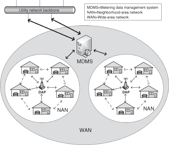
Figure 2.6 High‐level illustration of NANs.
Table 2.3 PLC operating frequency bands.
| Type | Frequency bands |
| Ultra narrow band PLC | |
| Narrow band PLC | |
| Broadband PLC |
The WANs are part of the backhaul networks in the smart grid. PLC, Internet protocol (IP)‐based networks, and some wireless technologies can be applied to WANs. The pros and cons of each technology are given below:
- Pros of PLC in WANs
- Provides a low‐cost solution to overlay the communication network over already available power lines.
- Complete control over the communication path with extensive coverage that is solely controlled by the utility industry.
- Provides a direct route between controllers and other subsystem to ensure low latency.
- Mature technology with many variants available commercially.
- Cons of PLC in WANs
- Power lines are connected to various kinds of equipment, such as motors or power supplies, that can act as noise sources that eventually degrade the performance of the PLC.
- The load impedance fluctuation and electromagnetic interference cause signal attenuation and distortion, which can result in the failure of the communication link.
- Lack of standards and government regulation due to industry fragmentation result in high interference from other PLC technologies deployed at close range.
- Costs of PLC modems are still high.
- There is a coexistence issue with many commercial technologies.
- Pros of IP‐based networks in WANs
- They have rich convergence capabilities that can help to connect the overall systems and subsystems in smart grid
- They can provide quality of service and reliable connection using technologies such as DiffServ and MPLS.
- Security can be enhanced using known technologies (i.e. IPSec).
- Cons of IP‐based networks in WANs:
- In the case of a master/slave configuration, transmitting IP packets from the slave is not possible, which might increase the data latency for those applications that require fast response, as smart grid does.
- Unless a private IP‐based network (e.g. Internet VPN) is used, security remains a crucial issue.
- Pros of wireless networks in WANs
- They provide a huge coverage area, potentially at a low cost
- Cellular data transmission has lower costs and much higher data rates.
- Some wireless technologies (e.g. WiMAX) can support mesh networks for higher reliability.
- Cons of wireless networks in WANs
- Utilities have to depend on these technologies without any control over them.
- A connection to the network is required before data can be transmitted, which may be a problem in case of outages and emergencies.
- Longer latency degrades real‐time services.
Besides private networks, smart grid communications also utilize the Internet. PMUs and PDCs in WAMS can use ubiquitous cellular networks, such as GPRS, UMTS, and LTE, for data transfers. Smart appliances may connect to an established Wi‐Fi network with Internet access. Public cloud computing service can be involved in the smart grid, and use of the Internet is inevitable for communications from and to cloud computing services. However, public cellular networks or ISPs can hardly meet the latency requirements due to complicated protocols and mechanisms, which limits their use in real‐time protective systems.
2.4 Data Communication Requirements
Communications in the smart grid have various requirements. Some of the major requirements are latency and bandwidth, interoperability, scalability, and security. Those requirements must be considered together in the design and deployment of smart grid communications along with other issues, such as reliability, availability, and cost.
2.4.1 Latency and Bandwidth
Several types of data are transmitted in the smart grid with different latency requirements [57]. One characteristics of communication is that many interactions must take place in real time, with hard time bounds. The real‐time operational data communications in the smart grid include online sensor/meter reading and power system control signals. Power system control signals mainly include supervisory control of the power process on secondary or higher levels. Several applications and their corresponding latency requirements in the smart grid are listed in Table 2.4.
Table 2.4 Data communication latency requirements.
| Application | Latency Requirement |
| Demand response | 2 s–5 min |
| Remote connect/disconnect | 2–5 s |
| AMI, real‐time pricing | 2 s |
| Metering data management | |
| Outage management | 300 ms–2 s |
| In‐home displays | |
| Emergency response | 10–100 ms |
| Synchro‐phasor | 10–100 ms |
| DA protection event notification | 3–10 ms |
As more and more interconnected intelligent elements are added to the smart grid, the communication infrastructure should be able to transport more and more data simultaneously without severe impacts on latency. Therefore, the network bandwidth must increase faster than the demand of these interconnected intelligent elements in the network. For example, a distribution substation connected to 10,000 feeders with each feeder attached to 10 customers could require a bandwidth that is over 100 Mbps if a message is generated every second. With more frequent message transmissions, bandwidth should be expected to increase in smart grid communications.
2.4.2 Interoperability
Interoperability is the ability of two or more networks, systems, devices, applications, or components to communicate and operate together effectively and securely, without significant user intervention. To achieve interoperability, smart grid communications require agreement on a physical interface and communication protocols. In addition, exchanging meaningful and actionable information requires common definitions of terms and agreed‐upon responses. Moreover, consistent performance requires standards for the reliability, integrity, and security of communications.
2.4.3 Scalability
Scalability is another critical issue in smart grid communications. The smart grid communications system involves huge numbers of customers and countless sensors, and it also covers vast geographical areas. For example, the MDMS is considered a centralized control center in AMI. However, in practice, it is better to deploy it in a distributed way to achieve efficient communications that can meet the latency requirements. The amount of data to be gathered and processed in the AMI is massive, and customers are spread across cities and the countryside.
2.4.4 Security
Finally, network security is inevitable in smart grid communications. Various pieces of data in smart grid communications may contain much private information about customers, as well as control messages that operate the grid. Leakage of metering data will jeopardize the privacy of customers. Forging or manipulating control data may hamper optimal demand response. In addition, alteration of sensing data from WAMS may lead to severe system failures or blackouts.
2.5 Summary
In this chapter, we presented an information and communication technologies framework for the smart grid. The ICT framework is intended to show the pieces of the entire communication network and their integration with physical components in the smart grid so that utilities can improve interoperability of different domains. In addition, requirements for possible technologies of communication networks to support the smart grid were also discussed in this chapter. It is recommended that readers get a better understanding of the specific communication technologies mentioned in this chapter, such as Wi‐Fi, Bluetooth, ZigBee, WiMAX, PLC, etc.