
10
The I2C Bus
Parts You'll Need for This Chapter
- Arduino Uno or Adafruit METRO 328
- USB cable (Type A to B for Uno, Type A to Micro-B for METRO)
- Half-size or full-size breadboard
- Assorted jumper wires
- 220Ω resistors (×8)
- 4.7kΩ resistors (×2)
- 5 mm red LED
- 5 mm green LEDs (×4)
- 5 mm yellow LEDs (×3)
- SN74HC595N shift register
- TC74A0-5.0VAT I2C temperature sensor
- CODE AND DIGITAL CONTENT FOR THIS CHAPTER
- Code downloads, videos, and other digital content for this chapter can be found at:
exploringarduino.com/content2/ch10- Code for this chapter can also be obtained from the Downloads tab on this book's Wiley web page:
wiley.com/go/exploringarduino2e
You've already learned how to connect both analog and digital inputs and outputs, but what about more complicated devices? The Arduino (or any microcontroller, for that matter) can expand its capabilities by interfacing with a variety of external components. Many integrated circuits (ICs) can implement standardized digital communication protocols to facilitate communication between your microcontroller and a wide array of possible modules. This chapter explores the I2C bus (pronounced “eye squared see” or “eye two see”).
The I2C bus enables robust, high-speed, two-way communication between devices while using a minimal number of I/O pins to facilitate communication. Usual maximum speeds range from 100 kilobits per second (Kbps) up to a few megabits per second (Mbps), depending on the components and system design. An I2C bus is controlled by a master device (usually a microcontroller or microprocessor), and contains one or more slave devices that receive information from the master. In this chapter, you will learn about the I2C protocol, and you will implement it to communicate with a digital I2C temperature sensor capable of returning measurements as degree values rather than arbitrary analog values. You will build upon knowledge obtained from previous chapters by combining what you learn in this chapter to expand on earlier projects.
History of the I2C Bus
Understanding how a communication protocol evolved over time makes it a lot easier to understand why it works the way it does. The I2C protocol was developed by Philips Semiconductors in the early 1980s to allow for relatively low-speed communication between various integrated circuits. The protocol was standardized by the 1990s, and other companies quickly began to adopt the protocol, releasing their own compatible chips. Generically, it is known as the “two-wire” protocol because two lines are used for communication: a clock and data line. Although not all two-wire protocol devices have paid the license fee to be called I2C devices, they are all commonly referred to as I2C. This is similar to how Kleenex® is often used to refer to all tissues, even those that aren't manufactured by Kimberly-Clark. If you find a device that says it uses the “two-wire” communication protocol, you can be fairly certain that it will work in the ways described in this chapter.
You might also find devices that utilize the SMBus (System Management Bus). Derived from the I2C standard by Intel and Duracell, the SMBus standard is very similar to I2C, but implements some slightly different electrical limits, defines a protocol for error checking, and explicitly supports an optional interrupt signal line to enable slaves to notify the master of certain events. It is usually possible to successfully mix SMBus devices and I2C devices on the same bus if you are careful to follow the requirements in all of the devices’ datasheets.
I2C Hardware Design
Figure 10-1 shows a common reference setup for an I2C communication system. Unlike digital communication systems that you've seen earlier in this book, I2C is unique in that multiple devices all share the same communication lines: a clock signal (SCL) and a bidirectional data line used for sending information back and forth between the master and the slaves (SDA). Notice, as well, that the I2C bus requires pull-up resistors on both data lines.

Figure 10-1: I2C reference hardware configuration
Created with EAGLE
Communication Scheme and ID Numbers
The I2C bus allows multiple slave devices to share communication lines with a single master device. In this chapter, the Arduino acts as the master device. The bus master is responsible for initiating all communications. Slave devices cannot initiate communications; they can only respond to requests that are sent by the master device. Because multiple slave devices share the same communication lines, it's very important that only the master device be able to initiate communication. Otherwise, multiple devices may try to talk at the same time and the data will be garbled.
All commands and requests sent from the master are received by all devices on the bus. Each I2C slave device has a unique 7-bit address, or ID number. When communication is initiated by the master device, a device ID is transmitted. I2C slave devices react to data on the bus only when it is directed at their ID number. Because all the devices are receiving all the messages, each device on the I2C bus must have a unique address. Some I2C devices have selectable addresses, whereas others come from the manufacturer with a fixed address. If you want to have multiple numbers of the same device on one bus, you need to identify components that are available with different IDs.
Temperature sensors, for example, are commonly available with various preprogrammed I2C addresses because it is common to want more than one temperature sensor on a single I2C bus. In this chapter, you will use the TC74 temperature sensor. A peek at the TC74 datasheet reveals that it is available with a variety of different addresses. Figure 10-2 shows an excerpt of the datasheet. In this chapter, you will use TC74A0-5.0VAT, which is the 5V, T0-220 version of the IC with an address of 1001000.

Figure 10-2: TC74 address options
Credit: © Microchip Technology Incorporated. Used with permission.
You can purchase this particular IC with eight different ID numbers; hence, you could put up to eight of them on one I2C bus and read each of them independently. When you're writing programs to interface with this temperature sensor later in this chapter, be sure to note the ID of the device you ordered so that you send the right commands!
Other I2C chips, such as the AD7414 and AD7415 (another I2C digital temperature sensor manufactured by Analog Devices), have “address select” (AS) pins that allow you to configure the I2C address of the device. Take a look at the excerpt from the AD7414 datasheet in Figure 10-3.

Figure 10-3: AD7414 addressing
Credit: Copyright © 2019, Analog Devices, Inc. All Rights Reserved.
As shown in Figure 10-3, the AD7414 is available in four versions: two with an AS pin and two without. The versions with AS pins can each have three possible ID numbers, depending on whether the AS pin is left disconnected, tied to VCC, or tied to GND.
Hardware Requirements and Pull-Up Resistors
You may have noticed in Figure 10-1 that the standard I2C bus configuration requires pull-up resistors on both the clock and data lines. The value for these resistors depends on the slave devices and how many of them are attached. In this chapter, you will use 4.7kΩ resistors for both pull-ups; this is a fairly standard value that is specified on many datasheets.
Communicating with an I2C Temperature Probe
The steps for communicating with different I2C devices vary, based on the requirements of the specific device. Thankfully, you can use the Arduino I2C library to abstract away most of the difficult timing work. In this section, you will talk to the I2C temperature sensor described earlier in the chapter. You will learn how to interpret the datasheet information as you progress so that you can apply these concepts to other I2C devices with relative ease.
The basic steps for controlling any ICC device are as follows:
- The master sends a start bit.
- The master sends a 7-bit slave address of the device it wants to talk to.
- The master sends a read (1) or write (0) bit, depending on whether it wants to write data into an I2C device's registers or it wants to read from one of the I2C device's registers.
- The slave responds with an “acknowledge” or ACK bit (a logic low).
- In write mode, the master sends 1 byte of information at a time, and the slave responds with ACKs. In read mode, the master receives 1 byte of information at a time and sends an ACK to the slave after each byte.
- When communication has been completed, the master sends a stop bit.
Setting Up the Hardware
To confirm that your first program works as expected, you can use the serial monitor to print out temperature readings from an I2C temperature sensor to your computer. Because this is a digital sensor, it prints the temperature in degrees. Unlike the temperature sensors that you used in previous chapters, you do not have to worry about converting an analog reading to an actual temperature. How convenient! Now, wire a temperature sensor to the Arduino as shown in Figure 10-4.

Figure 10-4: Temperature sensor
Created with Fritzing
Note that the SDA and SCL pins are wired to pins A4 and A5, respectively. Recall from earlier in the chapter that the SDA and SCL are the two pins used for communicating with I2C devices—they carry data and clock signals, respectively. You've already learned about multiplexed pins in previous chapters. On the Arduino Uno (and other ATmega 328-based Arduinos), pins A4 and A5 are multiplexed between the analog-to-digital converter (ADC) and the hardware I2C interface. When you initialize the Wire library in your code, those pins connect to the ATmega's internal I2C controller, enabling you to use the wire library to talk to I2C devices via those pins. When using the Wire library, you cannot use pins A4 and A5 as analog inputs because they are reserved for communication with I2C devices. On the latest revisions of the Arduino boards, there are also dedicated I2C pins above the AREF pin (they are electrically connected to the A4/A5 pins and are functionally identical). You can connect to those pins if you prefer.
Referencing the Datasheet
Next, you need to write the software that instructs the Arduino to request data from the I2C temperature sensor. The Arduino Wire library makes this fairly easy. To use it properly, you need to know how to read the datasheet to determine the communication scheme that this particular chip uses. Let's dissect the communication scheme presented in the datasheet, using what you already know about how I2C works. Consider the diagrams from the datasheet shown in Figure 10-5 and Figure 10-6.
You can both read from and write to this IC, as shown in the datasheet in Figure 10-5. The TC74 has two registers: one that contains the current temperature in Celsius and one that contains configuration information about the chip (including standby state and data-ready state). Table 4-1 of the datasheet shows this. You don't need to mess with the configuration information; you only want to read the temperature from the device. Tables 4-3 and 4-4 in Figure 10-6 show how the temperature information is stored within the 8-bit data register.

Figure 10-5: TC74 sensor communication scheme
Credit: © Microchip Technology Incorporated. Used with permission.

Figure 10-6: TC74 register information
Credit: © Microchip Technology Incorporated. Used with permission.
The “Read Byte Format” section of Figure 10-5 outlines the process of reading the temperature from the TC74:
- Send to the device's address in write mode and write a
0to indicate that you want to read from the data register. - Send to the device's address in read mode and request 8 bits (1 byte) of information from the device.
- Confirm that all 8 bits (1 byte) of temperature information were received.
Now that you understand the steps necessary to request information from this device, you should better understand how similar I2C devices would also work. When in doubt, search the web for code examples that show how to connect your Arduino to various I2C devices. Next, you will write the code that executes the three steps outlined earlier.
Writing the Software
Arduino's I2C communication library is called the Wire library. After you insert it at the top of your sketch, you can easily write to and read from I2C devices. As a first step for your I2C temperature sensor system, load up the code in Listing 10-1, which takes advantage of the functions built in to the Wire library. See whether you can match up various Wire commands in the code with the steps outlined in the previous section.
Consider how the commands in this program relate to the previously mentioned steps. Wire.beginTransmission() starts the communication with a slave device with the given ID. Next, the Wire.write() command sends a 0, indicating that you want to be reading from the temperature register. You then send a stop bit with the Wire.endTransmission() command to indicate that you have finished writing to the device. Next, the master reads from the slave I2C device. The Wire.requestFrom() command asks for a certain amount of data (1 byte) and then returns the number of bytes that were actually received. This is stored into a variable called returned_bytes. This value is then checked; if it is zero, then the I2C devices did not return any data. This generally implies a hardware problem, such as the sensor not being wired up properly. Thus, an error is printed to the serial monitor and the program enters an endless wait loop if this condition is triggered. Assuming that data was received back from the I2C device, the 8-bit value is read into an integer variable with a Wire.read() command.
The program in Listing 10-1 also handles converting the Celsius temperature to Fahrenheit, for those who are not metrically inclined. You can find the formula for this conversion with a simple web search. I've chosen to round the result to a whole number.
Now, run the preceding code on your Arduino and open up the serial monitor on your computer. You should see output similar to Figure 10-7. If you receive an error, then your sensor is not properly wired to your Arduino.
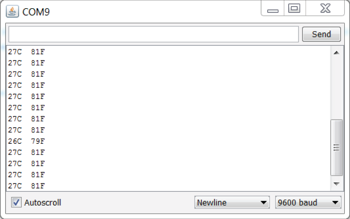
Figure 10-7: I2C temperature sensor serial output
Combining Shift Registers, Serial Communication, and I2C Communications
Now that you have a simple I2C communication scheme set up with serial printing, you can apply some of your knowledge from previous chapters to do something more interesting. You will use the shift register graph circuit from Chapter 9, “Shift Registers,” along with a Processing desktop sketch to visualize temperature in the real world and on your computer screen.
Building the Hardware for a Temperature Monitoring System
First things first: get the system wired up. You're essentially just combining the shift register circuit from the previous chapter with the I2C circuit from this chapter. Your setup should look like Figure 10-8.

Figure 10-8: I2C temperature sensor with a shift register bar graph
Created with Fritzing
Modifying the Embedded Program
You need to make two adjustments to the previous Arduino program to make serial communication with Processing easier, and to implement the shift register functionality. First, modify the temperature printing statements in the program you just wrote to look like this:
Serial.print(c);Serial.print("C,");Serial.print(f);Serial.print("F.");
Modify the Serial.println("I2C Error"); error condition to also print a similarly formatted message (two values separated by a comma, and ending with a period):
Serial.print("Err,Err.");Processing needs to parse the Celsius and Fahrenheit temperature data. By replacing the spaces and carriage returns with commas and periods, you can easily look for these delimiting characters and use them to parse the data.
Next, you need to add the shift register code from the previous chapter, and map the LED levels appropriately to the temperature range that you prefer. If you a need a refresher on the shift register code that you previously wrote, take another look at Listing 9-3; much of the code from that program will be reused here, with a few small tweaks. To begin, change the total number of light variables from nine to eight. With this change, you always leave one LED on as an indication that the system is working. (The 0 value is eliminated from the array.) You need to accommodate for that change in the variable value mapping, and you need to map a range of temperatures to LED states. Check out the complete code sample in Listing 10-2 to see how that is done. I chose to make my range from 24°C to 31°C (75°F to 88°F), but you can choose any range.
After loading this code on to your Arduino, you can see the LEDs changing color with the temperature. Try squeezing the temperature sensor with your fingertips to make the temperature go up; you should see a response in the LEDs. Next, you will write a Processing sketch that displays the temperature value on the computer in an easy-to-read format.
Writing the Processing Sketch
At this point, your Arduino is already transmitting easy-to-parse data to your computer. All you need to do is write a Processing program that can interpret it and display it in an attractive way.
Because you'll be updating text in real time, you need to first learn how to load fonts into Processing. Open Processing to create a new, blank sketch. Save the sketch before continuing. Then, navigate to Tools ➢ Create Font. You see a screen that looks like Figure 10-9.

Figure 10-9: Processing font creator
Pick your favorite font and specify a size. (I recommend a size of around 200 for this exercise.) When you're done, click OK. The font is automatically generated and added to the data subfolder of your Processing sketch folder. The Processing sketch needs to accomplish a few things:
- Generate a graphical window on your computer showing the temperature in both Celsius and Fahrenheit.
- Read the incoming data from the serial port, parse it, and save the values to local variables that can be displayed on the computer.
- Continually update the display with the new values that are received over the serial link.
Copy the code from Listing 10-3 into your Processing sketch and adjust the serial port name to the right value for your computer and the name of the font you created. Then, ensure your Arduino is connected and click the Run icon to watch the magic! Don't forget to ensure that the serial monitor in the Arduino IDE is closed, first—only one program can access the serial port at a time.
As in previous Processing examples that you've run, the sketch starts by importing the serial library and setting up the serial port. In setup(), you are defining the size of the display window, loading the font you just created, and setting up the serial port to buffer until it receives a period. draw() fills the background in black and prints out the Celsius and Fahrenheit values in two colors. With the fill() command, you are telling Processing to make the next element it adds to the screen that color (in RGB values). serialEvent() is called whenever the bufferUntil() event is triggered. It reads the buffer into a string, and then breaks it up based on the location of the comma. The two temperature values are stored in variables that are printed out in the application window.
When you execute the program, the output should look similar to Figure 10-10.
When you squeeze the sensor, the Processing display should update, and the lights on your board should illuminate. If you see “Err Err” on the processing display, that means that your temperature sensor is not returning a value when queried over I2C—check the wiring.

Figure 10-10: Processing temperature display
Summary
In this chapter, you learned the following:
- I2C uses two data lines to enable digital communication between the Arduino and multiple slave devices (as long as they have different addresses).
- The Arduino Wire library can be used to facilitate communication with I2C devices connected to the Arduino's SCL and SDA pins.
- I2C communication can be employed alongside shift registers and serial communication to create more complex systems.
- You can create fonts in Processing to generate dynamically updating onscreen displays.
- Processing can be used to display parsed serial data obtained from I2C devices connected to the Arduino.