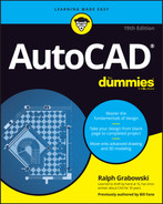
Chapter 19
Call the Parametrics!
IN THIS CHAPTER
![]() Introducing parametric drawing
Introducing parametric drawing
![]() Understanding constraints
Understanding constraints
![]() Applying geometric and dimensional constraints
Applying geometric and dimensional constraints
![]() Editing parametric drawings
Editing parametric drawings
A decade ago, Autodesk added parametric tools to AutoCAD, and I can’t think of a more significant new feature in recent years. In fact, if you work primarily in 2D, and especially if you’re in the manufacturing business, parametrics in AutoCAD (and, to a very limited degree, in AutoCAD LT) might just be the most significant new feature since the beginning of orthographic engineering drawings, generally attributed to the Roman architect Marcus Vitruvius in the 1st century BC. Contrary to popular opinion, I am not so old that I knew him personally.
Parametric tools allow you to create relationships between geometry and control the size of geometry in drawings. These relationships constrain changes to designs, so parametric tools are also known as constraints. The power of parametrics comes in their capability to quickly generate variations of a design. A single design of, say, a bicycle can be output with bigger (or smaller) wheels and longer (or shorter) handle bars, once all parametric parameters are set up correctly.
If you know what I’m talking about, you’re probably going to be pretty interested in finding out more about what you can do with parametrics in AutoCAD. If, on the other hand, you think parametrics are the folks who show up when you dial 911, the following paragraphs should straighten you out.
Imagine this scenario: Your boss has been in a meeting all morning with an important client. At two minutes before noon, they emerge. Your boss hands you a marked-up printout and commands you rather imperiously: “We need these twelve dimensions changed and the drawing updated by the time we return from lunch.” The drawing involves multiple views, several cross sections, and a couple of details at different scales.
By the time the pair put on their coats, you’ve met them at the door and handed them a printout of the revised drawing. The client invites you to join them for lunch.
This chapter shows you how to make this scene happen in real life.
Maintaining Design Intent
Parametric (rule-based) drawing is by far the best way to enforce design intent in 2D drafting. Design intent in AutoCAD (and in any other engineering software) means that when drawings are edited to make “this part” wider and “that hole” larger, all the attached or related objects behave in a predictable way that honors the designer’s intent in creating the drawing.
Before AutoCAD 2010, there was simply no practical way to maintain the design concepts behind an AutoCAD drawing. You could use AutoCAD drawing and editing commands to draw accurate, precise plans, sections, and details, but they were, to AutoCAD, simply a bunch of lines and circles.
Suppose that an engineer has taken a second look at a baseplate (see Chapter 3) and determined that its 1½″ bolts should be changed to 1¾″. To revise the drawing in AutoCAD’s traditional way, you would draw a new, larger circle for the bolt and erase the old one — or maybe use the OFFSET command. But now the nut is too small, and so is the hole through the plate. Maybe you can’t see it, but you know — and I know — that the problems are there. And you have four of these changes to make. That’s a lot of editing to fix a simple drawing. Even so, the good news is that CAD editing is still a lot easier than using paper and pencil and eraser.
By applying parametric constraints, you can add intelligence to those lines and circles in AutoCAD. Rather than try to explain what the intelligence means, I show you.
AutoCAD does not support 3D constraints, such as those found in Inventor. The constraints in AutoCAD are 2D only.
Unfortunately, the following exercise doesn’t work in AutoCAD LT, although it can display and edit constraints added in full AutoCAD.
Follow these steps to constrain a line to a circle with parametrics:
- Start a new drawing.
Draw a circle and a line anywhere in the drawing.
Specifying exact sizes and alignments isn’t critical. You’ll see why in a moment, and I explain even more a little later in this chapter.
Apply a tangent constraint between the circle and the line.
 Parametric functions are found on the Ribbon’s Parametric tab. Nothing in AutoCAD should surprise you by now. Click the Tangent button, and then select the circle and the line. The sequence doesn’t matter. Observe how the second object you selected jumps to be tangent to the first one you selected. Note the little gray icon (called a constraint bar) that indicates the type of constraint.
Grip-edit the line and the circle.
You can move the circle or line, change the diameter of the circle, or move either end of the line — but no matter what you do, the other object obediently — stubbornly — remains tangent. I cover grip editing in Chapter 11. Note that tangent doesn’t necessarily mean that the objects need to touch.
Apply a diameter constraint dimension to the circle.
 Don’t use the normal DimDIameter or DIM command, described in Chapter 14. Instead, click the Diameter button in the upper-right corner of the Dimensional panel of the Parametric tab on the Ribbon. When you select the circle as prompted, AutoCAD places a gray-colored dimension that reads something like this:
 dia1=5.3716. The gray look of the dimension tells you that it's a constraint; the dia1 text tells you that it's the first (1) diameter (dia) constraint placed in the drawing.Change the diameter of the circle.
It has the same background color as the mText edit box (see Chapter 13); in fact, that’s exactly what it’s inviting you to do. Enter a different value, say, 7.5. The circle resizes to match the diameter value you entered, and the line adjusts to remain tangent. Magic!
It’s the opposite of associative dimensions (see Chapter 14). Here, the value of constraints determines the size and positions of objects; with associative dimensions, objects determine the values and positions of regular dimensions.
Apply an aligned constraint dimension to the line.
 Again, be sure to click the Aligned button from the Dimension panel on the Parametric tab, and not use the DIM command. Select each end of the line in turn or press Enter and then select the line. This time, when AutoCAD places the dimension, enter =dia1*2 including the equal sign and omitting spaces. The line automatically resizes to become twice as long as the diameter of the circle.
Double-click the diameter dimensional constraint and type a new value, such as 5, and press Enter.
Surprise! The size of the circle and the length of the line change, so that the line is still twice as long as the new diameter of the circle. That is one smart drawing. Imagine a similar effect on your productivity in creating and editing drawings.
You can still grip-edit the position of the line and circle, but you can no longer change the diameter of the circle or the length of the line using grips editing, nor can you stretch the line length any more. Constraints are in control!
Defining terms
The word parameter is derived from these two Greek roots:
- para: To work with, to assist, to work alongside. Think of paramedic ambulance attendants. You may have thought “ambulance” when I mentioned parametrics earlier in this chapter.
- metros: To measure (hence meter and metric). For the purposes of making drawings in AutoCAD, a parameter is a rule that works alongside AutoCAD objects. You can think of parametric drawing as rule-based drawing.
AutoCAD’s parametric rules (officially called constraints) fall into two categories:
- Geometric: Constrains the sizes of object and the relationships between them; different object types have varying constraints you can apply to them. In the example in the preceding step list, I show you how to apply a Tangent constraint between the line and the circle — as you move or change one, the other one follows along.
- Dimensional: Constrains the size of objects and the distances between objects. In the earlier example, you see how to apply a dimensional constraint to the circle. Changing the dimension value changes the circle size. Better yet, you can establish a relationship between the circle and the line so that changing the circle diameter also changes the length of the line.
Both AutoCAD and AutoCAD LT support constraints, but (as is usually the case) the feature is limited in LT. If you use the full version of AutoCAD, you can create and modify geometric and dimensional constraints, as I describe in the steps in this chapter. If you’re using LT, you can’t create constraints, but you can work with existing constraints in drawings that were created in AutoCAD. Figure 19-1 shows the difference between the AutoCAD and AutoCAD LT Parametric tabs.
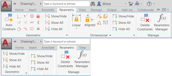
FIGURE 19-1: Parametric tabs in AutoCAD (top) and AutoCAD LT (bottom).
 If you’re using AutoCAD LT, or if you just want to check out some ready-made parametric possibilities, you can download the sample drawing datasets from either
 www.autodesk.com/autocad-samples or www.autodesk.com/autocadlt-samples. The parametric samples are architectural_example-imperial.dwg, civil_example-imperial.dwg, and mechanical_example-imperial.dwg.
Forget about drawing with precision!
“Are you serious, dude? Throughout this book, you have continually nagged me about the need for drawing with precision, and now you want me to forget about it?”
I’m sure that you’re familiar with, or at least have come across, computer acronyms and abbreviations, such as RAM, DVD, USB, and, of course, CAD. Okay, here’s a new one that I coined for a magazine article a few years back: NAD, or Napkin-Aided Design. It has been my observation that the vast majority of design projects start life as sketches on coffee-shop napkins.
A major strength of CAD is that drawings can (and should) be so precise that you can confidently make use of the information in them, such as volumes, areas, and lengths. On the other hand, a major weakness of CAD is that you’re forced to be precise, even early in the design process, when design ideas are not yet fixed and circumstances often change. Yes, commands such as Move and Stretch make editing relatively easy to use, but relatively in a relative way, and easy to use is easy to say.
With parametrics, you can start out with a NAD sketch that shows the general idea of your design. You don’t have to decides on the exact size and placement of objects from the get-go. Remember my parametric motto: Close enough is good enough. By the way, the motto also applies to horseshoes, hand grenades, and dancing. Then apply geometric and dimensional constraints and formulas to those vaguely placed objects to progressively fine-tune their values until you arrive at your final design.
You can apply dimensional or geometric constraints to new geometry as you create it, or you can assign constraints afterwards, such as to existing geometry, even in old drawings. AutoCAD even can convert existing associative dimensions to dimensional constraints.
Constrain yourself
The following sections describe the types of constraints available in each of the two categories, geometric and dimensional. I start with geometric constraints because I’ve found that it’s usually best to pin down objects (pun intended) before applying dimensional constraints so that the drawing objects behave in a predictable manner when dimension values are changed.
Understanding Geometric Constraints
Adding geometric constraints to object geometry is quite simple because it’s much like using regular object snaps. In fact, in several cases, AutoCAD’s geometric constraints have equivalent object snaps. AutoCAD has tangent, parallel, concentric (center), and perpendicular object snaps, and there are tangent, parallel, concentric, and perpendicular geometric constraints. The difference between them is that constraints are persistent, while object snaps are in effect only at the moment you select a geometric feature. Think of constraints as “sticky” object snaps as opposed to “momentary” ones (as described in Chapter 8).
For example, in the example earlier in this chapter, you can see how the line always remains tangent to the circle, no matter what. The tangent is sticky, and the objects “remember” how to get along with their siblings. If I could only figure out a way to make this principle work with my kids.
Twelve geometric constraints are at your disposal. The easiest way to apply them to drawing objects is to click the buttons on the Geometric panel of the Ribbon’s Parametric tab.
Table 19-1 presents the list of the geometric constraints and explains what each one does. In most cases, the second object (or geometric feature) you pick jumps to match up with the first one you pick. In some cases, the constraint that results depends on where on an object you make your pick, such as one endpoint or the opposite endpoint.
TABLE 19-1 Geometric Constraints
Button | Constraint Name | What It Does |
|---|---|---|
| Coincident | Forces two or more points, such as the endpoints of two arcs, to coincide; can also constrain a point to lie anywhere on an object. |
| Collinear | Forces two or more lines to lie along an infinitely long projection of the first line that’s selected; they do not necessarily end up touching. Works with line and polyline segments, text and mText, and the major and minor axes of ellipses and elliptical arcs. |
| Concentric | Forces the centers of two or more arcs, circles, ellipses, or arc segments of polylines to be concentric by sharing the same center point. The second curve selected is made concentric to the first one. |
| Fix | Locks the location of an object or a point on an object to a specific location in the drawing; object can rotate around the fixed point. |
| Parallel | Forces two lines to be parallel; the second line selected becomes parallel to the first line. Works with line and polyline segments, text and mText, and the major and minor axes of ellipses and elliptical arcs. |
| Perpendicular | Forces two lines to be perpendicular to one another. Note that perpendicular doesn’t mean only “one line horizontal and the other vertical.” Perpendicular means “at right angles to” no matter the angular orientation, and the lines do not need to touch or cross. The second line selected is made perpendicular to the first. Works with line and polyline segments, text and mText, and the major and minor axes of ellipses and elliptical arcs. |
| Horizontal | Forces a line or two points to be horizontal relative to the current coordinate system. Works with line and polyline segments, text and mText, and the major and minor axes of ellipses and elliptical arcs. |
| Vertical | Forces a line or two points to be vertical relative to the current coordinate system. Works with line and polyline segments, text and mText, and the major and minor axes of ellipses and elliptical arcs. |
| Tangent | Forces an object to be tangent to a selected arc or circle. Lines can be tangent to arcs and circles, and arcs and circles can be tangent to each other. The second object selected is made tangent to the first one. |
| Smooth | Joins a selected spline object with another spline, line, arc, or polyline while maintaining curvature (also known as G2) continuity. The second object selected is joined smoothly to the first one. |
| Symmetric | Forces two objects or two points on objects to be symmetrical about an imaginary line and is similar to a persistent Mirror command. The second object selected is mirrored to the first one. |
| Equal | Forces two lines or linear polyline segments to be the same length; forces two arcs or circles, or an arc and a circle, to have the same radius. The second object selected is sized equal to the first one. |
Text objects can also be geometrically constrained. You can apply horizontal or vertical constraints to text, and you can make text parallel, perpendicular, or collinear with lines. Anyone who has had to label utility lines on civil engineering drawings in earlier releases so that the text aligns with the linework will enjoy this feature.
The three buttons at the right side of AutoCAD’s Geometric panel (and the only buttons on AutoCAD LT’s Geometric panel) let you control the visibility of geometric constraint markers:
- Show All shows all constraint markers.
- Hide All hides all constraint markers.
- Show/Hide displays the constraints on selected objects.
You can remove geometric constraints from objects by hovering your cursor over a constraint marker and clicking the tiny x that appears.
Applying a little more constraint
In the following steps, I show you how to get started with geometric constraints in AutoCAD (not AutoCAD LT). These steps may seem tedious, but I want you to become familiar with the basic properties of each type of constraint. Later, I show you a couple of shortcuts to speed things up.
You can find the files I use in this sequence of steps at this book’s companion website: Go to www.dummies.com/go/autocadfd19 and download afd19.zip. The drawing named afd19c.dwg contains the unconstrained geometry, and drawing afd19d.dwg contains the end product.
Follow these steps to use geometric constraints:
Start a new drawing. Make the Ribbon’s Parametric tab current, and turn off Snap, Ortho, Polar, Osnap, and Otrack on the status bar.
For production drawings, you will want to make sure that you continue to use precision drafting aids, but in this example, you gain a better sense of parametrics with an extremely imprecise drawing.
Draw some linework by using the PLine command, and then add a couple of circles.
Draw it to look similar to Figure 19-2 if you want to follow these steps closely.
Every drawing is tackled differently, so look ahead and figure out the most efficient way to apply the constraints you need in order to maintain your design intent. In this example, you end up with two concentric circles in the middle of a square.
As I mention earlier, applying constraints is easier if at least one point on the geometry is fixed in space. In many cases, consider applying the Fix constraint first — it constrains a point to a single location in the drawing area, locking it into place. This topic has nothing to do with tomcats.In this example, I show you how to lock one endpoint of the polyline into position.
 Click Fix in the Geometric panel, and then click a point that you want to fix in space.
As you move the cursor, a padlock icon is displayed beside the pickbox to remind you that Fix constraint is active. As you move the cursor over an object, a red, circled X marker shows you where you can place the constraint (see Figure 19-3). In this example, I clicked an endpoint on the polyline. Once the constraint is placed, the constraint bar shows the padlock icon, indicating that the endpoint of the polyline segment is fixed in place.
With at least one point on the geometry fixed in place, you can start constraining the geometry by closing that big gap in the linework.

FIGURE 19-2: Random shapes in need of constraining.
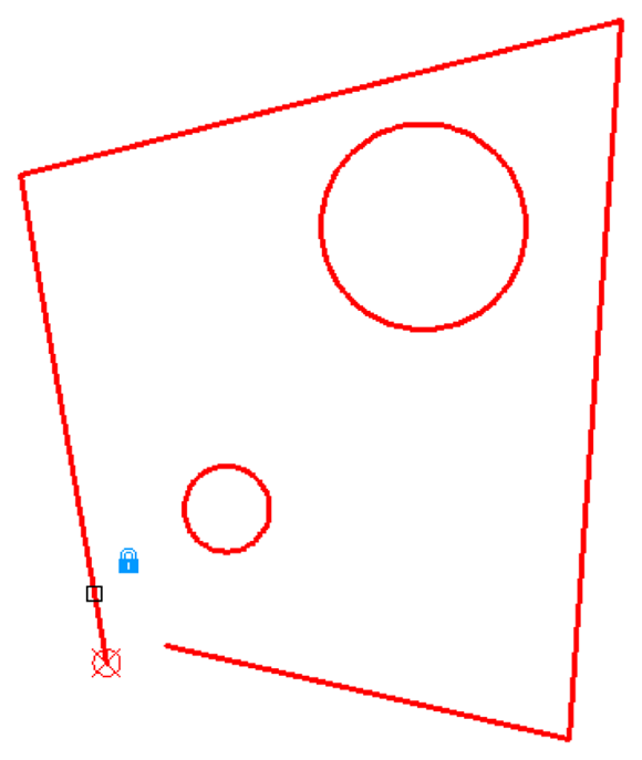
FIGURE 19-3: Locking down an object in drawing space.
 Click Coincident in the Parametric tab’s Geometric panel.
You use a coincident constraint to make two points coincide, such as the end points of two disconnected lines. A coincident icon appears near the pickbox. As you move the cursor over an object, the red X marker appears at points on which you can place the constraint. In the case of lines or polyline segments, they’re at the endpoints and the midpoint.
Use drawing commands appropriate for your design intent. I used a polyline in this example because the ends of the segments are already coincident-constrained by being part of a single polyline object. If you had drawn this shape with lines, you’d have to apply individual coincident constraints to each corner among the lines.Click an endpoint on the first polyline segment that you want to connect, and then click an endpoint on the second segment.
The endpoint of the second polyline segment jumps to the endpoint of the first line, and a small blue square (the marker for coincident constraints) appears at the intersection where this particular constraint was applied. If you don’t see the little blue square, click Show All in the Geometric panel.
 Apply some orthographic parameters so that the linework starts to look a little more like a rectangle. Click Horizontal in the Parametric tab’s Geometric panel, and then click a line or polyline segment that you want to align with the drawing’s X-axis.
In this example, we picked the bottom segment of the polyline. The segment realigns horizontally from the endpoint nearest to the spot where you picked the line (unless a Fix constraint is added first), and a horizontal constraint marker (a constraint bar) appears near the object. A single item is still called the constraint bar because, if you add additional constraints to the object, they’re added to the existing one, like a toolbar.
 Click Vertical to align a line or polyline segment with the drawing’s Y-axis.
In this example, we pick the left vertical(-ish) polyline segment. The segment realigns at 90 degrees to the horizontal segment, and a constraint bar showing a vertical constraint appears. With one line segment horizontally constrained and another vertically constrained, you’re halfway to a geometrically precise rectangle.
 Because rectangles have parallel and perpendicular sides, apply those constraints to your linework. Click Parallel in the Parametric tab’s Geometric panel, click the vertically constrained line segment, and then click the line segment opposite to it.
Because a vertical constraint is already applied to one segment, it doesn’t matter which line you pick first. If neither line had an existing constraint, the second line you picked would become parallel to the first line.
 Always prioritize your design intent as you consider which constraints to apply and in which order. As a general rule, start with the most important ones, and drill down to the least important. As I remind you earlier in this chapter, applying a fix constraint early in the game can prevent your geometry from rearranging itself in ways you don’t expect.
To make the final side of the almost-rectangle orthogonal with the other three, you could use another parallel constraint and click the bottom line. However, you don’t want to wear out the Parallel button, so use Perpendicular on the final segment.
 Click Perpendicular on the Geometric panel, click either vertical side, and then click the non-orthogonal side.
Again, because three of the four sides are already constrained to horizontal and vertical, it doesn’t matter which segment you pick first.
Perpendicular means “at right angles to.” It isn’t restricted to “a vertical line extending upward from one end of a horizontal line.” Lines drawn at an angle can still be perpendicular to one another, and the lines don’t even have to touch. Horizontal and vertical constraints work on one object, but parallel, tangent, and perpendicular constraints need two objects two work. When you roll the cursor over a constraint applied to two objects, its soul mate also lights up.To delete a constraint, move the mouse pointer over the constraint marker to display the constraints bar (see Figure 19-4), right-click, and choose Delete from the menu that appears.
From four non-orthogonal, not-even-closed line segments, applying a handful of constraints yields a perfect rectangle. However, you really want a square, which is where the Equal constraint comes in.
 Click Equal on the Geometric panel, click the bottom side, and then click either of the vertical sides.
It’s a perfect square! Now you have to constrain those circles.
The design intent in this example is to make the circles concentric and to locate their centers in the exact center of the rectangle. First, the easy part: Make the circles concentric.
 Click Concentric in the Geometric panel, click one circle, and then click the other.
The two circles are concentrically constrained. Try saying that ten times fast. A new constraint bar appears in their vicinity. Move one circle by clicking it, and watch the other tag along.
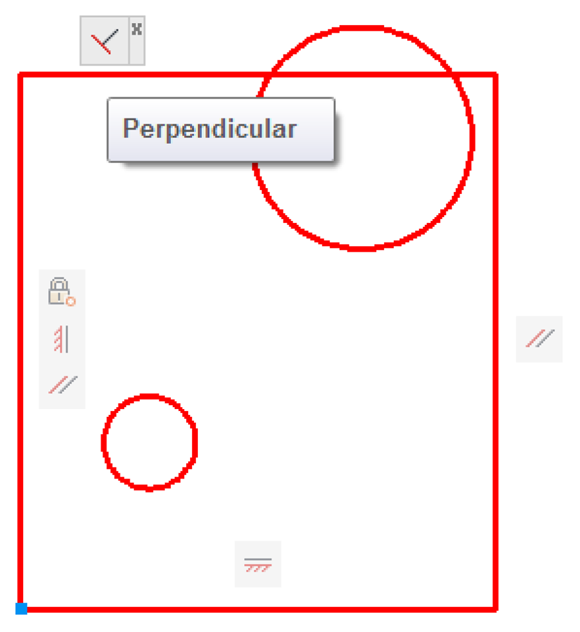
FIGURE 19-4: Constraining to orthogonal.
As I suggest, concentric is the easy constraint. I’d love to be able to use the Mid Between 2 Points object snap and simply click two diagonally opposite corners to locate the circles dead center in the rectangle. However, because you can constrain only objects or points on objects, you have to add some construction geometry to maintain the design intent.
Draw a line between diagonally opposite corners using Endpoint object snaps, and then apply coincident constraints between the endpoints of this line and the corners of the rectangle (see Figure 19-5).
Draw construction geometry on a separate layer, and set that layer to NoPlot in Layer Properties Manager. If you don’t want to even see your construction geometry (or plot it), turn off the construction geometry layer, or freeze it. The geometric constraints will still work.Click Coincident in the Geometric panel. Click either circle so that the parametric marker appears in the center, move the pickbox over the construction line, and click when the parametric marker is over the midpoint of the line.
You’re done! You can test your design intent by using the Stretch command on the corner of the rectangle that doesn’t display a square, blue coincident icon. As you drag the corner, you should see the two circles moving, too, always maintaining their position in the middle of the rectangle (see Figure 19-6).
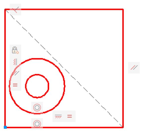
FIGURE 19-5: Adding construction geometry.
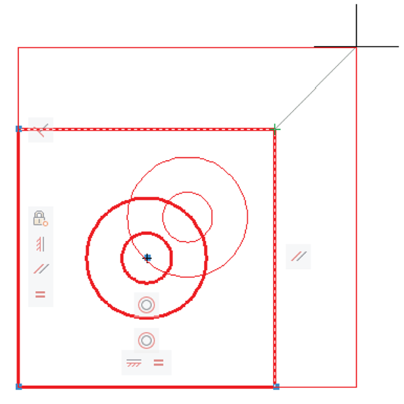
FIGURE 19-6: Full-on geometric constraints.
Using inferred constraints
![]() Parametrics were a new feature in AutoCAD 2010 and were considerably enhanced in AutoCAD 2011 by the addition of inferred constraints. A status bar button (to the left of the Snap button) toggles Infer Constraints mode off and on. When it’s on, you don’t have to specifically apply many of the geometric constraints.
Parametrics were a new feature in AutoCAD 2010 and were considerably enhanced in AutoCAD 2011 by the addition of inferred constraints. A status bar button (to the left of the Snap button) toggles Infer Constraints mode off and on. When it’s on, you don’t have to specifically apply many of the geometric constraints.
To produce the best results, go at least partway back to drawing with precision. For example, a coincident constraint is applied pretty much any time you use an object snap, and horizontal and vertical constraints are placed if polar or ortho modes are on.
Inferred constraints also work when editing existing geometry.
Inferred Constraints mode is a powerful component of parametric drafting in AutoCAD, but I recommend that you first familiarize yourself with manually applying constraints, as described in this chapter.
You AutoConstrain yourself!
The geometric constraints (refer to Table 19-1) are meant to be applied one at a time. That level of flexibility is helpful, but it can be pretty darned time-consuming to go around a complex object, trying to figure out what the best constraint option would be and then applying it.
![]() The Auto Constrain button on the Parametric tab’s Geometric panel can apply a whack of constraints to a selection of objects with a single click. Before you execute that click, however, take a look at the Auto Constrain settings. Click the dialog box launcher (the little angled arrow at the right end of the Geometric panel label) to open the Constraint Settings dialog box and make the AutoConstrain tab active (see Figure 19-7). Choose the constraints you want to apply automatically, and their order in the list, so that the ones that should take precedence have a higher priority. Your best bet initially is to stick with the defaults until you become more familiar with how Auto Constrain works.
The Auto Constrain button on the Parametric tab’s Geometric panel can apply a whack of constraints to a selection of objects with a single click. Before you execute that click, however, take a look at the Auto Constrain settings. Click the dialog box launcher (the little angled arrow at the right end of the Geometric panel label) to open the Constraint Settings dialog box and make the AutoConstrain tab active (see Figure 19-7). Choose the constraints you want to apply automatically, and their order in the list, so that the ones that should take precedence have a higher priority. Your best bet initially is to stick with the defaults until you become more familiar with how Auto Constrain works.
Auto Constrain works only with geometric constraints, not with dimensional constraints.
AutoCAD doesn’t let you overconstrain an object. For example, if a horizontal constraint appears on one line, and a parallel constraint appears between it and a second line, AutoCAD objects if you try to add a horizontal constraint to the second line.
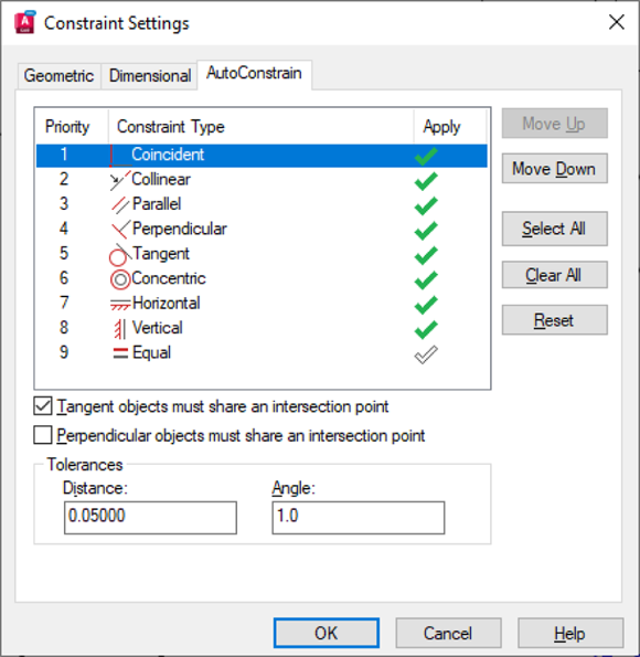
FIGURE 19-7: Auto-constrainable geometric relations in the Constraint Settings dialog box.
Understanding Dimensional Constraints
The normal practice in AutoCAD is first to create some geometry using, of course, the precision techniques I discuss in Chapter 8, and then apply dimensions as I describe in Chapter 14. Assuming that you’re using fully associative dimensions, you can edit the geometry and watch the dimensions update automatically. The length of the line or the radius of the circle is in control of the dimensions. These dimensions are known as driven dimensions because their values are updated by AutoCAD when you change the size or position of the objects.
Dimensional constraints, unlike regular AutoCAD dimensions, are driving dimensions — when you change the value of a dynamic dimension on a line, the line changes to match. In other words, the dimension is driving the length of the line, not the other way around. For instance, when you apply a dimensional constraints on the length of a line, you can move and rotate the line, but you can no longer change its length by dragging grips. Instead, you change its length by changing the value of the dimensional constraint.
There are only eight dimensional-constraint options, but they cover all the bases, as described in Table 19-2.
TABLE 19-2 Dimensional Constraints
Button | Constraint Name | What It Does |
|---|---|---|
| Linear | Applies a horizontal or vertical dimensional constraint (similar to DIMLINear) |
| Horizontal | Applies a dimensional constraint aligned with the X-axis of the coordinate system (similar to DIMLINear’s Horizontal option) |
| Vertical | Applies a dimensional constraint aligned with the Y-axis of the coordinate system (similar to DIMLINear’s Vertical option) |
| Aligned | Applies a dimensional constraint aligned with the object or with two points being dimensioned (similar to DIMALIgned) |
| Radial | Applies a dimensional constraint to the radius of an arc, a polyarc, or a circle (similar to DIMRADius) |
| Diameter | Applies a dimensional constraint to the diameter of an arc or a circle (similar to DIMDIAMeter) |
| Angular | Applies a dimensional constraint to the angle between two lines or three points (similar to DIMANGular) |
| Convert | Converts an existing associative dimension object to a dimensional constraint |
Practice a little constraint
The dimension-looking objects you add to a drawing from the Dimensional panel aren’t the same as the dimension objects you add from the Annotate tab. Dimensional constraints are driving dimensions — when you change the value of one of these dimensions, the linked geometry changes.
A lot is happening behind the scenes as you apply parametric constraints. You can get a sense of how these constraints work at keeping drawing objects in order by using the Stretch command on objects after you apply a constraint to them.
You can find the files I use in these steps at this book’s companion website: Go to www.dummies.com/go/autocadfd19 and download afd19.zip. The drawing named afd19a.dwg contains the unconstrained geometry, and the drawing named afd19b.dwg contains the end product.
These steps present a simple example of dimensional constraints:
- Start a new drawing and make the Ribbon’s Parametric tab current.
- Turn on the appropriate precision drawing aids on the status bar, such as Snap, Ortho, and Osnap.
Draw some reasonably precise geometry by applying the precision techniques I describe in earlier chapters.
In the following example, I use the RECtang and Circle commands to draw the geometry you see in Figure 19-8. The rectangle is ten units square, and the 2.5-unit-radius circle is deliberately drawn away from the middle of the square.
 On the Dimensional panel of the Parametric tab, click the top part of the Linear split button.
A linear dimension icon appears beside the pickbox, and AutoCAD prompts you to either specify the first constraint point or pick an object.
Like the DimLInear command, the Linear dimensional constraint tool is inferential — you create a horizontal or vertical dimension depending on which way you drag the cursor. Also, as with DimLInear, you can press Enter at the command line and select an object to dimension.
Hover the mouse over the Linear button to see (unlike its neighbor, Aligned) that the button is split into two parts. To force a linear dimensional constraint to be either horizontal or vertical (rather than dependent on the direction you drag the cursor), click the bottom part of the Linear button and choose from the drop-down menu.Press Enter at the command line to confirm that you want to select an object, and then select the bottom horizontal line segment.
If you see red markers at the midpoint and endpoints of the bottom line, you didn’t press Enter — and AutoCAD is in Point Selection mode rather than Object Selection mode.AutoCAD generates a preview of a dimensional constraint and prompts you for a location.
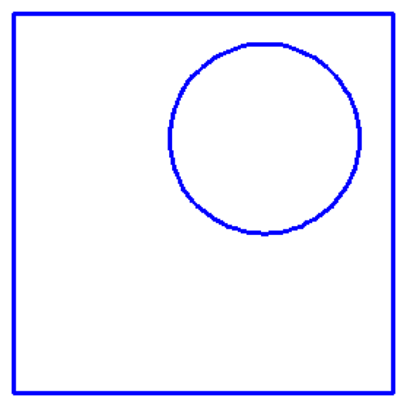
FIGURE 19-8: Simple geometry, badly in need of constraining.
Click to locate the dimension position.
AutoCAD draws a dimensional constraint with a highlighted text field displaying the dimension name (d1, in this example) and the value returned by AutoCAD.
Press Enter to confirm the value and the dimension location (see Figure 19-9).
Best practice is usually to accept the default value for all dimensional constraints as they are applied and then edit them later to the exact values that are desired. This avoids problems like trying to make the width of a slot greater than the width of the piece that contains the slot, which can turn your drawing inside out. If dimensional constraints disappear as soon as you place them, click the Show All button on the Parametric tab’s Dimensional panel (refer to Figure 19-1). Because dimensional constraints aren’t regular dimension objects, you can’t apply dimensions styles and you can’t plot them, so it doesn’t matter where you put them or what they look like. In fact, AutoCAD automatically resizes them appropriately as you zoom in and out of the drawing so that you can always read the text. I show you in the next section how to turn dimensional constraints into properly styled, plotable dimensions.Repeat Steps 4–6 and add a dimensional constraint to the rightmost vertical edge of the rectangle.
AutoCAD draws a second dimensional constraint, this one named d2.
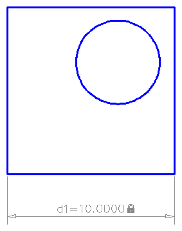
FIGURE 19-9: Placing a dimensional constraint.
Making your drawing even smarter
If your drawing were a traditional mechanical drawing that followed the rules of drafting, the placement of a horizontal and vertical dimension in the example of the previous section would be enough. Whoever reads your drawing understands that if sides look parallel and perpendicular, a dimension on one side applies to the opposite side as well. But in this chapter, I talk about intelligent drawings that respect design intent — not dumb collections of lines and circles, even if they do follow the rules of drafting.
If you stretch a rectangle in various ways (from the upper-left corner, for example), you can see that only the bottom and right sides are constrained to 10 units in length. You can add two more linear dimensional constraints to the unconstrained sides, but then you’d have to remember to edit both dimensions. Rather than constrain both sides to be 10 units long, you maintain design intent by making both sides equal in length.
You can make the two sides equal by using either dimensional or geometric constraints. You should usually apply most, or all, of the geometric constraints to the drawing before adding dimensional constraints. This way, the objects behave in a more predictable manner when you change the dimension values.
Follow these steps to apply three geometric constraints:
- On the Geometric panel of the Parametric tab, click Fix (the padlock icon) and then click the lower-left corner of the rectangle.
- On the Geometric panel, click Horizontal and click the bottom side of the rectangle. Then click Vertical and click the left side.
Icons appear near the drawing geometry, showing that those three geometric constraints are active.
- On the Dimensional panel of the Parametric tab, click Linear and add a dimensional constraint to the top horizontal line.
Click to locate the dimension, type d1, and then press Enter when AutoCAD prompts you for the dimension text.
Rather than display numeric values, like the first two linear constraints, this new dimensional constraint displays
fx: d3=d1. The main part of this expression sets the d3 dimension to equal the value of the d1 dimension. The
 fx:is short for “formula” and reminds you that other variables in other dimensions are being referenced.Repeat Steps 3 and 4, and this time add a constraint to the vertical line at the left. Then enter d2 as the dimension text.
All four dynamic dimensional constraints display their names and a value or expression for each one.
Dimensional constraints have names as well as values; the values can be expressions or formulas. You can set the default appearance of dynamic dimensional constraints by clicking the dialog box launcher (the little arrow at the right end of the Dimensional panel label) to open the Constraint Settings dialog box, with the Dimensional tab active (see Figure 19-10).
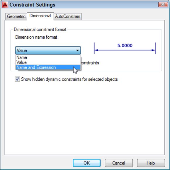
FIGURE 19-10: Format the appearance of dimensional constraints in the Constraint Settings dialog box.
The options are as follows:
- Name: The first linear dimension is named d1, the second d2, and so on. You use the dimension names in expressions.
- Value: The numeric value that you enter into the dimensional constraint (or that AutoCAD enters if you don’t override it).
- Name and Expression: The dimension name shown as equal to an expression. The expression can be a value, as in this example, or it can be a formula that includes other dimension names.
Using Parameters Manager
Both AutoCAD and AutoCAD LT include the Parameters Manager palette, accessible from the Manage panels of the Ribbon’s Parametric tab. You can use Parameters Manager to give all those dimensional constraints more sensible names than d1 and d2, but you can (even more usefully) enter expressions instead of plain numeric values, as I explain in these steps:
 Click Parameters Manager in the Manage panel.
The Parameters Manager palette appears, showing a list of the dimensional constraints applied in the drawing (see Figure 19-11).
In Figure 19-11, the Expression column shows the numeric values that I specified for
d1andd2and the expressions I entered ford3andd4. The read-only Value column shows the calculated value. You can’t change a value in the Value column (it’s grayed out to remind you). You can only edit the cells in the Expression column.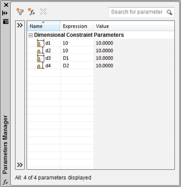
FIGURE 19-11: The Parameters Manager palette.
In the
d1row, click in the Expression field to highlight the current value (10, in this example). Then click again and type a new value. For example, type 13 and press Enter.The rectangle resizes in the drawing editor, and because the
d3constraint on the top side was made equal to thed1constraint on the bottom side, both sides change equally.Next, you use an equation as an expression.
In the
d2row, click in the Expression field to highlight the current value, and then type an expression. For example, type d1*0.75 and then press Enter.The read-only Value column and the drawing geometry show that the new
d1distance of 13 has been multiplied by 0.75 and is now 9.75 (see Figure 19-12).Close Parameters Manager.
Constrain the circle so that its center is always at dead center in the rectangle, no matter how the rectangle’s size changes.
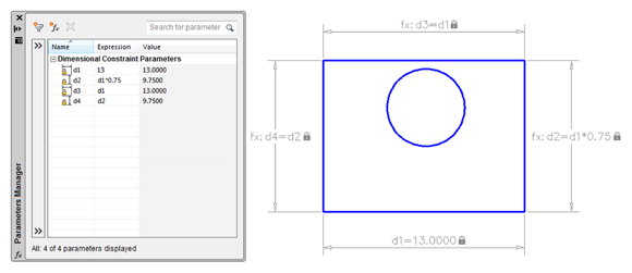
FIGURE 19-12: Editing constraints in Parameters Manager.
Apply a horizontal dimensional constraint from the upper-left corner of the rectangle to the center of the circle. Locate the dimension, type d3/2, and then press Enter.
Because the rectangle is now dimensionally constrained on all four sides, it doesn’t matter which corner you start from. Note that you don’t have to type the whole expression:
d5=d3/2. AutoCAD knows what you mean!Repeat Step 5, and this time add a vertical constraint from one corner to the center of the circle. Locate the dimension, and then type d4/2.
Figure 19-13 shows the object geometry with all constraints added in this section. Who knew that drafting could be such fun?
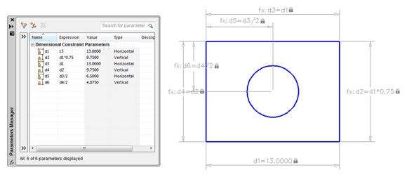
FIGURE 19-13: All locked down — dimensionally, at least.
If your drawing becomes overrun with parameters, you can add parameter filters in the Parameters Manager palette. Right-click any parameter and choose Show Filter Tree, or click the double right arrow at the left of the palette to open the Filters pane. Click the funnel icon on the toolbar to create a new filter group, and then simply drag and drop parameters into the group. Figure 19-14 shows the two constraints (refer to Steps 5 and 6 of the preceding step list) dragged into a new group filter.
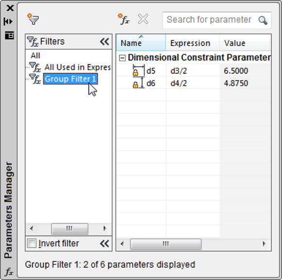
FIGURE 19-14: Filter parameters to keep them organized.
Dimensions or constraints? Have it both ways!
After all the hard work of adding dimensional constraints to a drawing, it would be a downright shame to have to go back and apply regular dimensions, wouldn’t it? Well, you don’t have to. You can make dimensional constraints look and behave like regular dimensions. You can go the other way, too, and make your regular dimensions act like dimensional constraints.
Dimensional constraints are available in two flavors:
- Dynamic: In this default form, a dynamic constraint is gray, with a padlock icon next to it in the drawing area. You can make the constraint appear and disappear by clicking Show All in the Dimensional panel. Dynamic constraints don’t plot, and they’re always legible because they resize as you zoom in and out of the drawing.
- Annotational: This form is controlled as an object property, so you have to set it in the Properties palette. Though annotational constraints plot, they don’t resize as you zoom in and out, and they don’t disappear as you toggle the Show All button on and off. Annotational constraints conform to dimension style settings.
The dimension name format of annotational constraints can be set to Name, Value, or Name and Expression, just like dynamic constraints. Refer to Figure 19-10 for another look at the Constraint Settings dialog box. If you want to plot a drawing with annotational constraints, reset the format so that it doesn’t show the dimension name or the expression.
Here’s how to turn dynamic dimensional constraints into annotational constraints:
Open a drawing that contains some geometry with dimensional constraints.
You can also start a new drawing, draw some simple geometry, and add a dimensional constraint or two.
Select a dynamic constraint, right-click, and choose Properties.
The Properties palette opens with the object properties of the selected dimensional constraint listed in table form.
Click in the Constraint Form field, and in the drop-down list, change Dynamic to Annotational (see Figure 19-15).
The dynamic constraint becomes annotational and takes on the appearance of the current dimension style. If you change the dimension style in the Properties palette, the annotational constraint updates to the new dimension style format.
You can go the other way, too — from regular dimension objects to dimensional constraints to convert an existing dumb drawing to an intelligent parametric one.
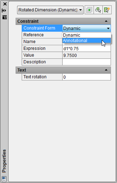
FIGURE 19-15: Turning dynamic constraints into annotational ones.
Add a linear, radius, diameter, aligned, or angular dimension (that is, a regular dimension, not a dimensional parameter) to your drawing geometry.
Nearly every type of dimension object has a parametric analog; the exceptions are arc length, jogged radius, jogged linear, and ordinate dimensions.
 Click Convert in the Dimensional panel, select a dimension type (refer to Step 4), and press Enter.
The Dimensional Constraint text box displays as soon as you click an associative dimension, and the dimension becomes a dynamic constraint as soon as you press Enter.
The only clue that a dimension is an annotational constraint rather than a regular associative dimension is the padlock icon that appears next to the dimension value. You can turn off the display of the padlock from the Constraint Settings dialog box, but I recommend that you leave it on. It doesn’t plot anyway, and you might decide to delete the dimension without realizing that it’s controlling your object geometry.
Annotational dimensions can also be annotative so that they size themselves automatically to the drawing scale. I cover annotative dimensions in Chapter 14. Annotative and annotational dimensions are also associative, so you can have annotative annotational associative dimensions. Try saying that quickly after a few drinks.
In this chapter, I present the two varieties of parametric constraints separately, but you get the most mileage from this feature when you incorporate both geometric and dimensional constraints with other precision techniques (described in Chapter 8). In fact, if you start a drawing by using Snap, Ortho, Osnap, and other precision techniques before you add dimensional and parametric constraints, you’ll be well on your way to creating a library of intelligent drawings that maintain your design intent.
Geometric and dimensional constraints can be equivalent. For example, a 90-degree-angle dimensional constraint is equal to a perpendicular geometric constraint, but AutoCAD doesn’t let you apply both.
All examples in this chapter involve a single drawing view. Geometric constraints apply “to infinity,” so you can synchronize objects from one orthographic view with objects in another. For example, coincident and collinear constraints can link objects in the front view with their equivalents in the top and right-side views, and liberal use of the equal constraint means that you should never have to measure or dimension anything twice, you should never need more than minimal construction geometry, any changes in one view reflect through to the others, and your views always remain orthogonally aligned.
Lunchtime!
You may recall that in the opening paragraphs I laid out a scenario wherein your boss instructed you to make a number of changes, and I implied that you could do them almost instantaneously. If you haven’t already done so, go to www.dummies.com/go/autocadfd19 and download afd19.zip. Open the drawing named afd19e.dwg, which looks like Figure 19-16.
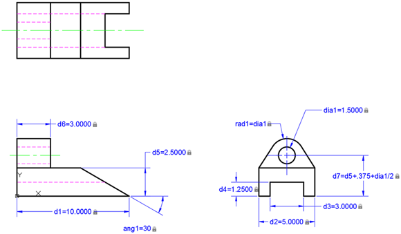
FIGURE 19-16: This part needs a few revisions.
Now double-click the dia=1.5000 dimension and change it to dia1=2.0000 and then press Enter. Surprise! Two more dimensions change and all three views update! While you're at it, change ang1=30 to ang1=60, change d5=2.5000 to d5=2.000, change d6=3.0000 to d6=2.5000, and change d1=10.000 to 8.1250. Then print your drawing and head to the door to meet your boss and the client with a drawing that looks like Figure 19-17.
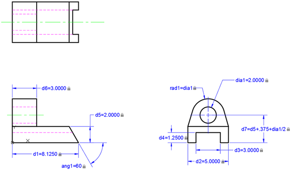
FIGURE 19-17: Thirty seconds later …