Chapter 23
It’s Showtime!
IN THIS CHAPTER
![]() Creating 2D working drawings from 3D models
Creating 2D working drawings from 3D models
![]() Visualizing 3D models
Visualizing 3D models
![]() Lighting your models
Lighting your models
![]() Applying materials
Applying materials
![]() Assigning a background
Assigning a background
![]() Applying render presets to 3D models
Applying render presets to 3D models
The word design has the same Latin origin as designate: “to point out to or to show to others.” If you have an idea and produce it yourself, you aren’t a designer — you’re an artist or a craftsman (nothing wrong with that!). You don’t become a designer until you tell other people about your idea so that they can do all the dirty, heavy work of producing it.
Two-dimensional orthographic drawings date to Roman times, but only in the past few years have I seen a significant change in how things are designed — and how designers communicate their visions to others. No, I don’t mean 2D CAD on a computer, because that’s simply a more efficient way of producing Roman-era drawings. The world we live in is 3D, but paper is 2D. Orthographic engineering drawings, which show the left, front, top, and so on sides, were developed for the sole purpose of transferring the designer’s 3D idea into 2D format. The recipient of the drawing then transfers the idea back into 3D, first as an image in the mind and then as the physical object.
The significant change occurred when personal computers became inexpensive enough and powerful enough and software become sophisticated enough that designers could work in 3D on their own computers, including laptops. Around the same time, 3D printers became available to take the 3D model on your computer and produce a real-world object. This type of printer was developed with mechanical designs in mind, but architectural designers use it to print scale models of their buildings. More recently, the scale factor for printing buildings has become 1:1. That’s right: Full-scale concrete multi-story apartment blocks are being printed in 3D directly from the computer model! However, the real world still needs (or at least wants) 2D drawings.
Combining relatively low-cost computers with powerful software made it possible for designers to produce photorealistic rendered images of their 3D models. Clients and customers are keen to see the product before it becomes real.
I start this chapter by showing you how to generate 2D drawings from 3D models, and then move on to discuss rendering of 3D models.
Get the 2D Out of Here!
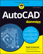
Would you believe that it took less than five minutes to produce Figure 23-1?
FIGURE 23-1: A drawing, in less than five minutes!
Follow these steps to produce a 2D view from a 3D model. There are several ways to approach this task; I show you the quickest:
 Click the Workspace Switching button on the status bar, and then choose 3D Modeling.
Ribbon tabs flash on and off, and soon AutoCAD settles down to display the Ribbon, as configured for the 3D Modeling workspace with a few additional panels.
Set up a 3D model.
Create a new model by using the techniques I discuss in Chapters 21 and 22, or open an existing file that contains a 3D model.
You can find the files I use in this step list at this book’s companion website: Go to
www.dummies.com/go/autocadfd19and downloadafd23.zip. The drawing namedafd23a.dwgcontains the model I use in the following steps.Switch to paper space.
Click the Layout 1 tab near the lower-left corner of the screen.
Delete the existing viewport by clicking the viewport object (the frame of the viewport) and then pressing Delete.
By default, new drawings created from a standard template file contain a single viewport. If you find that you create new drawings like this one frequently, set up a template file with the viewport already deleted. I cover templates in Chapter 4 and paper space layout viewports in Chapter 12.
 Click the Base button from the Create View panel on the blue Layout contextual tab of the Ribbon, and then choose From Model Space in the drop-down list.
 The VIEWBASE command creates two new layers automatically, one for visible lines and the other for lines that could be shown with the hidden linetype. By default, they’re the opposite of the screen color (black or white), but they always print in black. You can change these layers to any color you want (see Chapter 9).
Position the base view.
Pick a suitable place in the upper-left quadrant of the layout sheet. AutoCAD selects what it thinks is an appropriate scale automatically. The size of the views is based on the assumption that you’ll want to fit four views of the 3D model onto this sheet — the three standard orthographic views and one pictorial (isometric) view. You can change the scale later if you want.
The blue Drawing View Creation contextual tab appears on the Ribbon (as shown in Figure 23-2), a drop-down list of view options appears at the cursor, and an option list appears on the command line.
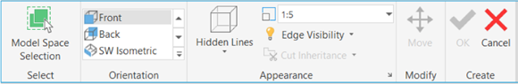
FIGURE 23-2: The Drawing View Creation context tab of the Ribbon.
Define the base view.
The base view is the initial 2D drawing made from the 3D model; the other 2D drawings are based on it.
Using any one of the user interfaces — at the Ribbon, with the dynamic input menu, or through the command line prompts — set up the base view as follows:
- Orientation: The view shows what appears to be the bottom view of the part, because AutoCAD defines the top, bottom, and so on relative to the world X,Y coordinates. Select Orientation and then Top to place the top view of the 3D model.
- Hidden lines: The preview images of the 3D model always appear in shaded mode as you place the views, regardless of the visual style of the model in model space. Change the Hidden Lines option to Visible and Hidden. The view won’t change yet, but don’t worry — it will after you complete these steps.
- Scale: This setting defaults to 1:4, which is suitable for your purposes if you started from our sample drawing.
- Visibility, or Edge Visibility: This setting specifies how to display the edges that are formed where tangent surfaces meet. The normal practice is not to display them, but it sometimes causes features to disappear (or partially disappear). If you want to change this setting, hover the cursor over the Edge Visibility button in the Appearance panel of the Ribbon and pause for a few seconds; a much more extensive tooltip list then explains each option.
- Move: Specify a new location for the view before it is finally created. This isn’t such a big deal, though, because views can always be easily moved later.
- Exit: Or press Enter.
You can edit all these view options later, view by view.Place more drawing views below and to the sides of the first one.
 When you finish placing and defining the initial base view, AutoCAD automatically starts the VIEWPROJ command, and all you need are three quick clicks to place the top, isometric, and right-side views. Press Enter to have AutoCAD generate the hidden-line views.
Edit the isometric projection.
Isometric projections don’t normally show hidden lines. Double-click anywhere in the isometric projection to bring up the Drawing View Editor tab on the Ribbon, as shown in Figure 23-3.
Click Hidden Lines on the Appearance tab and choose Shaded with Visible Lines from the drop-down list.
 If a Ribbon button has a drop-down list, the Ribbon displays the last button that was used. Any one of four different buttons may be in this particular location.
Figure 23-4 shows three ortho views and a shaded isomeric view, which I created in 37.6 seconds.
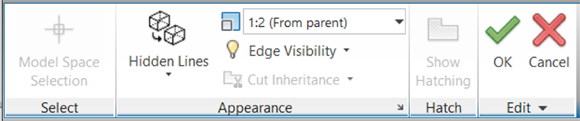
FIGURE 23-3: The Drawing View Editor context tab on the Ribbon.
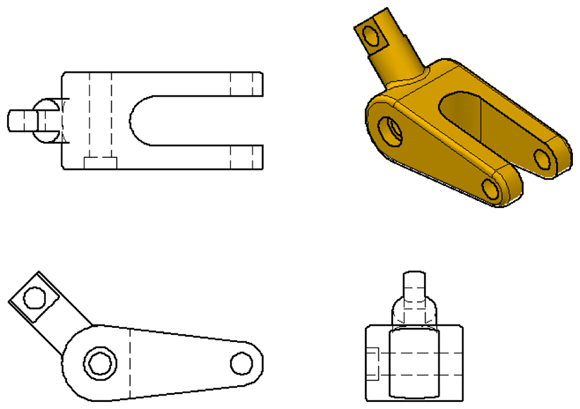
FIGURE 23-4: Average creation time: 9.4 seconds per view.
Add annotations.
Add dimensions and text notes in the paper space layout. Dimensions are associative to their matching geometry if you use object snaps to the geometry when you place them. I cover object snaps in Chapter 8, text in Chapter 13, and dimensions in Chapter 14. While you’re at it, perhaps you can try using VIEWDETAIL to create a detail view at a different scale.
When you submit a drawing to your boss, he or she will be impressed that you managed to create such a complex drawing, including the shaded isometric projection, in only three days.
Always place text and dimensions on their own layers. I discuss layers in Chapter 9.
 An isometric view and an isometric projection are different creatures. An isometric view is normally drawn so that lines that are parallel to the three principal axes appear in their true length, and an isometric projection foreshortens them due to the tilting and rotating of the viewing angle of the object. Traditional paper-and-pencil drawings use isometric views, whereas AutoCAD creates isometric projections.
If you truly want an isometric view, the solution is simply to ignore the usual rule about drawing and inserting at full size. When creating an isometric projection, use this approximate scale factor to produce an isometric view:
1.2247441227836356744839797834917
You can also edit the insertion later, to make it match this scale factor.
A different point of view
You can edit 2D views that were generated from 3D models in two ways. The easy way is to edit the view specifications themselves:
- Select the base view, and then select the blue grip box that appears in the center of the view.
Drag and drop the view into a new location.
Interesting! If you move the base view, all the ortho views projected from it follow along, with some limitations. The ortho views don’t move in perfect unison as a single group, but they maintain their orthographic relationship to the base view.
Similarly, you can move projected ortho views in only the direction that still maintains their ortho relationship to the base view.
Better yet, all attached dimensions (you hope) also follow along.
The second way is to double-click a view and then change the specifications that were used to create it. Refer to Step 9 in the step list in the preceding section.
To experience the magic of AutoCAD automatically associating 2D views with the 3D model, return to model space and edit the model. For example, add a second hole (hint: subtract a cylinder) and extend the length of the peg. Return to the paper space layout. All your views and their dimensions are updated, as shown in Figure 23-5.
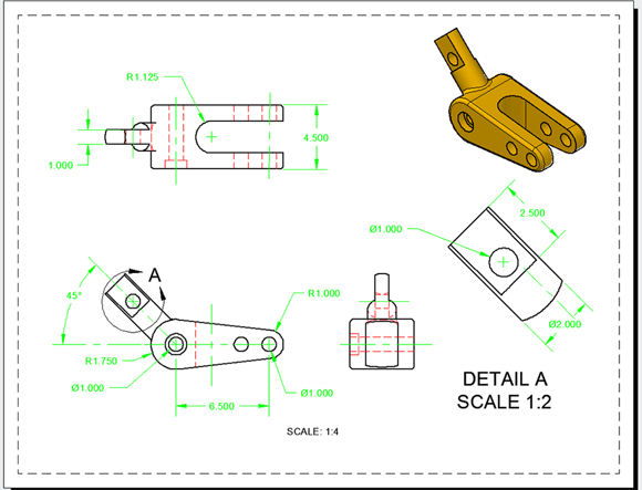
FIGURE 23-5: When anything changes, everything changes.
Behind the scenes, AutoCAD creates the views as a series of anonymous blocks. They behave much like regular blocks, but because they don’t have normal names, you can’t access them directly to edit or explode them. I discuss blocks in Chapter 17.
Additional 3D tricks
In earlier sections of this chapter, I only touch on the 3D-to-2D capabilities of AutoCAD — although, if you’re reading the entire chapter, I may have whetted your appetite for more. To fully cover the 3D capabilities of AutoCAD would easily require a full book on its own (AutoCAD 3D For Dummies, perhaps?), but meanwhile, here are a few high points:
- Don’t want four views? If you don’t want four standard views, create only the base view and the one or two additional views you want. Then change their scale factor to better suit the sheet size.
- Need additional base views? If necessary, you can have more than one base view in a single layout. For example, one large drawing might show an assembly and its component parts. Just rerun the VIEWBASE command.
- Didn’t create enough views? Use the VIEWPROJ command to add more projected views later. They don’t have to project from the original base view, but can project from an existing projected view.
- No longer need a view? You can delete a view, even a base view, without affecting the other views — except that doing so breaks the horizontal and vertical links between the views that were projected from it. Select a view and then press the Delete key.
- No 3D model in your drawing? Earlier in this chapter, I used the VIEWBASE command to generate views from a 3D model that lived in the model space of the current drawing. AutoCAD 2013 introduced functionality so significant that it deserves more explanation, which I happily provide in the next section of this chapter.
AutoCAD’s top model
You may have generated 2D drawing views from a 3D model in model space in the earlier section “Get the 2D Out of Here.” But if the VIEWBASE command cannot find a 3D model in the current drawing file, it opens a standard file dialog box so that you can browse for an Autodesk Inventor part or assembly file.
Autodesk Inventor is the 3D parametric modeling software from Autodesk primarily intended for the mechanical design field. Inventor is fully parametric: Dimensional constraints drive 2D profiles that define the solid features that consist of the parts that comprise the assembly model that drives the 2D drawing views that Jack built. If you change a dimension on a 2D drawing of a part, everything updates, all the way down the line.
AutoCAD accepts Autodesk Inventor files during the VIEWBASE command. The Inventor file isn’t inserted into the AutoCAD file but is attached like an xref. I cover xrefs and DWG files in Chapter 18. VIEWBASE creates a 2D drawing view based on it, and additional views can be projected from the base view.
Here’s the magic part: The AutoCAD drawing views are linked to the Autodesk Inventor file so that any changes made to the Inventor file are reflected in the AutoCAD file, updating it. On the other hand, whenever the AutoCAD DWG file has access to the Inventor file, the AutoCAD drawing views update and remain in step with any changes made to the Inventor model. (The AutoCAD file contains only anonymous blocks for the 2D views and has nothing in model space.)
Better yet, you can send the AutoCAD DWG file to a client or vendor without having to send the source Inventor file.
Here are more tips for working with AutoCAD and Inventor files:
- Mix and match 2D drawing views. You can have more than one base view in an AutoCAD drawing, so you can mix and match 2D drawing views. One or more base views can come from an internal AutoCAD 3D model, and others can be linked to external Inventor files. If VIEWBASE finds an AutoCAD solid in your part, you can tell it to ignore it and attach it to an Inventor file instead. For example, you might have a mechanism assembly drawing consisting of several 3D parts, of which one is a simplified conceptual part. When you create 2D drawing views, you can tell AutoCAD to ignore the simplified part and instead link it to the more complex and detailed Inventor model.
- Select additional solids. When model space contains more than one solid, VIEWBASE allows you to switch back to model space to select and deselect solids to appear in the base view. For example, a model of a gearbox assembly might consist of many components. Separate views can be created, perhaps on several different layouts: one showing an outside view of the entire gearbox (which doesn’t need to include the internals such as gears and bearings); another showing only the input shaft, gear, bearings, and seals; and another showing the output shaft and its related components.
- Choose a different scale. The VIEWDETAIL command generates detail views at scales different from the parent view, which matches standard drafting practice.
- Use different section views. The VIEWSECTION command has five options for creating section views: Full, Half, Offset, Aligned, and From Object. This command creates section views based on existing views in the layout. The cutting plane line that it generates can be manipulated like any regular polyline, and the section view then updates accordingly.
Visualizing the Digital World
Rendering allows you to see how a final product might look before it’s manufactured or built in the real world (see Figure 23-6); it definitely helps to sell concepts to clients. Although you can show a client hidden line and shaded views of 3D models, showing a series of photorealistic renders helps make it feel that much more real.
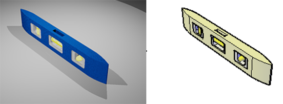
FIGURE 23-6: Rendering compared with the Conceptual visual style.
Before rendering a 3D model, you should
- Add lights to highlight features and define shadow types.
- Apply materials to 3D objects by face, object, or layer.
- Set a background to your 3D model
All these actions bring realism to a 3D model. This chapter focuses next on each of these tasks and then explains the steps to create a rendering.
Adding Lights
One key ingredient that makes renderings look good is lighting. Lighting helps give a model depth by applying highlights and shadows. As in the real world, objects that are closest to the light source appear the brightest, and objects the farthest distance away appear darker.
AutoCAD uses both default and user-defined lighting. Default lighting, as its name suggests, is on and available in every drawing. It uses two lights to give basic form to your 3D model when you click the Render button. User-defined lights can cast shadows.
Most tools that you use to create and edit lights are located on the Lights panel and the Sun & Location panel on the Render tab.
Default lighting
Over the years, AutoCAD’s default lighting has improved in quality. Before AutoCAD 2007, default lighting consisted of a single, distant light source, always directed toward the target of the current view from behind your back. AutoCAD 2007 added a second default light to help increase the lighting level, and to balance the lighting in a viewport.
Default lighting can’t cast shadows, so I don’t recommend using it for final renderings. It does, however, work pretty well for quick conceptual renderings. You have control over the brightness, contrast, and midtone levels for default lighting by using the slider controls on the slideout of the Lights panel on the Visualize tab of the Ribbon (see Figure 23-7). AutoCAD 2014 and earlier have these controls on the Render tab of the Ribbon.
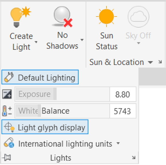
FIGURE 23-7: AutoCAD to lights; extra brightness is a go.
Use the DEFAULTLIGHTING system variable to enable and disable the use of default lighting in the current viewport. Set DEFAULTLIGHTING to 0 when you want user-defined lighting to render your 3D model. If you’re using default lighting, the DEFAULTLIGHTINGTYPE system variable controls whether one or two default distant lights are used: When set to 0, one default light is used; when set to 1, two default lights are used.
User-defined lights
Default lights are fine for quick renderings, but they don’t bring renderings to life in the way that user-defined lights can. User-defined lights are lights that you create (with one exception) and modify in your 3D model. The only user-definable light type that you can enable and modify, but not create, is the sunlight system — someone else already created it.
The first time you use a user-defined light in a drawing, the Lighting – Viewport Lighting Mode alert box is displayed, advising you to turn off default lighting in order to see light from user-defined sources. You can have only one type — default or non-default — so click Turn Off the Default Lighting to disable the default lighting. (To turn default lights back on, open the Lights panel slideout on the Render tab and click Default Lighting.)
You can create two types of user-defined lights:
- Generic: This type provides many controls over how the light should be emitted.
- Photometric: This type is more sophisticated because it mimics the way actual lights illuminate the physical world.
The LIGHTINGUNITS system variable controls whether user-defined lights in a drawing are represented as generic or photometric. When LIGHTINGUNITS is set to 0, generic lights are used; when LIGHTINGUNITS is set to 1 or 2, photometric lights are used — 1 indicates American lighting units, and 2 indicates international lighting units. Lights don’t have to be removed and added to switch between generic and photometric lights; you only need to switch the system variable.
To add a user-defined light to a drawing, click the lower half of the Create Light split button on the Lights panel of the Render tab. You can choose from four distinct types of lights on the flyout (you can see the differences between light types in Figure 23-8):
 Point light: Emits light uniformly in all directions, similar to a candle or a light bulb. The light emitted falls off as it moves farther from the source.
 Spotlight: Emits light in a one direction, like the ones used at concerts. As light travels away from the source, it spreads out in the shape of a cone. You can define the hotspot (the brightest part in the center of the emitted light) and a fall-off for the light.
 Distant light: Emits light along a specified vector and doesn’t decay or fall off, like other user-defined lights do. A distant light is similar to the sun.
 Weblight: Has nothing to do with spiders or the internet. Weblight is the name for photometric lights, and the name is based on the uneven pattern that real lights emit. The way weblights illuminate rooms and outdoor areas is determined by IES (Illuminating Engineering Society) files, which are provided by light manufacturing companies. Search the internet for photometric lighting to find weblight or IES light definition files from manufacturers.
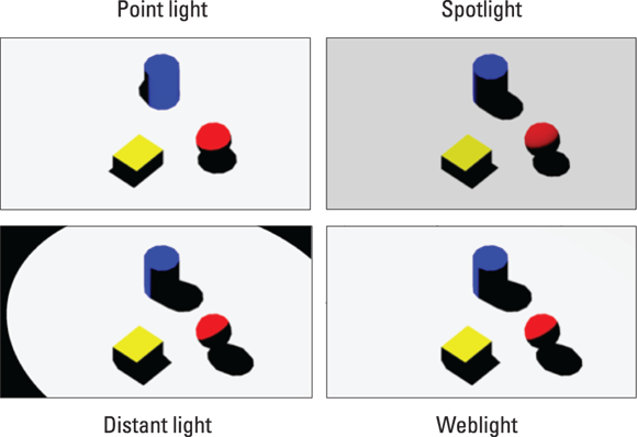
FIGURE 23-8: Lighting primitives with the four types of user-defined lights.
 AutoCAD — and I — strongly advise against using distant lights when using photometric lighting. If you decide to ignore this warning, turn down the intensity factor of the distant light to avoid washing out the rendering.
Point lights, spotlights, and weblights can be selected and edited directly in a drawing because a glyph is displayed to show where the light is located. Distant lights have no associated glyph. A glyph is a nonprinting object displayed in a drawing that enables you to select an object that isn’t part of the actual model.
To avoid some of the frustration of applying lights, visit a portrait studio, have your portrait taken, and notice how the lights are set up. A brighter light is typically placed (about 45 degrees) above and (about 45 degrees) to one side of the camera as you face it, and a second, dimmer light is placed lower (about 30 degrees) and on the other side of the camera.
The shadow knows…
AutoCAD allows you to define lights that don’t generate shadows. Though this statement might seem illogical because shadows are cast when light is obscured by an object, it’s important because you may want to fill an area with light but not have it affect the way shadows are cast.
To control the shadows generated by lights, select a light, right-click, and then choose Properties to open the Properties palette. The Shadows option in the General category enables or disables shadow creation from the selected light. The Rendered Shadow Details category gives you a large degree of creative control over shadow appearance. For more information on putting objects in the shade, open the online Help system and search for Render 3D objects for shadows.
You can also control how objects themselves affect shadows. Select a 3D object, right-click, and choose Properties. In the 3D Visualization category of the Properties palette, click the Shadow Display drop-down list. You can configure objects to cast shadows, receive shadows, cast and receive shadows, or ignore shadows altogether.
The Lights in Model palette
You can use the Lights in Model palette (see Figure 23-9) to select, delete, and access the Properties palette for selected lights. The palette is especially handy for the distant light, which doesn’t display a glyph for you to edit because it's located at infinity. To display this palette, click the Lights panel launcher (the little arrow at the right end of the Lights panel label).
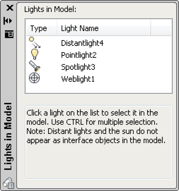
FIGURE 23-9: Ah, yes, you’re on the lights list.
Sunlight
You control the way sunlight affects your 3D model through the Sun Properties palette (see Figure 23-10). Adding sunlight to a drawing and then specifying the date, time, and geographic location allows you to perform sunlight studies. Sunlight adds realism to both indoor and outdoor renderings.
![]() You use the Sun Properties palette to locate the sun’s position based on the nearest large city or on latitude and longitude values. You can also use KML or KMZ files exported from Google Earth to specify a location. In addition to location, you can designate the northern direction to find the correct daily movement of the sunlight in your drawing. To adjust the sunlight in a drawing, open the Sun Properties palette by clicking the Sun & Location panel launcher (the little arrow on the panel label).
You use the Sun Properties palette to locate the sun’s position based on the nearest large city or on latitude and longitude values. You can also use KML or KMZ files exported from Google Earth to specify a location. In addition to location, you can designate the northern direction to find the correct daily movement of the sunlight in your drawing. To adjust the sunlight in a drawing, open the Sun Properties palette by clicking the Sun & Location panel launcher (the little arrow on the panel label).
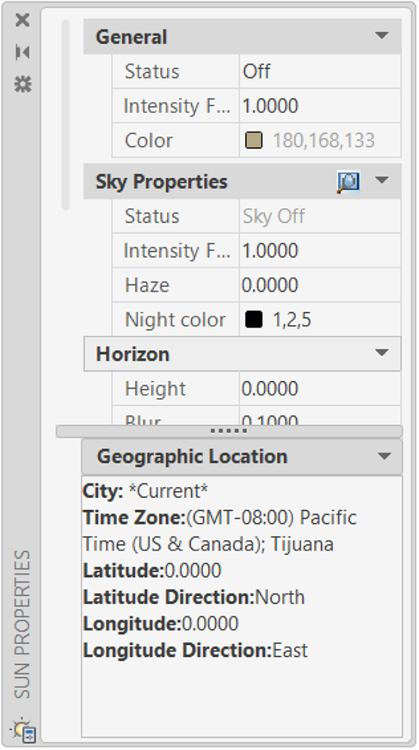
FIGURE 23-10: The Sun Properties palette gives you the power to control day and night.
Creating and Applying Materials
Materials, even more so than lights, bring your models to life. Materials can be as simple as glossy paint, or as complex as rough bricks, or anything in between. You can apply representations of realistic, real-world materials like stone, marble, glass, wood, metal, and fabric — the list is almost endless. The materials can be opaque, transparent, reflective, or nonreflective. AutoCAD comes supplied with a material library of literally thousands of material types. Assigning them to objects can be as simple as dragging a material from a palette and dropping it on an object. Or you can define your own materials as complex as you care to make them.
Before AutoCAD 2011, you created and stored materials in individual drawings, which made them difficult to manage. AutoCAD 2011 introduced Materials Browser, which makes managing materials much easier. Material definitions, which live in a central repository, are attached to each drawing as an external reference.
All Autodesk products that use material definitions use the same central library, so a model rendered in AutoCAD looks the same as one done in other Autodesk programs like Inventor, Maya, and 3ds Max.
The partner to Materials Browser is Materials Editor, which edits the properties of materials to define their look. It's accessible from a button in Materials Browser.
The material libraries introduced in AutoCAD 2011 occupied vast amounts of hard drive space, which was considered wasteful for people who never did renderings. So, as of AutoCAD 2012, most material libraries are online. The first time you click the Render button, AutoCAD asks whether you want to go online to install the Medium Material Library, about 700MB. (Medium refers to the resolution of the image files used for materials, typically 1024 x 1024 pixels.) If rendering looks interesting to you, go ahead and install the library. The download is an MSI installer file, which you run to install the library. The library is specific to each release of AutoCAD.
![]() Use the MATbrowser command to display the Materials Browser palette (see Figure 23-11), from which you can create, edit, and manage in the current drawing or material libraries. (Before you can use Material Browser, you must install the Medium Material library.) You can add preconfigured materials to drawings or create custom materials.
Use the MATbrowser command to display the Materials Browser palette (see Figure 23-11), from which you can create, edit, and manage in the current drawing or material libraries. (Before you can use Material Browser, you must install the Medium Material library.) You can add preconfigured materials to drawings or create custom materials.
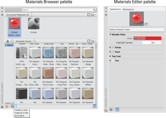
FIGURE 23-11: Adding color and texture to a 3D model with the Materials Browser palette (left) and the Materials Editor palette (right).
Follow these steps to create and manage a new material:
- On the Visualize tab, choose Materials Browser from the Materials panel.
On the Materials Browser palette that opens, click Create a Material (in the lower-left corner) and then choose the material template you want to start with. For example, choose Metallic Paint.
The Materials Editor palette is displayed (see Figure 23-11).
 On the Materials Editor palette, click in the Name field, located below the preview of the material, and enter a name.
Enter new values in the appropriate attributes for the material, and close the palette when you’re done.
The attributes that you can edit vary, based on the type of material template that you choose to start with. When you finish editing the material, you can close or hide the Materials Editor palette. The material is then automatically added to the current drawing.
(Optional) Save the material in a library to use it in more than one drawing. In the Materials Browser palette, at the bottom, click Manage, and then select Create New Library.
The Create Library dialog box is displayed.
- Enter a name and location for the new library. Click Save.
In the Materials Browser palette, drag the custom material that you created onto the name of the new library.
Now you can access the material from any drawing. You can create categories if you want to manage multiple materials within a library. In Materials Browser, right-click the library name, choose Create Category, and then enter a name for the new category. After the category is created, simply select the material from the right side of Materials Browser and drag it to the new category.
You can open Materials Editor directly from the Ribbon by clicking the Materials panel launcher (the little arrow at the right end of the Materials panel label).
Which materials you use in a model depends on what you’re trying to represent. For example, you might choose to make a material semitransparent, to communicate an idea rather than a true material selection. After you create a material, you can apply it to the objects in your 3D model. You can apply materials to objects by
- Layer: Assign materials to all objects on a particular drawing layer. To assign materials by layer, open the Materials slideout on the Render tab and then choose Attach by Layer.
- Object: Assign materials to an object by selecting the object and then, in the Materials Browser palette, right-click the material you want to assign. From the menu that appears, choose Assign to Selection. You can also drag and drop a material from the Materials Browser palette onto an object in a drawing. You can change an object’s Material property by using the Properties palette.
- Face: Assign materials to individual faces of a 3D solid. Select a face using Subobject filtering by holding down the Ctrl key and selecting the face to which you want to apply a material. Right-click the material in the Materials Browser palette, and then choose Assign to Selection from the menu that appears.
Defining a Background
Although your 3D model looks more realistic with some user-defined lighting and custom materials assigned to it, its setting might look a little, well, empty. To fill that empty space beyond the 3D model, you can assign backgrounds to fill your scene. A background is a property of named views, so you set them up in the View Manager dialog box. I cover the View command and View Manager dialog box in Chapter 5.
You can define the background as a solid color, a gradient (two or three colors merging into one another), a raster image like a photograph, or a simulated sky with a sun (this last one is available only with photometric lighting).
Follow these steps to create a new named view and assign a background to it:
 On the Views panel of the Visualize tab, click View Manager.
The View Manager dialog box appears.
Click New to display the New View/Shot Properties dialog box.
For more on creating named views, see Chapter 22.
In the Background area, click the Default drop-down, choose an option to override the default background, and then click OK.
Choose Solid or Gradient if you want a studio-type scene, or choose Image if you have a suitable raster image in which to immerse your model. Any of these options displays the Background dialog box from which you make your settings (see Figure 23-12). Choose Sun & Sky if you want to place your model in the great outdoors. (It’s always fair weather in AutoCAD! Just be aware that sunny, fair days also tend to slow down the program.) Choosing the last option displays the Adjust Sun & Sky Background dialog box, as shown in Figure 23-13.
After the background is defined, select the view from the Views tree and click Set Current.
When View Manager closes, the new background is displayed.
For more information on View Manager, see Chapter 5.
If you don’t want to create a named view first, enter the BACKGROUND command to display the Background dialog box directly.
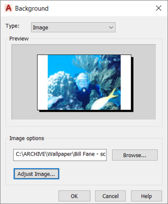
FIGURE 23-12: Painting the canvas of the drawing window.

FIGURE 23-13: Here comes the sun!
Rendering a 3D Model
After you add lights, apply materials, and define a background for your 3D model, you’re ready to press the magic button! Clicking Render tells AutoCAD to round up all the materials and apply them to the objects and faces to which they’re assigned. After materials are assigned, the background is applied to the current viewport, and then, finally, AutoCAD calculates light and shadows based on all those property settings I show you how to make earlier in the chapter.
![]() By default, rendering is performed in the render window, as shown in Figure 23-14. To start rendering your virtual fat into digital lard — how’s that for a grisly image? — click Render to Size on the Visualize tab’s Render panel. And to anyone who says that stuff in Figure 23-14 looks like red paint, not red wine, I would reply “You haven’t tasted my homemade red wine, have you?”
By default, rendering is performed in the render window, as shown in Figure 23-14. To start rendering your virtual fat into digital lard — how’s that for a grisly image? — click Render to Size on the Visualize tab’s Render panel. And to anyone who says that stuff in Figure 23-14 looks like red paint, not red wine, I would reply “You haven’t tasted my homemade red wine, have you?”
To help make rendering as easy as possible, AutoCAD comes with five preset renders. A render preset is a configuration of settings that produce predictable rendering results. The presets range in quality of output, from Draft through Low, Medium, and High to Presentation Quality.
To set a render preset, choose the Render Presets drop-down list on the Render tab’s Render panel. Choose Manage Render Presets at the bottom of the Render Presets drop-down list to open the Render Presets Manager dialog box. Render Presets Manager allows you to create and edit custom render presets. You can start with an existing render preset when you create a custom one.
In addition to rendering a still image with the RENDER or RENDERCROP commands, you can create an animated walk-through of your model by using ANIPATH. To find out more about creating animations, see the AutoCAD online Help system.
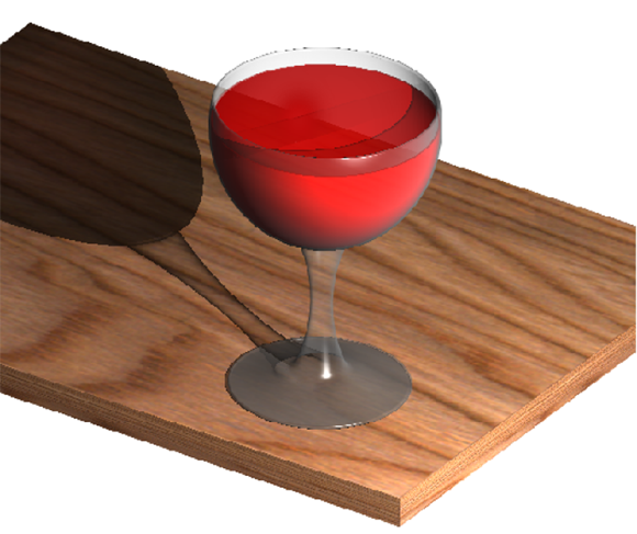
FIGURE 23-14: Rendering a rendering in the render window.