
Presentation patterns are already an old story. Although it is difficult to identify who introduced them, it looks like the seminal programming language SmallTalk dating back to the 1970s is responsible for making one of the first presentation patterns popular; the Model-View-Controller (MVC) design (Kay, 1993; Timms, 2014).
Krasner and Pope (1988) offered a formalized description of the MVC pattern and they basically influenced a generation of programmers who appreciated the merits of keeping apart what appears in the frond-end of an application and what is happening behind the scenes. As the authors state,
“Isolating functional units from each other as much as possible makes it easier for the application designer to understand and modify each particular unit”
—Krasner and Pope (1988)
There are three take-aways from the above statement, first, the separation in the design; then this separation needs be as strong as possible giving independent units and, lastly, the reason for the proposed separation. The developers are able to see clearly what each unit is doing and to alter their behavior.
Keeping functions apart creates an environment where changes to different parts of an application can be performed in a controlled manner, with bugs being spotted and fixed more easily. At the same time, it forces a specific mindset where developers think of applications in a modular way. Put simply, this means that software is developed in units and parts that are linked together with very strict but simple rules to the level of abstraction. This concept is usually described with the term separation of concern (SoC) and it is one of the most important concepts in modern software development and presentation patterns.
Note
A concern in computer science is a group of activities and data that represent different but related functionalities in a piece of software. A separation of concerns (SoC) is a school of thought in which the code is split into several distinct concerns, with minimal overlapping (coupling). If you are not familiar with SoC or you need to refresh your knowledge, visit these general resources (Wikipedia, n.d.; Greer, 2008.) and check this video for a presentation about how SoC fits in object oriented programming and service oriented architectures Lilleaas, 2013).
The benefits you get with such loose connections include the ability to better test, move, and share units among different projects with minimal, if not zero, modifications. Reusability becomes the way to preserve resources (development time and effort) and engineer highly maintainable code.
Three-Tier Application Architecture
Although this breakdown of functionality has been introduced in design patterns, such an approach has been widely used in enterprise applications. It has materialized into what is known as a three-tier architecture. According to this approach, there are three tiers (or layers) in applications:
Presentation layer: The user interface (UI) that shows data to the user and represents states or different forms of data
Business layer: This part deals with data validation and business rules and norms
Data Access layer: A mechanism that connects the application to the medium of choice to store data
It is important to realize that these layers are not just tags we put on sections or files in our application in order to group them together. Earlier we identified that the separation in the design serves different functionalities. Those layers are a way to encapsulate the logic that each part performs. Logic is different from data and data itself is different from information. Data in the form of raw elements (e.g., product price, bank account transactions or discount rate) can move across layers and appear in any of them, and each layer can capture data and interpret it in a way that makes sense to each layer. At this stage, data has been transferred to information. For example, if you consider the discount rate a customer is eligible to enjoy and the price of a product, both pulled from a database, you are just dealing with “data”. Now, if you want to apply the discount to the price of the product the customer ordered, you contextualize that data and generate information.
Both elements (data and information) may appear in any of the aforementioned layers, depending on layer’s functionality (see Figure 1-1). Logic can be seen as the tangible version of information; in this example, the logic would be to multiply the discount rate and the price of the product. Logic can also be seen as the programming code that appears in the layers.

Figure 1-1. Three-tier application structure
Presentation patterns form a different constellation of the tasks performed in an application. They tend to identify a clear front-end that is accessed by a user (the View). Then, the patterns define the part of the application that deals with data, the information (to use the previous term) and programming logic. This part is usually called the Model. A question that arises at this stage is how the communication between the View and the Model is achieved. Many approaches have been proposed and today we have a group of solutions that form the MV* family of patterns.
In the next sections, we are going to visit two of the most prominent members: the Model-View-Controller (MVC) and the Model-View-Presenter (MVP). This book doesn’t discuss those patterns extensively. Instead, it covers the fundamentals before concentrating our attention on the Model-View-ViewModel (MVVM) pattern.
Model-View-Controller (MVC)
The Model-View-Controller (MVC) pattern includes three parts: the Model, the View, and the Controller. The Model represents the state of the application (not only the state of data) and, obviously, sets up and maintains any communication with databases and other sources of data. The View is pretty straightforward. It defines what the user sees and gets from the application. This may include the user interface and different forms of exported data (CSV or HTML files, for example). The Controller receives events from the view and passes them to the Model. The Model processes the events and the View synchronizes itself with any changes that occur in the Model (see Figure 1-2).
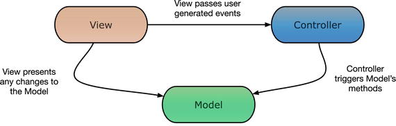
Figure 1-2. The Model-View-Controller (MVC) pattern
Figure 1-2 indicates that the controller is aware of the existence of the Model and, in most cases, of the View, as well. The View is aware of the Controller and the Model. The Model works as a detached and separate entity that exhibits the biggest separation of functionality. A typical problem in the implementation of the MV* patterns is the order of creation of the parts and the responsibility for this. In the most common MVC approach, the Controller is responsible for creating the Model and choosing the View.
Thinking in terms of the three-tier architecture, you may notice that the mapping between the MVC components and those in the three-tier design is not straightforward, as there is an overlap of functions and tasks. Figure 1-3 shows how the two patterns are related.

Figure 1-3. Relationship between the three-tier design and MVC
MVC is widely used to generate rich user interfaces. It is quite popular on the web and the Android operating system implements this pattern (da Silva, 2014). The introduction of the Model as a component with loose connections to the other components implements a clear separation of concerns. Developers can test the View and the Controller as separate entities.
However, the interaction between the View and the Controller and their link to the Model blur the separation among the View, the state of the application, and the state of the View. For example, if you want to change the color of an edit field because the user entered a wrong value, you need to contact the Controller for the user input, observe the Model for the validation, and implement programming logic in the View in order to change the color of the field based on the outcome of the validation. This “state of the view” spans across the different layers of the pattern and it demonstrates that a good level of coupling still exists. This, in turn, introduces a transferability issue. If you want to replace the current View with an alternative one, you need to develop the Controller again (Vice and Siddique, 2012).
Model-View-Presenter (MVP)
The shortcomings of MVC have been addressed by the Model-View-Presenter model. Microsoft has been using this pattern quite extensively in the WPF and Silverlight applications. In this approach, the Controller is replaced with the Presenter and the duties, responsibilities, and capabilities of each part have been altered. There is now a clear separation between the View and the Model and the synchronization is performed by the Presenter (see Figure 1-4).

Figure 1-4. The Model-View-Presenter (MVP) pattern
The View is not aware of the existence of the Model and vice versa. The Presenter has a pivotal role, as it receives user inputs from the View, handles mapping between the View and the Model, and performs complex business logic (Syromiatnikov, 2014). The Presenter is typically created first. Using the previous example with the color of the edit field, the validation is performed in the Presenter and the View is updated using a number of setter methods. The Presenter is now responsible for providing the correct color to the view.
Note
The version of MVP pattern presented here indicates there is no communication between the View and the Model. This is commonly referred as Passive View. There is an alternative implementation of MVP that allows for communication between the View and the Model, but it has limited scope. This is called Supervising Controller. See Martin Fowler’s web site for a detailed presentation of the two implementations (Fowler, 2006a; 2006b).
Figure 1-5 shows the three-tier structure for the MVP pattern.

Figure 1-5. Relationship between the three-tier design and MVP
This time, the Presenter has moved deeper in the business layer. This is because the Presenter is responsible for much of the validation and it keeps most of the state of the View. The Model is unchanged in this version. The three elements are less interlinked and this link is based on more flexible structures (interfaces). This arrangement offers better testability, as the Model and the View can be replaced by mock units or by different implementations.
Apart from these benefits, developers find that while the user interface becomes more sophisticated, there is the need for more code. More code means more opportunities for bugs and an increase in the effort needed to maintain the code base.
Model-View-ViewModel (MVVM)
MVVM came as an alternative to MVC and MVP patterns. SmallTalk introduced this framework in the 1980s, initially under the name Application Model and later using the name Presentation Model (Vice and Siddique, 2012). Most of the arguments that support MVVM are based on the the fact that the View and the View’s state in the previous approaches (MVC/MVP) are still interlinked to the Model to a degree that individual testing is hard to be achieved. This linkage interferes with the general principle of modular programming.
In the MVVM pattern, the ViewModel replaces the Presenter and the Controller. The responsibilities of the ViewModel and the View are now different.
It is common to present the MVVM pattern in a linear way (Figure 1-6). The reason behind this constellation is to emphasize the change to the tasks that are performed from each part of the pattern and to point out the flow of data and information. The Model remains mainly the same as in the MVP design. It is still responsible for accessing different data sources (e.g., databases, files, or servers). Generally, the Model tends to be very thin in the MVVM implementation. The View represents data in the appropriate format (graphical/non-graphical), reflecting the state of the data, and it collects user interaction and events. As with the Model, Views in MVVM include minimum implementation code, only what is required to make the View work and allow user actions.
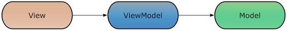
Figure 1-6. The Model-View-ViewModel (MVVM) pattern
In MVVM, the bulk of the code is found in the ViewModel. The concept behind the ViewModel is that this component represents the way the view is expected to be (view state) and is expected to behave to user interactions (view logic). It is the Model of the View in the sense that it describes a set of principles and structures that present specific data as retrieved via the Model. The ViewModel handles the communication between the View and the Model by passing all the necessary data from the View to the Model in a form that the Model can digest. Validation is performed in the ViewModel component.
In this pattern, the components work in sets of two. The View is aware of the ViewModel, updates the ViewModel’s properties, and tracks any changes that occur in the latter. The ViewModel is not aware of the existence of the View. This one-way awareness justifies the linear presentation of the pattern in Figure 1-6, which is also found in many books and articles. In a similar way, the model is not aware of the viewmodel (or the view itself) but it is, only, the viewmodel which has access to the model. The ViewModel passes events and data to the Model, as they are pushed by the view in forms that the Model can interpret. The ViewModel tracks any changes created by the Model and, consequently, pushes to the View any necessary signals according to View and the business rules.
In many articles and presentations of the MVVM pattern, authors often attempt to discuss the one-way relationships between the components by implying that the View and the ViewModel are interchangeable or that they perform equivalent actions. For example, Timms (2014) states that “In MVVM, the view believes that the ViewModel is its view”.
Let me clarify the meaning of this statement, as it can have a number of design implications if it is misinterpreted. As mentioned, the View is aware of the ViewModel but the ViewModel is not aware of the View. If you follow the above statement, the View sees the ViewModel as the tunnel that visualizes or expresses what is taking place in the View. In addition, it indicates that the View can perform filtering or transformations according to the required View logic. This is not the case with the MVVM pattern, because the ViewModel is responsible for the job “behind the scenes of the view”. Moreover, a view can very easily react to, connect to, and visualize several ViewModels, whereas a ViewModel models only one view.
Consider the case of a rowing machine that uses a performance monitor to show various forms of data to the athlete. For the purpose of this example, I used screens from the Concept2 rowing machine (see Figure 1-7).

Figure 1-7. Different screens of the performance monitor of the Concept2 rowing machine (Courtesy of Concept2, Inc; used with permission)
As the athlete pulls the handle, force is transmitted to the internal mechanism of the machine. This mechanism has a circular construction that’s free to rotate around its perpendicular axis. The rowing machine allows the athlete to rotate the internal circular mechanism according to the force and the pace he or she is exercising to the handle. In addition, the machine has an instrument that receives the heartbeats of the athlete. All these technical parts provide the required elements (the variables) to the machine in order to start making calculations, such as elapsed time, consumed calories, speed, etc.
If we attempt to look at the rowing machine under the MVVM paradigm in an educational approach, what the equipment does is to implement the model of the rowing machine (application), which represents a dynamic state of “raw data”. The performance monitor can be considered as a collection of different views of the model. What you need in between is a way to transform data in forms that reveal meaningful information to the athlete. For example, you need to take the rotation speed of the internal mechanism and the elapsed time (as supplied by the model) and translate them to the distance the athletes would cover if they were rowing in a real boat. This transformation of data is the job of the ViewModel in the MVVM domain.
The screen (view) of Concept2 reveals several pieces of information (e.g., elapsed time, strokes per minute, estimated time to cover 500m, distance covered, heartbeats, and projected distance for current speed). Depending on the complexity of the calculations and the connections between them, they can be seen as information provided by different ViewModels. Figure 1-8 shows one possible architecture.

Figure 1-8. A MVVM approach to the performance computer of Concept2 rowing machine
In this design, you have two models (one that deals with data for the physical activity and one that captures the heartbeats of the athlete). These models are used by a number of ViewModels that produce different graphical interpretations (view models) of the data. For example, the second screen has a part that shows the elapsed time and the speed and another part that shows the force curve. What the MVVM approach has done is allow you to understand which part of the application does what and to create loose connections between the processing of data and information and the way they are presented to the users. One point worth noting is that the design shown in the figure is not the only one you can implement. This is one of the strengths of the MVVM approach; it allows you to devise ViewModels that fit your Models and Views instead of having to adjust your Views (and perhaps your Model) to the pattern, as is often the case with the other options in the MV* domain.
In terms of the three-tier architecture, now the Model has been pushed deeper to the data layer, as it mostly deals with data (see Figure 1-9). It still covers aspects of the business layer, as many times transformation of data is required at business level. The View resides in the presentation layer like before and the ViewModel is now charged with a wider range of activities and, therefore, occupies both the presentation and the business layers. The presentation side of the figure captures the fact that the ViewModel implements the logic and state of the View and the business layer corresponds to any logic that allows the manipulation of data in ways that serve the View’s logic.

Figure 1-9. Relationship between the three-tier design and MVVM
Obviously, this is a generalized description of the relationship between the MVVM parts and the three-tier architecture. Different applications, needs, and requirements and different schools of thought in the MVVM universe may position the Model and the ViewModel closer to the business layer, as the discussion about the alternative designs of the Concept2 case has shown.
Summary
This chapter visited the most common design patterns and attempted to create a link to the three-tier architecture design of enterprise software. One of the key points is that MVVM is very flexible and developers can implement it following more than one designs. This flexibility is one of the strong points of the pattern. What follows is an implementation of such a design. The next chapter develops a sample application and the rest of the book shows you how to apply the MVVM paradigm.
References
da Silva, L.P., 2014. “Model-driven GUI generation and navigation for Android BIS apps.” Model-Driven Engineering and Software Development (MODELSWARD), 2014 2nd International Conference on IEEE, pp.400–407.
Fowler, M., 2006a. “Passive View,” available at http://martinfowler.com/eaaDev/PassiveScreen.html [Accessed 29/05/2016].
Fowler, M., 2006b. “MVP: Supervising Controller,” available at http://martinfowler.com/eaaDev/SupervisingPresenter.html [Access 29/05/2016].
Greer, D., 2008. “The Art of Separation of Concerns,” available at http://aspiringcraftsman.com/2008/01/03/art-of-separation-of-concerns/ [Accessed 25/05/2016].
Kay, A.C., 1993. “The Early History of Smalltalk,” ACM SIGPLAN Notices, [online] 28(3), pp.69–95. Available at < https://en.wikipedia.org/wiki/Smalltalk >.
Krasner, G.E. and Pope, S.T., 1988. “A Cookbook for Using the Model-View-Controller User Interface Paradigm”. Journal of Object-Oriented Programming.
Lilleaas, A., 2013. “Service Oriented Architectures (Hardcore Separation of Concerns)”, available at https://vimeo.com/68383348 [Accessed 27/05/2016].
Syromiatnikov, A., 2014. A Journey Through the Land of Model-View-* Design Patterns.
Timms, S., 2014. Mastering JavaScript Design Patterns. Packt Publishing Ltd.
Vice, R. and Siddique, M.S., 2012. MVVM Survival Guide for Enterprise Architecture in Silverlight and WPF. Packt Publishing.
Wikipedia, n.d. “Separation of Concerns”, available at https://en.wikipedia.org/wiki/Separation_of_concerns [Accessed 25/05/2016].