
Serial Peripheral Interface (SPI) is a protocol to be used with certain devices in Johnny-Five and in general, robotics. It came about as a response to typical serial connections (which you don't see often in hobbyist robotics anymore), which were asynchronous in nature. This led to a lot of overhead, so SPI was developed as a way to ensure data was sent and received in a way that was efficient.
In typical serial connections, you have a line from which data goes out (TX) and a line to which the data comes in (RX), and this makes communication difficult. How does the receiver know how fast the sender would be sending bytes, and when are they done sending? This lack of a synchronized time clock is what we mean when we say asynchronous in this context—the sending and receiving devices just send bytes as fast as they please, assuming the receiver will know how to read them.
Let's go through some of the features of SPI:
- SPI uses a separate pin to establish a unified time clock, to sync the receiver and sender. This data clock is flipped between a
HIGHandLOWstate each time a bit is sent—telling the receiver that a new piece of information is being read. - SPI also splits the communications lines into MOSI (Master Out Slave In) and MISO (Master In Slave Out). I'll refer to these by their acronyms, but I will use microcontrollers and devices for our purposes, as in this context they work well.
- The MOSI pin is the line to send data from the microcontroller to the device—output, for our purposes. MISO is a line for the device to send data to the microcontroller—great for sensors and other input needs. Note that if a device does not have any reason to communicate data back to the microcontroller (like our LED matrix), it may leave off the MOSI pin and label the MISO pin something such as "data".
- Finally, SPI devices usually have a CS or SS pin (Chip Select or Slave Select), which is used in setups where multiple devices are used by one microcontroller. This pin is flipped between
HIGHandLOWto let the microcontroller tell the device that it is sending data. You flip the CS pin of the device you are reading from or writing to, and other devices will ignore that data.
So to recap, you need four pins on average—one for the synchronous clock (often labeled SCLK), one for the microcontroller to send data to the device, one for the device to send data to the microcontroller, and one for chip selection.

The SPI explained—Image credit: https://en.wikipedia.org/wiki/Serial_Peripheral_Interface_Bus
Luckily, we don't have to handle timing and bit-shifting ourselves—Johnny-Five gives us a nice API to deal with SPI connections. The functions for these are attached to the Board object and are usually accessed by the component libraries themselves—you won't be using these much unless you're implementing your own SPI device!
This method handles the sending out of data to the device. Also, this is the method used for our LED matrix. The method, Board.shiftOut(dataPin, clockPin, data), shifts out the bytes in data through the pin dataPin using clockPin as a clock.
So considering what we know of SPI, we can determine that Johnny-Five does the following for us:
- Sets the clock, data, and CS pins to the
OUTPUTmode. - Sends startup instructions specific to our device (in the case of our LED matrix, brightness and refresh rate are two examples).
- Waits for data to be sent by our program.
- Sets the CS pin to
LOWto indicate to our device that data is being sent to it. - Writes the data and syncs the clock and data pins for us.
- Sets the CS pin back to
HIGHto indicate we are done sending data.
The benefits of SPI are mainly in the speed and ease-of-use categories; it's way easier to write to and read from SPI devices because they agree on timing and you don't need extra bits or patterns to alert devices of the beginning and end of data.
The downside involves the sheer number of pins required; whereas serial connections only required two pins, SPI requires four, with only one pin that can be shared with multiple SPI devices. Your SPI devices can all share a clock pin, but need their own MISO, MOSI, and CS pins. This can proliferate quite quickly.
Luckily, Johnny-Five has SPI support on quite a few platforms, most notably Arduino microcontrollers. Next, we'll take a look at building a project with an SPI device—our LED matrix!
For our first project, we're going to use an SPI device with our Arduino and Johnny-Five. What we'll use is an LED matrix. This is a matrix of several single-, dual-, or tri-color LEDs that are controlled as a group.
You can really see the benefit of SPI here—controlling each of these LEDs with a pin would require 64 pins for a single-color matrix! For dual- and tri-color, it would be 128 and 192! SPI really gives us a boost here by allowing us to have control based on two pins.
Grab your LED matrix and wire it up! Here's the pin matchup in case you have a different LED matrix: pin 2 runs to DIN or DATA, pin 3 to SCLK, CLK, or clock, and pin 4 to CS, as shown in the following diagram:

Wiring diagram for the LED matrix
Note that the item in the diagram has one extra pin— ignore that! Yours should only have five, and the pins should be clearly labeled on any kit you get.
The LED matrix API in Johnny-Five gives us a lot of ways to play with this output device. Let's take a look at the constructor and a few of the methods, in the following table, before breaking into our code:
There are also functions to draw multiple LEDs at once, but we'll need to talk a bit about how we pass drawing data to the LED matrix first.
As you can see from the preceding .led() function, 1 sets the LED to ON and 0 sets it to OFF. This is a lot like binary, right? That's because it is, and that's how we send all data to the LED matrix—a series of binary bits.
So, for instance, you can send an image to an LED matrix that's 8x8 with an array of rows represented by strings containing binary values for each LED in the row:
var checkerboard = [
  "01010101",
  "10101010",
  "01010101",
  "10101010",
  "01010101",
  "10101010",
  "01010101",
  "10101010"
];
However, this can get unwieldy. You can also send the same data as a set of hexadecimal values representing each row, with two digits in each number; our first row in binary is 0b01010101, which translates to 0x55, and our second row in binary is 10101010, which translates to 0xAA:
var checkerboardHex = [0x55, 0xAA, 0x55, 0xAA, 0x55, 0xAA, 0x55, 0xAA];
Keep these in mind as we talk about the next set of functions, which I call the drawing functions.
Let's explore some of the drawing functions in the following table:
So, .row() and .column() work with one hexadecimal value—.row(0, 0xFF) sets the first row of LEDs to ON for all matrices.
.draw can accept a few things as a valid input. We have shown many of these in previous examples: Strings of binary characters and hexadecimal values, both in an array of rows. But luckily, the library already has several characters implemented for us. The predefined characters for LED matrices in Johnny-Five are as follows:
- 0 1 2 3 4 5 6 7 8 9…
- ! " # $ % & ' ( ) * + , - . / : ; < = > ? @
- A B C D E F G H I J K L M N O P Q R S T U V W X Y Z [ ] ^ _ `
- a b c d e f g h i j k l m n o p q r s t u v w x y z { | } ~
You can pass in a string containing one of these characters as your value, as shown here:
myMatrix.draw('~'),
myMatrix.draw('A'),
This allows us much more easily to show text and numerical output on our LED matrix.
Now that we've explored the API, let's write some code that loads a character that we define, then injects our matrix and another character that we define into the REPL so we can play with it live!
Place the following into led-matrix.js:
var five = require("johnny-five");
var board = new five.Board();

board.on("ready", function() {

  // our first defined character-- using string maps
  var checkerboard1 = [
    "01010101",
    "10101010",
    "01010101",
    "10101010",
    "01010101",
    "10101010",
    "01010101",
    "10101010"
  ];

  //our second defined character-- using hex values
  var checkerboard2 = [ 0xAA, 0x55, 0xAA, 0x55, 0xAA, 0x55, 0xAA, 0x55];

  var matrix = new five.Led.Matrix({
  pins: {
  data: 2,
  clock: 3,
  cs: 4
    }
  });

  matrix.on();
  matrix.draw(checkerboard1); //draw our first character

  this.repl.inject({
    matrix: matrix,
    check1: checkerboard1,
    check2: checkerboard2
  });
});
Once you've got the code in, run it with the following:
node led-matrix.js
In a few seconds, your LED matrix should light up with a checkerboard pattern like the following:
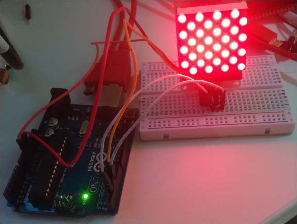
A matrix example with checkbox character
Now's the time to play with the REPL—for instance, try the following command line:
matrix.draw(check2);
And watch it change! You can also clear the matrix with the following command line:
matrix.clear()
Draw a predefined character with the following command line:
matrix.draw('J'),
After clearing again, try the .led and .row functions as follows:
matrix.clear();
matrix.led(3, 3, 1)
matrix.row(1, 0xA1);
You now have a good grasp of the LED matrix and using SPI devices with Johnny-Five! We've discussed the upsides and downsides of SPI communications and covered a little about why serial connections remove and create a lot of overhead. Now, we're going to take a look at I2C—a protocol designed to gather many of the benefits of SPI and serial and join them together.