7
Data Hiding in the Encrypted Domain
Pauline PUTEAUX and William PUECH
LIRMM, Université de Montpellier, CNRS, France
In recent years, the development of cloud computing has meant that more and more users are uploading their personal data to remote servers. However, this can result in major security breaches that pose a constant risk in terms of confidentiality, authentication and integrity. To mitigate these problems, multimedia data may be encrypted prior to transmission and storage. In this chapter, we focus on the problem of processing this encrypted multimedia data, specifically on data hiding in the encrypted domain.
7.1. Introduction: processing multimedia data in the encrypted domain
For security reasons, more and more digital data are encrypted before being transferred or archived. During the transmission or archiving process, these data often need to be analyzed or processed directly in the encrypted domain, without knowing its original, clear content (Erkin et al. 2007). Figure 7.1 shows some of the main applications for multimedia data processing in the encrypted domain: sharing visual secrecy between multiple people; data hiding in encrypted multimedia data (so that the person inserting or extracting data does not have access to its original content); recompression of crypto-compressed images or videos (for secure transmission over low-speed networks); indexing and searching for multimedia content in encrypted databases; and the correction of noisy encrypted images. Note that the processing of encrypted multimedia data in the context of homomorphic encryption is discussed in Chapter 6, and, as such, these specific applications will not be presented again here.

Figure 7.1. Target applications for multimedia data processing in the encrypted domain: a) visual secret sharing; b) recompression of crypto-compressed images; c) correction of noisy encrypted images; d) searching and indexing in encrypted databases; and e) data hiding in the encrypted domain
In this section, we describe three of these applications: visual secret sharing (section 7.1.1), indexing and searching for multimedia content in encrypted databases (section 7.1.2) and data hiding in the encrypted domain (section 7.1.3).
The recompression of crypto-compressed images is discussed in detail in Chapter 4, and the notion of visual secret sharing is covered in Chapter 8.
7.1.1. Applications: visual secret sharing
There are two categories of methods that may be used to share visual secrets: visual cryptography, as proposed by Naor and Shamir (1994), and secret image sharing, as proposed by Thien and Lin (2002). Visual cryptography consists of sharing visual information (text or image) between several individuals in a secure manner. In the approach described in Naor and Shamir (1994), developed for binary images, two images known as shares are generated after sharing. In these images, the black pixels of the secret image are protected, while the white pixels are randomized. The secret image is then reconstructed using an exclusive-or between the two shares. Secret image sharing draws on secret sharing methods developed independently by both Blakley (1979) and Shamir (1979). The method, broadly based on the concept of polynomial interpolation, enables an image to be shared between n users in a secure manner (Thien and Lin 2002). Each user receives a personal share in the form of an image. This share is unique and in visual terms appears to have been generated randomly. The original image can only be reconstructed by assembling at least k shares, with k ≤ n. Thus, with k − 1 shares, no information can be retrieved concerning the original content of the image. The parameter k may be higher or lower depending on the level of trust within the sharing group. Note that the reconstructed secret image I′ is very similar to the original secret image I, and may even be strictly identical when using a “perfect” method. Figure 7.2 shows an illustration of the secret sharing process.

Figure 7.2. Illustration of the secret image sharing process
7.1.2. Applications: searching and indexing in encrypted image databases
Searchable encryption allows a database to be stored in a secure manner on an unreliable server while maintaining content search and indexing functionalities. With the development of cloud computing, efficient searchable encryption approaches are now of crucial importance. The methods used must ensure that the stored data are secure without increasing their size. Furthermore, the computational cost of search and indexing operations must be low. While most existing methods have been developed for textual document retrieval, image retrieval methods based on content analysis are also valuable for many applications. In the medical field, for example, doctors may use these techniques to match medical images of patients with similar symptoms to help establish a diagnosis (Pavlopoulou et al. 2003). Law enforcement agencies may also use these approaches to compare evidence from crime scenes with records in their archives (Jain et al. 2009). Lu et al. (2009a) were the first to propose a search system for images in the encrypted domain based on content analysis, preserving the visual privacy of the original images. Their approach used the reverse index and the secure min-Hash. Elsewhere, the same authors presented a study of three different techniques for protecting the features of an image: randomizing, projection and random encoding of their bitplanes (Lu et al. 2009b). They showed that features encrypted by bitplane randomization or by random coding can be used to compute a Hamming distance in the encrypted domain. Furthermore, features encrypted by bitplane randomization can be used to compute an L1 distance in the encrypted domain. Hsu et al. (2012) proposed a method based on homomorphic encryption, where the use of the Scale-Invariant Feature Transform (SIFT) to extract features from the image does not compromise the confidentiality of the original content. Ferreira et al. (2015) described a new image encryption method that permits retrieval in the encrypted domain. In this case, texture and color information are separated then encrypted independently. Texture information is encrypted using a probabilistic cryptosystem to protect the image content, while color information is encrypted by a deterministic cryptosystem to enable searching based on color characteristics. Finally, Xia et al. (2016) recently found that none of the state-of-the-art methods took account of the idea that users could perform dishonest searches and illegally distribute the retrieved images. The authors proposed a solution to this problem using a protocol based on data hiding.
7.1.3. Applications: data hiding in the encrypted domain
Methods for data hiding in the encrypted domain are used to conceal secret messages in the encrypted domain without access to the key used to encrypt multimedia data, or to the original clear content. These approaches are mostly used to annotate multimedia data, or for authentication purposes. The secret message that is inserted can thus be a label, timestamp data, or information about the origin of the data, such as EXIF data for images. In this type of approach, the owner of the multimedia data and the person inserting the secret message may be different people. For example, if images are stored on a cloud platform, encryption is performed by the image owner to protect the original content, and then the resulting encrypted image is stored on the cloud server. The server manager has no access to the original content of the image. However, they can still insert a secret message directly in the encrypted domain. In this particular application, the labels inserted into encrypted images may permit better management of the cloud server by administrators (Qian et al. 2018). During the decryption phase, the secret message should be extracted without error. In addition, if an authorized user downloads the marked encrypted image from the cloud server, they should be able to retrieve the original image content without loss after the decryption operation. Data hiding methods thus provide an alternative to traditional file management systems, providing additional information inside the encrypted multimedia data itself, instead of using an auxiliary metadata file. To this end, many methods have been proposed since 2008, aiming to achieve the best trade-off between the payload (i.e. the amount of data embedded), the bit error rate in the secret message and the quality of the reconstructed media data compared to the expected original data.
In the remainder of this chapter, we focus on data hiding (DH) methods in the encrypted domain. Section 7.2 presents the main aims of DH methods. Section 7.3 provides a more detailed description of different classes and characteristics. The main state-of-the-art methods are described in section 7.4 and compared in section 7.5. In section 7.6, we describe a high-capacity DH method based on MSB prediction, which achieves very good results. We conclude our discussion in section 7.7.
7.2. Main aims
Data hiding is an approach used to conceal secret data inside a signal (such as an image). After extracting these data, it must be possible to reconstruct the original image without alteration. Furthermore, for confidentiality reasons, it may be necessary to make an image illegible using encryption methods. Encryption and data hiding can be carried out simultaneously. Puech et al. (2008) described one of the very first methods for data hiding in the encrypted domain in 2008. Several different methods have since been developed. As can be seen from Figure 7.3, there were 40 times more publications on this subject in 2019 than in 2009. Target applications for hiding data in the encrypted domain include digital rights management (buyer–vendor protocol), cloud storage, patient confidentiality (medical field), classified data management (military), journalism, video surveillance and data analysis.

Figure 7.3. Evolution of publications on data hiding in the encrypted domain (2008–2019)
7.2.1. Digital rights management
Before selling multimedia data, distributors encrypt these data to ensure its visual privacy. Furthermore, to prevent illegal distribution, the distributor watermarks the data with information about the buyer. When media data are purchased, each copy sold is therefore unique. This is particularly useful for tracking and tracing purposes, making it possible to identify a customer when a suspicious copy is found.
However, since the distributor knows the watermark, dishonest clients may claim that illegal copies are in fact being distributed by the distributor. Conversely, it is also possible for the distributor to “frame” an honest customer as dishonest by inserting their personal watermark into the media data and distributing copies. Solutions have been proposed to prevent this based on ensuring that the distributor does not know the final form of the watermark (Poh 2009).
7.2.2. Cloud storage
Users may encrypt personal multimedia data before storing it on a cloud platform in order to preserve their privacy. To facilitate server management, the cloud platform administrator embeds data required for indexing purposes, for example, directly into the encrypted domain (Qian et al. 2014).
7.2.3. Preserving patient confidentiality
In hospitals, medical images of patients are encrypted to preserve their privacy (Bouslimi et al. 2012). In addition, patient information is embedded into the resulting encrypted images for ease of identification. A nurse or administrative worker handling the data may extract this information without viewing the original. Authorized physicians, on the other hand, may access both the patient’s identification information and the clear images.
7.2.4. Classified data
In the military field, low-ranking officers (e.g. a lieutenant) may extract the label inserted into encrypted multimedia data for administrative purposes (e.g. copying, archiving or transferring) without being able to access the original content. A higher ranking officer (such as a general) may be able to decrypt the data, giving them access to both the inserted label and the original clear data (Cao et al. 2016).
7.2.5. Journalism
Journalists may encrypt multimedia data before sending it to the company for which they are working, so that only authorized persons may access the content. This guarantees exclusive coverage of an incident or event, preventing competitors from accessing the information. Details such as the sender’s identity or the GPS coordinates of a field report may be inserted for authentication purposes (Wong and Tanaka 2014) to prevent content counterfeiting.
7.2.6. Video surveillance
Video recordings from surveillance cameras are selectively encrypted (masking regions of interest, such as faces, for example) to protect people’s privacy (Dufaux and Ebrahimi 2008). Information concerning image acquisition (camera ID, time and date) must be included in the recorded images for authentication purposes, notably if the video stream is used as proof in a legal context.
7.2.7. Data analysis
Huge amounts of data are now generated and collected every day (Hey et al. 2009). These data must be labeled, but also remain confidential.
7.3. Classes and characteristics
As we saw in section 7.2, many data hiding methods have been developed for digital images in recent years. Several different classes and characteristics can be defined. We shall begin by defining different properties used to categorize the state-of-the-art methods in section 7.3.1. In section 7.3.2, we shall describe classic approaches to image encryption in data hiding methods. Finally, in section 7.3.3, we detail the criteria used to evaluate the performance of these methods.
7.3.1. Properties
In this section, we describe the properties that define and categorize data hiding methods, namely the trade-off between embedding capacity and the quality of the reconstructed image, and approaches that can be used for the encoding and decoding phases.
7.3.1.1. Capacity/quality trade-off
In data hiding methods, there is a real trade-off between the number of secret bits inserted in the encrypted image and the quality of the reconstructed image obtained after decrypting the marked encrypted image. A distinction may be made between two types of methods, depending on the quantity of bits of a secret message that can be inserted. Data hiding methods with a payload of less than half a bit per pixel are said to be low capacity. Conversely, a method is said to be high capacity when the payload is close to or in excess of one bit per pixel. No state-of-the-art methods offered the capacity to insert more than one bit per pixel until 2018. Some methods allow the message to be kept secret when the clear image is decrypted: in these cases, it is essential for the reconstructed image to be similar to the original clear image. A method is said to be fully reversible when the original image can be reconstructed without loss after the message has been extracted. Finally, note that the higher the number of bits to insert in the secret message, the more likely it is that the reconstructed image produced during the decoding phase will be degraded.

Figure 7.4. Two possible encoding approaches: a) reserving room before encryption (RRBE) or b) vacating room after encryption (VRAE)
7.3.1.2. Two approaches to encoding
In terms of encoding approaches, data hiding methods may be grouped into two categories: those in which space is freed up for message embedding before encryption (reserving room before encryption, RRBE) and those in which space is made available for the message after encryption (vacating room after encryption, VRAE). These two approaches are shown in Figure 7.4. In RRBE methods, the original image is pre-processed by the owner before encryption in order to leave space for the bits of a secret message. The image is then encrypted and another person – such as a cloud server manager – may insert the bits of a secret message into the specific positions reserved for this purpose (Ma et al. 2013; Cao et al. 2016; Zhang et al. 2016; Puteaux and Puech 2018a). In VRAE methods, the content of the original image is directly encrypted by the owner with no pre-processing. The cloud server manager then modifies the encrypted data in order to embed the bits of the secret message (Puech et al. 2008; Hong et al. 2012; Zhang 2011, 2012; Qian et al. 2014). Both approaches are effective, but both present certain drawbacks. RRBE methods allow a larger number of bits to be embedded but require pre-processing before encryption. This may be difficult in practice if the owner of the image is not aware that the encrypted image needs to be analyzed or processed at a later stage. In VRAE methods, the person receiving the marked encrypted image must be able to predict the contents of the original image in order to reconstruct it. This means that the retrieved image is generally an estimation of the original, and perfect reversibility is not possible. Furthermore, the number of secret bits embedded must remain low in order to minimize distortion.
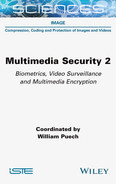
7.3.1.3. Two approaches to decryption
The extraction of a secret message and the reconstruction of the original image may be carried out jointly or separately during the decryption phase, as shown in Figure 7.5. In the joint case, the clear image cannot be obtained without knowing the data hiding key. Using the encryption key alone, it is only possible to obtain a degraded version of the original image (Puech et al. 2008). Furthermore, in certain methods, knowledge of the data hiding key alone is not sufficient to extract the message (Zhang 2011). In the case of separate operations, the message can be extracted and the original image can be reconstructed separately, i.e. by two different people. If a user only knows the encryption key, two cases are possible:
- – a clear image, marked with the secret message but very similar to the original, may be obtained (Zhang 2012);
- – the original image may be reconstructed perfectly, without being marked by the secret message (Puteaux and Puech 2018a).
Using the data hiding key alone, users may extract the secret message directly from the encrypted image. Note that the message can also be extracted in the clear domain if the chosen method allows this message to be preserved within the clear image.
7.3.2. Classic approaches to encryption
Stream-based encryption methods are generally used to preserve the confidentiality of original data in data hiding methods; however, in some cases, block encryption may be used, for example using the AES algorithm (Daemen and Rijmen 1999), or a public key cryptosystem such as Paillier’s approach may be preferred (Paillier 1999).
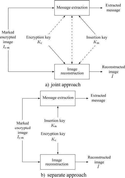
Figure 7.5. Two possible decryption approaches. The embedded data are extracted and the original image is reconstructed: a) jointly and b) separately
7.3.2.1. Stream encryption
In most state-of-the-art methods (Zhang 2011), the original image I is stream encrypted. As we see from Figure 7.6, an encryption key Ke is used as the seed for a pseudo-random number generator (PRNG). This PRNG is used to obtain a sequence of pseudo-random bytes s(i, j). The encrypted pixels pe(i, j) are then calculated using an exclusive-or with the values of s(i, j):
As the encryption operation is fully reversible and causes no overflow, the original image I can be retrieved from the encrypted image Ie with no alterations. Note that the pseudo-random sequence may be generated using a cryptographically secure pseudo-random number generator (CSPRNG), a chaotic generator (Li et al. 2005), or even the AES algorithm (Daemen and Rijmen 1999) in OFB mode.

Figure 7.6. Stream encryption
7.3.2.2. Symmetrical block encryption
Certain methods in the state of the art exploit the correlation within the pixel blocks of images in the clear domain (Puech et al. 2008). They thus use symmetrical block encryption to preserve the block structure of pixels in the encrypted image. The most commonly used method is the Advanced Encryption Standard (AES) (Daemen and Rijmen 1999). Designed in 1999 by Joan Daemen and Vincent Rijmen, AES is composed of a set of operations, repeated over several repetition cycles, or rounds. The number of rounds depends on the size of the encryption key: 10 cycles for 128-bit keys, 12 cycles for 192-bit keys or 14 cycles for 256-bit keys. The first stage in encrypting a 128-bit sequence is to apply the AddRoundKey operation. Each byte in the sequence is combined with an associated block in the round key using an exclusive-or operation. Next, four different operations are performed during each round: SubBytes, ShiftRows, MixColumns and AddRoundKey. The SubBytes operation is a nonlinear substitution step where each byte is substituted with another according to a conventionally defined table. The ShiftRows operation is a transposition step where the last three lines of the block undergo a cyclical shift. MixColumns is a linear shuffle operation that operates on the columns of the block, combining the four bytes of each column. The last round consists of the same operations with the exception of MixColumns. The AES algorithm has the capacity to support different encryption modes, such as ECB (Electronic Code Book), CBC (Cipher Block Chaining), CFB (Cipher Feedback), OFB (Output Feedback) or CTR (Counter), for example.
7.3.2.3. Public key encryption
Many data hiding methods that draw on the probabilistic and homomorphic properties of public key cryptosystems use Paillier’s cryptosystem to encrypt the original image. Paillier’s system, introduced in 1999 (Paillier 1999), involves the following steps. First, to generate the public and private keys, two prime numbers p and q are chosen such that:
Values n and λ are then calculated:
A number ![]() is selected such that:
is selected such that:
where L(·) is the application defined by:
The public key is thus (n, g) and the private key is (λ, μ). Given a message to encrypt m, with 0 ≤ m < n, in the case of image encryption, m generally corresponds to a pixel block. To encrypt this message, a random number r is generated, with r ∈ ![]() . Note that choosing r in this way guarantees that the Paillier cryptosystem will be non-deterministic.
. Note that choosing r in this way guarantees that the Paillier cryptosystem will be non-deterministic.
The final step is to calculate the encrypted message c:
where E(·) is the encryption function of the Paillier ecosystem.
Note here that squaring n results in an inflation of the size of the encrypted message in relation to the clear message.
The original clear message m can then be reconstructed from the encrypted message c:
where D(·) is the encryption function of the Paillier cryptosystem.
Furthermore, Paillier’s cryptosystem possesses a homomorphic property in that decrypting the product of two encrypted messages corresponds to summing the two corresponding messages m1 and m2 in the clear domain:
7.3.3. Evaluation criteria
Data hiding methods are evaluated based on the quantity of bits embedded in terms of payload, the bit error rate during message extraction, and the visual quality after reconstruction compared to the original clear image. In addition, the visual security level of the marked encrypted image can also be assessed by in-depth statistical analysis.
7.3.3.1. Quantity of embedded bits
The quantity of bits embedded in a message is expressed in bits per pixel. For an image with pixels encoded over 256 levels of gray, this quantity is thus between 0 and 8 bpp. A distinction can be made between embedding capacity and payload. Embedding capacity relates to the total number of bits that can be inserted into an image by applying the data hiding method. The payload denotes the total number of bits in a message that can be inserted into the image. Thus, the payload may be significantly lower than the embedding capacity, notably when the chosen data hiding method requires some of the capacity to be sacrificed to leave space for additional information, for example for overflow management (Huang et al. 2016) or for pixels that are hard to predict (Puteaux and Puech 2018a).
7.3.3.2. Bit error rate
When extracting the message from the marked encrypted image (or the marked decrypted image, where applicable), the bit error rate is calculated by dividing the number of erroneously reconstructed bits by the total number of bits in the secret message. The resulting number of bits must be as low as possible to ensure proper transmission of the secret data inserted into the encrypted image. In most of the state-of-the-art methods, the bit error rate is zero, indicating that the secret message is extracted without error.
7.3.3.3. Visual quality
The visual quality of the image that is reconstructed by decrypting the marked encrypted image compared to the original clear image can be evaluated using two different metrics, both widely used in image coding and compression. Note that the quality of the reconstructed image can be evaluated both before and after message extraction. If the chosen data hiding method allows the secret message to be retained in the decoded image, we may evaluate the distortion resulting from message insertion in the original image. However, it is important to realize that some methods are irreversible, and the original image cannot be recovered without alteration after the message has been extracted.
7.3.3.3.1. Peak signal-to-noise ratio
Peak signal-to-noise ratio (PSNR) is used to measure the quality of a reconstructed image with respect to the original image. The following formula is used:
where ![]() is a pixel in the original image and p′(i, j) is the corresponding pixel in the reconstructed image, both of size m × n pixels coded on 255 levels of gray.
is a pixel in the original image and p′(i, j) is the corresponding pixel in the reconstructed image, both of size m × n pixels coded on 255 levels of gray.
PSNR is measured in decibels (dB). The PSNR between two images with entirely different content is around 10 dB. For two images which are similar but affected by noise, it is around 15 dB. If the two images are very similar, the value is above 30 dB. Finally, in cases of perfect reconstruction, that is, when the two images are strictly identical, the value of the PSNR tends toward ![]() Note that many data hiding methods that are considered reversible have a PSNR value of around 50 dB. The major drawback of PSNR is that it fails to take account of the visual quality of the reconstructed image; as such, it cannot be considered to be fully objective. For this reason, another metric – structural similarity (SSIM) – is also used.
Note that many data hiding methods that are considered reversible have a PSNR value of around 50 dB. The major drawback of PSNR is that it fails to take account of the visual quality of the reconstructed image; as such, it cannot be considered to be fully objective. For this reason, another metric – structural similarity (SSIM) – is also used.
7.3.3.3.2. Structural similarity
SSIM is used to evaluate the similarity between the structures of two images, rather than between corresponding pixels, as in the case of PSNR (Wang et al. 2004). The underlying hypothesis is that the human visual system is more sensitive to changes in the structure of an image. The formula used is as follows:

where x and y are windows in the two images, E(x) is the mean of the set x, V (x) is its variance, Cov(x, y) is the covariance between sets x and y, γ1 = (0.01 × 255)2 and γ2 = (0.03 × 255)2.
This formula is applied to different windows in the two images to be compared. The average between the different values obtained is then calculated to obtain the global SSIM value. This value is between 0 and 1; a value of 1 indicates that the two images are strictly identical. Note that it is often necessary to observe at least three decimal places for the SSIM value to be significant.
7.3.3.4. Visual security level
No metric has yet been defined specifically to evaluate the visual security level of marked encrypted images. As such, we shall draw on the work of Preishuber et al. (2018) to describe the metrics used by many authors to experimentally demonstrate the visual security of image encryption methods. We conclude that a good level of visual security is achieved in the marked encrypted image when the message embedding phase does not affect the security level of the encryption method. On the other hand, if the embedded message is itself encrypted, embedding this message into an encrypted image amounts to hiding “noise in noise”; thus, the encrypted message cannot, a priori, be detected in the encrypted domain.
7.3.3.4.1. Correlation coefficient
One classic approach is to observe the correlation between pixels in horizontal, vertical and diagonal directions. M pairs of neighboring pixels (xi, yi) are chosen in all three directions, with xi ∈ x and yi ∈ y, in order to calculate the correlation coefficient:

where E(x) is the mean of set x.
The value of this correlation coefficient falls between – 1 and 1, with – 1 and 1 indicating strong correlation and 0 an absence of correlation. As the values of neighboring pixels in the clear domain are strongly correlated, corrx, y is generally high for the original image. However, it should be close to zero in the encrypted domain.
7.3.3.4.2. Shannon entropy
Shannon entropy is a measure of the quantity of information used to evaluate the randomness of the distribution of pixels in a marked encrypted image (Shannon 1948):

where I is an image of m × n pixels coded on N values ![]() is the probability associated with αk.
is the probability associated with αk.
The entropy value is expressed in bits per pixel (bpp) and falls between 0 bpp and log2(N) bpp, when the pixel distribution is perfectly uniform. Generally speaking, grayscale images are coded on 256 values. In this case, the maximum entropy is log2(256) = 8 bpp. The entropy value of a marked encrypted image should be very close to the maximum entropy value.
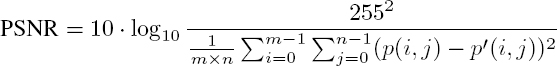
7.3.3.4.3. χ2 test
The uniformity of the pixel distribution in a marked encrypted image can also be evaluated using the chi-square test, defined as:
where the pixels in the image are coded on N values ![]() is the probability associated with αk.
is the probability associated with αk.
The lower the value obtained, the closer the pixel distribution of the marked encrypted image is to a uniform distribution, indicating a higher level of visual security. Note that the square root of the χ2 value is often used.
7.3.3.4.4. Number of changing pixel rate
The number of changing pixel rate (NPCR) between two images of size m × n pixels, p(i, j) and ![]() is given by Wu et al. (2011):
is given by Wu et al. (2011):

where d(i, j) is defined by:

This value is expressed in % and is used to determine the extent to which an encrypted (or marked encrypted) image differs from the original. Thus, the closer the value is to 100%, the larger the difference between the two images, and the higher the level of visual security.
7.3.3.4.5. Unified averaged changed intensity
Unified averaged changed intensity (UACI) is also used to measure the difference between two images of m × n pixels, of which pixels p(i, j) and ![]() are coded on 256 grayscale values (Wu et al. 2011):
are coded on 256 grayscale values (Wu et al. 2011):
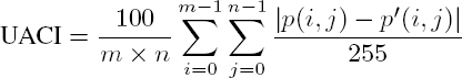
This value is also expressed as a percentage. The higher the value, the higher the visual security level. Note that the ideal value depends on the range of tones used in the image. This metric can be used to test the sensitivity of the encryption key. The original image is encrypted using two keys with only one different bit, and the resulting images are then compared. In this case, the optimum value of the UACI is 33.33% (Preishuber et al. 2018). However, the UACI value is often lower when used to compare an original clear image and its marked encrypted counterpart. Note that there is no statistical decision criterion for this test; optimal values are determined on a purely experimental basis.
7.4. Principal methods
In this section, we shall describe data hiding methods that we consider to be particularly representative of the current state of the art. These are grouped according to key concepts: image partitioning (section 7.4.1), histogram shifting (section 7.4.2), encoding (section 7.4.3), prediction (section 7.4.4) or public key encryption (section 7.4.5). The criteria and characteristics defined in section 7.3 will also be discussed.
7.4.1. Image partitioning
In several data hiding methods, the pixels in an image are divided into two groups. Those in the first group are used to embed a secret message, while those in the second group are not marked and are used to reconstruct the original, clear image. Partitioning can be performed before or after encryption, depending on the chosen methods. Some authors have applied this partition in a pseudo-random way by using the data hiding key (Zhang 2011); more sophisticated techniques rely on an analysis of the properties of the clear pixels (Ma et al. 2013).
7.4.1.1. Use of the data hiding key
In one of the very first data hiding methods, Zhang (2011) proposed a stream-based approach to encrypting the original image. The encrypted image is then divided into blocks of s × s pixels, with the aim of hiding one bit of the secret message in each block. The pixels in each block are then partitioned into two groups, S0 and S1, using the data hiding key. If the bit of the secret message to be inserted is 0 (respectively, 1), the three least significant bits (LSB) of each pixel in S0 (respectively, S1) are inverted. During the decoding phase, the marked encrypted image is decrypted in order to obtain an approximation of the original image. The five most significant bit (MSB) planes are perfectly reconstructed, and only the LSB may be altered. A fluctuation function is then used to evaluate the irregularities in the S0 and S1 groups of reconstructed pixels. The bits of the secret message can then be extracted and the original configuration of each block can be recovered. However, while the chances of perfectly reconstructing the original image can be improved by increasing the size of the blocks, Zhang’s method is not reversible as perfect reconstruction is not guaranteed. Moreover, the payload is low (less than 0.1 bpp) since only one bit is inserted per block. Improvements to this method have been proposed in the literature (Zhang 2011; Hong et al. 2012).
7.4.1.2. Use of a fluctuation function
Ma et al. (2013) were the first to propose a RRBE approach, in a radical break from existing methods. The authors began by dividing the original image into blocks. The correlation between pixels in each block was evaluated using a fluctuation function. The blocks were then partitioned into two groups, A and B: A is composed of textured blocks and B of relatively homogeneous blocks. Blocks from group A are placed at the beginning of the image and blocks from group B are placed at the end. To free up space for a secret message, the bits of the LSB planes of A are inserted, by histogram shifting, into the clear domain in the group B pixels. The resulting image is then stream-encrypted and the number of pixels that can be marked is stored in the LSB of the first pixels of A. Using this information, a secret message can be embedded by simply substituting the LSBs of the other pixels of A. Note that the first three LSB planes of each pixel can be used. The total payload of the marked encrypted image can thus reach 0.5 bpp: a payload 10 times higher than that offered by previous state-of-the-art methods. Finally, in the reconstruction phase, message extraction and original image reconstruction can be performed separately.
7.4.2. Histogram shifting
Histogram shifting techniques have been used in many data hiding methods, due to their simplicity and capacity to produce very high quality images after decrypting the marked encrypted image. Clear, natural images present high levels of correlation between neighboring pixels. Thus, the distribution of differences between pixels is modeled by a Laplacian centered about zero. This statistical data can then be used to embed data using histogram shifting methods (Huang et al. 2016; Xiao et al. 2017; Ge et al. 2019).
7.4.2.1. Pixel difference or prediction error histograms
Huang et al. (2016) noted that existing data hiding algorithms designed for the clear domain cannot be applied in the encrypted domain. This is due to the fact that classical encryption methods are unable to maintain the correlation between neighboring pixels without creating a security risk. The authors thus developed a new strategy for image encryption that is robust with respect to the application of classic data hiding methods in the clear domain. First, the original image is divided into non-overlapping blocks. All pixels in each block are encrypted by applying an exclusive-or with the same pseudo-randomly generated byte. Next, the blocks in the resulting image are pseudo-randomly swapped. Note that pixels within the same block are not swapped: only the order of the blocks changes. Using this encryption method, the statistical properties of the clear image, notably pixel difference or prediction error histograms, are preserved. This means that existing data hiding algorithms designed for the clear domain can now be applied directly in the encrypted domain. However, embedding capacity is limited by the need to manage overflow problems.
7.4.2.2. Homomorphism and pixel value ordering
Xiao et al. (2017) proposed an adaptation of the pixel value ordering concept, defined for the clear domain by Li et al. (2013), for the homomorphic encrypted domain. The authors began by noting that, by adapting the encryption method, it was possible to obtain a histogram of pixel differences with a zero-centered Laplacian distribution, identical to that of the clear domain, in the encrypted domain. After encryption, the image is divided into non-overlapping blocks of 2 × 2 pixels. The four pixels in each block are then rearranged into ascending order, noted ![]() The pixel with the highest value (pe4) is then selected for data hiding. This operation is carried out by calculating the difference d between pe4 and pe3. A bit b ∈ {0, 1} is then inserted into pe4 as a function of the value of d, resulting in a marked version pe−m4 such that:
The pixel with the highest value (pe4) is then selected for data hiding. This operation is carried out by calculating the difference d between pe4 and pe3. A bit b ∈ {0, 1} is then inserted into pe4 as a function of the value of d, resulting in a marked version pe−m4 such that:

Note that a similar operation can also be applied to embed a bit in the pixel with the lowest value pe1. In this method, the order of the pixels remains unchanged after the data hiding. In terms of the histogram, this operation is equivalent to expanding the bins associated with the difference values of 0 and 1, and shifting the other bins. This method offers a solution to the data expansion problem encountered with many similar methods in the encrypted domain. Nevertheless, the embedding capacity is limited: 0.2 bpp. This is due to the fact that the marked encrypted image needs to store a location map of blocks that are prone to overflow, resulting in a significant payload reduction.
7.4.2.3. Pixel value histogram
Ge et al. (2019) recently proposed a data hiding method based on a shift in the pixel value histogram. Instead of using the pixel difference or prediction error histogram, as in Huang et al. (2016), the authors suggest modifying pixel values directly within a block. Unlike Xiao et al. (2017), the pixels used for data hiding are not necessarily those with the highest, or lowest, value in the block. Two reference pixels, pei and pej , with pei < pej , are selected in a pseudo-random manner using a data hiding key. All other pixels pek in the block are then modified to pe−mk in order to embed a bit b of the secret message:

This operation is applied to all blocks in the image. Furthermore, secret data can be embedded several times throughout the image: this has the effect of increasing the embedding capacity. With a single pass over the image, the Ge et al. (2019) method embeds half of the payload obtained in the Xiao et al. (2017) approach, since the size of the location map for blocks subject to overflow problems is larger. If several passes are performed, on the other hand, a payload of 0.8 bpp can be reached if a degradation in the quality of the original image is acceptable.
7.4.3. Encoding
Some of the methods in the state of the art apply encoding to the image data – before or after encryption – in order to optimize the number of bits needed to represent these data. This compression phase vacates memory space that can then be used to embed bits of a secret message. There are many available algorithms that can be used for this encoding. The Qian and Zhang (2016) method, based on distributed source coding, and the Cao et al. (2016) method, based on sparse coding, have shown particularly interesting performances.
7.4.3.1. Distributed source encoding
Qian and Zhang (2016) proposed the use of distributed source encoding in a data hiding method. During the encoding phase, the original image is first encrypted using a stream approach. The encrypted image Ie with pixels pe(i, j), with 0 ≤ i < m and 0 ≤ j < n, is then split into four sub-images ![]() of which the pixels
of which the pixels ![]() are such that:
are such that:

Note that the decryption of each of the sub-images ![]() produces a miniature copy of the original image. Once the sub-images
produces a miniature copy of the original image. Once the sub-images ![]() have been obtained, bits from the three MSB planes of
have been obtained, bits from the three MSB planes of ![]() are permutated and compressed using LDPC codes (Slepian and Wolf 1973). This compression vacates space to embed a secret message. The decoding phase is fully separable. The unmodified sub-image
are permutated and compressed using LDPC codes (Slepian and Wolf 1973). This compression vacates space to embed a secret message. The decoding phase is fully separable. The unmodified sub-image ![]() is decrypted then oversampled by bilinear interpolation in order to obtain a reference image to reconstruct the clear version of the marked image. For reconstruction purposes, LDPC codes are decoded using a sum-product algorithm (Liu et al. 2009).
is decrypted then oversampled by bilinear interpolation in order to obtain a reference image to reconstruct the clear version of the marked image. For reconstruction purposes, LDPC codes are decoded using a sum-product algorithm (Liu et al. 2009).
7.4.3.2. Sparse coding
Cao et al. (2016) developed a data hiding method using sparse coding with the aim of permitting a high payload. A three-step RRBE encoding approach is used. First, the original image is divided into patches. These patches are then represented using a redundant dictionary with sparse coding. Next, the most homogeneous patches with the smallest residual errors are selected as the location for secret message insertion and are represented using sparse coefficients. The residual errors are encoded and embedded in patches that are not selected for data hiding, using a classic data hiding algorithm for clear images. Finally, stream encryption is used to protect the clear data. Once the image has been encrypted, bits of a secret message can be inserted into the designated space. In this case, the decoding phase is separative and reversible. The original image can be losslessly reconstructed, using the residual errors extracted from the unmarked patches. This means that the secret message can also be found.
7.4.4. Prediction
In some state-of-the-art methods, the bits of certain pixels in the encrypted image are replaced by the bits of a secret message during the encoding phase. Their original value is therefore lost and must be predicted during decoding in order to produce a high-quality reconstruction of the original clear image. Prediction may be carried out based on the differences between clear pixel blocks and their encrypted counterparts (Puech et al. 2008), or by exploiting the high levels of correlation between neighboring pixels in the clear domain (Wu and Sun 2014).
7.4.4.1. Prediction based on local standard deviation
Puech et al. (2008) proposed one of the very first data hiding methods in an article published in 2008. This method uses a VRAE approach for encoding. The original image is encrypted in blocks of 16 pixels in grayscale (128 bits) using the AES algorithm in ECB mode. One bit of the secret message is then embedded in each block of the encrypted image, corresponding to an embedding capacity of 0.0625 bpp. Note that a data hiding key is used as the seed for a pseudo-random generator to identify the pixel to mark and the location of the bit to replace with a bit from the secret message. The marked encrypted image is obtained once all blocks have been traversed. During the decoding phase, the message is extracted by using the data hiding key to read the bits of the pixels that have been marked. However, after extraction, the pixels are still marked by the message bits, which makes the image difficult to decode. To overcome this problem, local analysis of the standard deviation in each block is performed. For each block of the marked encrypted image, the marked bit is located using the data hiding key, then replaced by the two possible values of the substituted original bit (0 and 1). This gives us two decrypted configurations: one corresponds to the original clear image block, while the other is erroneous and looks like a fully encrypted block. The hypothesis that the standard deviation in an encrypted (wrongly decrypted) block is greater than that in a clear (correctly decrypted) block is then used. The standard deviation associated with the two decrypted configurations is calculated and the pattern with the lower standard deviation value is selected as the clear block. Note that, as the data hiding key is required to reconstruct the original image, extraction and decoding must be carried out jointly.
7.4.4.2. Prediction by interpolation
Wu and Sun (2014) developed a data hiding method in two different forms: a joint approach and a separative approach. In both cases, the first step is a stream encryption of the original image. A subset of pixels is then selected, as a function of the data hiding key, to insert a hidden message. Note that the neighbors of the selected pixels will be used to predict these pixels during decoding. In the joint approach, to insert a hidden bit, the LSB of the selected pixels are inverted if the message bit is equal to 1, or left unchanged if the message bit is 0. During decoding, unmarked neighboring pixels are interpolated to predict the original value of each marked pixel and the value of the inserted bit. In the separative approach, the LSB of the selected pixels are replaced by the value of a bit in the secret message. An approximation of the original image is reconstructed during decoding using a median filter. Improvements to these approaches have since been proposed (Dragoi et al. 2017; Dragoi and Coltuc 2018).
7.4.5. Public key encryption
Data hiding methods using the homomorphic properties of public key cryptosystems can be grouped into two categories depending on the chosen encryption approach. A distinction is made between methods based on Paillier’s cryptosystem (Chen et al. 2014) and those that use learning with errors (LWE) (Ke et al. 2016).
7.4.5.1. Methods based on Pailler’s cryptosystem
Chen et al. (2014) proposed the first data hiding method based on the use of the Paillier cryptosystem. Each pixel in the original image is split into two distinct parts: an even integer, made up of the seven MSB, and the LSB. Each part is encrypted independently, and a bit from the message is embedded into each pair of neighboring pixels. During decoding, all of the pairs of decrypted pixels are compared in order to reconstruct the whole of the secret message and the original clear image. The main drawback in this approach is the fact that overflow problems are not managed. Shiu et al. (2015) proposed a solution to this problem, applying the concept of difference expansion to the homomorphic encrypted domain. Note that both of these methods rely on an RRBE approach. Methods using the Paillier cryptosystem with VRAE have since been proposed by Wu et al. (2016) and Zhang et al. (2016).
7.4.5.2. Methods based on LWE encryption
The first data hiding method using LWE encryption was proposed by Ke et al. (2016). The authors indicate that the use of an LWE algorithm offers a high level of security, simple and fast implementation, and controllable redundancy for hidden data insertion. They established parameters for the LWE encryption and described their multi-level data hiding approach, based on recoding the redundancy in the encrypted domain using homomorphic operations. The main drawback of this approach is that it is not fully separative.
7.5. Comparison and discussion
A comparison between the different state-of-the-art methods described in section 7.4 is shown in Table 7.1. Methods are classed by year (from 2008 to 2019), encoding approach (RRBE or VRAE), decoding type (joint or separative), reversability and payload.
The most obvious feature of this table is that the earliest methods in the state of the art all present the same characteristics: space is created for message insertion after encryption, the original image cannot be reconstructed without error, and the payload is very low (< 0.1 bpp). The first separative method was described by Zhang (2012). Note that this property is important in terms of the practical usability of data hiding methods. After 2013, following the publication of Ma et al.’s method (Ma et al. 2013), VRAE began to be used in an increasing number of approaches. This resulted in increased payloads compared to earlier methods (> 0.1 bpp), although the value remained relatively low (< 0.5 bpp). Over the following years, several different models were developed that offer full reversability in reconstructing the original image. However, none of these approaches offer high capacity, that is, a payload close to or in excess of one bit per pixel. Methods based on public key encryption, indicated by an asterisk (*) in Table 7.1, have a payload expressed in bits per bit of the encrypted image (bpb) rather than bits per pixel (bpp). It is important to note that the use of the Paillier or LWE public key cryptosystems results in an increase in the size of the image after encryption. Depending on the method, if the pixels in the original image are coded on 8 bits, almost 2048 bits may be required in the encrypted domain, as shown by Ke et al. (2018). A comparison of the payload in bpp for the marked encrypted image is therefore not appropriate and would result in a false interpretation of the results.
Table 7.1. Comparison of key methods in the state of the art
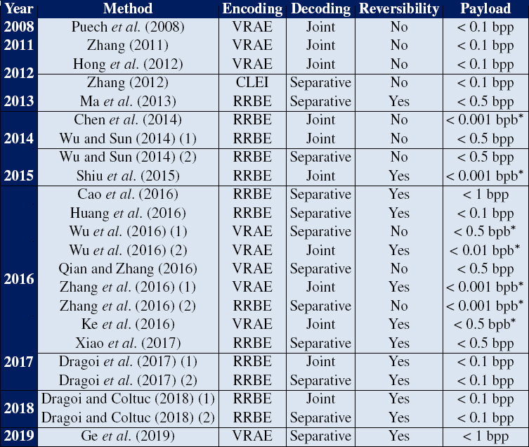
COMMENT ON TABLE 7.1.– Comparison of methods by encoding approach (RRBE or VRAE), decoding type (joint or separative), reversibility (in the strict sense of the term, i.e. ![]() and payload (in bpp, bits-per-pixel, or in bpb, bits-per-bit, for models marked with a ∗).
and payload (in bpp, bits-per-pixel, or in bpb, bits-per-bit, for models marked with a ∗).
7.6. A high-capacity data hiding approach based on MSB prediction
None of the methods presented above combine a high payload (greater than or equal to 1 bpp) and high visual quality (greater than 50 dB). In most cases, the values of the least significant bits (LSBs) are replaced to insert the bits of a secret message. However, when an image is encrypted, it is difficult to detect whether or not it contains a secret message. This is due to the fact that the pixel values of an encrypted image are generated pseudo-randomly. Thus, the correlation between a pixel and its neighbors is very low. For this reason, Puteaux and Puech (2018a) propose using the most significant bit (MSB) values instead of the LSB to embed the secret message, taking the opposite approach to previous state-of-the-art methods. We note that confidentiality in the encrypted domain remains the same and that, during the decoding phase, MSB values are simpler to predict than LSB values.
In this section, we shall begin by introducing the general scheme of this data hiding method. Unlike previous methods, the secret message is embedded by replacing the values of the MSBs. Since the values of the replaced MSBs are lost during the message insertion phase, we must be able to predict them without error during the decoding phase. Next, we provide a detailed presentation of two possible approaches, according to the most desirable characteristic: strict reversibility (PSNR → +∞) or maximum payload (1 bpp). The first approach is not perfectly reversible but allows the insertion of one bit of the secret message per pixel: this approach is known as CPE-HCRDH, high-capacity reversible data hiding approach with correction of prediction errors. The second approach, in which the original image is perfectly reconstructed but the inserted message must be adapted, is called EPE-HCRDH: high-capacity reversible data hiding approach with embedded prediction errors.
7.6.1. General description of the method
7.6.1.1. Encoding
The encoding phase consists of three steps: detection of prediction errors in the MSBs, accounting for prediction errors combined with image encryption, and embedding of the secret message by replacing the MSBs. An outline diagram of the encoding method is shown in Figure 7.7.
In this method, since the secret message is embedded by MSB substitution, the original MSB values are lost after the secret message is embedded. Thus, it is important to be able to predict these values without error during the decoding phase. To recover the original image, the previously reconstructed pixels are used to predict the current pixel value. The first step is thus to analyze the content of the original image to detect any prediction errors:
- – consider the current pixel p(i, j), with
 and its inverse value,
  As the difference between these two values is 128, the inverse value corresponds to the original value of p(i, j) but with an inversed MSB;
 - – using the values of the neighbors of p(i, j), we calculate the value pred(i, j), regarded as a predictor in the decoding phase;
- – we calculate the absolute difference between pred(i, j) and p(i, j) and between pred(i, j) and inv(i, j). The resulting values are noted Δ and Δinv and are such that:

- – we then compare the values of Δ and Δinv. If Δ < Δinv, then there is no prediction error, since the original value of p(i, j) is closer to the predictor than the inverse value. Otherwise, an error is identified and its location will be specified in a binary error location map, as shown in Figure 7.7.
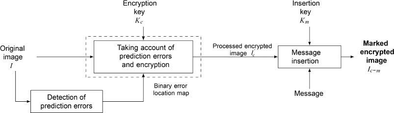
Figure 7.7. General scheme of the encoding method
Depending on the chosen approach, the binary error location map may be used in one of two ways. The original image may be pre-processed to correct prediction errors, resulting in an image I′, which is very similar to the original. The other option is to indicate the location of prediction errors in the encrypted domain after encrypting the original image, instead of correcting them.
In both cases, the clear image is encrypted using a stream approach, as described in section 7.3.2. This results in the encrypted pixels pe(i, j):
where s(i, j) is the byte corresponding to p(i, j) in a pseudo-random binary sequence and ⊕ is the exclusive-or operation.
Note that in the case of the error signaling approach, the encrypted image will be modified.
During the message insertion phase, using the data hiding key Km, the secret message is encrypted to prevent it from being detected in the marked encrypted image. Next, the pixels in the encrypted image are passed through in scanline order (left to right and top to bottom), and the MSB of each available pixel is replaced with a bit bk, with 0 ≤ k < m × n, from the secret message in order to obtain the corresponding pixel pe−m(i, j):
Note that only the first pixel cannot be marked, since its value cannot be predicted: this pixel is therefore left unchanged.
7.6.1.2. Decoding
Since the method is separable, the secret message can be extracted and the original clear image ![]() can be reconstructed independently during the decoding phase.
can be reconstructed independently during the decoding phase. ![]() is strictly identical to the original image I or to the pre-processed image I′, which is very similar to the original image, depending on the chosen approach. There are then three possible scenarios for the recipient of the data:
is strictly identical to the original image I or to the pre-processed image I′, which is very similar to the original image, depending on the chosen approach. There are then three possible scenarios for the recipient of the data:
- 1) the recipient only has the data hiding key Km;
- 2) the recipient only has the encryption key Ke;
- 3) the recipient has both keys.
A general outline of the decoding phase is shown in Figure 7.8.
If the recipient of the data only has the data hiding key Km, the pixels in the marked encrypted image will be read in scanline order and the MSB of each pixel will be extracted to obtain the bits of the encrypted secret message:
where 0 ≤ k < m × n and relates to the index of the extracted message bit.
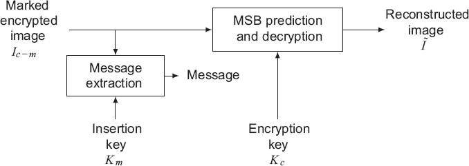
Figure 7.8. General outline of the decoding method
The corresponding clear version of the secret message is then obtained using the data hiding key.
In the second case, if the recipient of the data holds only the encryption key Ke, image ![]() can be reconstructed in the form it had prior to message insertion and encryption:
can be reconstructed in the form it had prior to message insertion and encryption:
- 1) the encryption key Ke is used to generate a pseudo-random binary sequence of m × n bytes s(i, j);
- 2) the pixels in the marked encrypted image are read in scanline order, and the seven LSB of each pixel are reconstructed by applying an exclusive-or between the marked encrypted value pe−m(i, j) and the corresponding byte s(i, j) in the pseudo-random binary sequence:
where ⊕ is the exclusive-or operation;
- 3) the value of the MSB is predicted in the following manner:
- - the value of the predictor pred(i, j) is calculated using the values of neighboring pixels that have already been reconstructed;
- - the two possible values of the original pixel are generated, with MSB = 0 and MSB = 1. The differences between these two values and pred(i, j) are calculated and noted Δ0 and Δ1:
- - the lowest value from Δ0 and Δ1 gives us the desired value of the original pixel:


7.6.2. The CPE-HCRDH approach
In the CPE-HCRDH approach, shown in Figure 7.9, the first step is to pre-process the original image to eliminate any prediction errors, enabling a high-quality reconstruction of the original image during the decoding phase. The pre-processed image is then encrypted. During the data hiding phase, each pixel in the encrypted image is marked with one bit of the message. Using this approach, a maximum payload of 1 bpp can be attained.
7.6.2.1. Choice of predictor
As we saw in section 7.6.1.1, the value of the current pixel is predicted using those of the previous pixels. In this approach, the mean value of the pixel to the left and the pixel above the current pixel is used as the predictor pred(i, j):
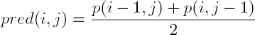
Note that a specific treatment is used for pixels in the first line and the first column.
Using the mean value as a predictor minimized the modification in the value of the current pixel in cases of error, notably when the difference between the value of the current pixel and that of one of its neighbors is large.
7.6.2.2. Image pre-processing
Once prediction errors have been detected, the original image I is pre-processed to generate an image I′ free from prediction errors. The value of the prediction error is observed for all pixels concerned, then the minimum modification required to correct the error in the current pixel is calculated. The modification used to eliminate all errors during the decoding phase is given in equation [7.28]:
The pre-processing steps applied to the original image to correct all prediction errors are shown in Algorithm 7.1.

Figure 7.9. Encoding using the CPE-HCRDH approach

The predicted image I′ is then encrypted. The secret message is inserted by replacing the MSB of each pixel in the encrypted image ![]() with a message bit, following equation [7.22]. Finally, the marked encrypted image
with a message bit, following equation [7.22]. Finally, the marked encrypted image ![]() is obtained, with a maximum payload of 1 bpp.
is obtained, with a maximum payload of 1 bpp.
7.6.2.3. Message extraction and image reconstruction
During decoding, to extract the secret message, the marked encrypted image ![]() is read and the MSB for each pixel is simply extracted using equation [7.23]. The original preprocessed image I′ can also be reconstructed without loss. To do this, the marked encrypted image
is read and the MSB for each pixel is simply extracted using equation [7.23]. The original preprocessed image I′ can also be reconstructed without loss. To do this, the marked encrypted image ![]() is decrypted to give the seven LSB of each pixel (equation [7.24]), then the value of the MSB is predicted by applying equations [7.25] and [7.26]. Note that the reconstructed image is very similar to the original image.
is decrypted to give the seven LSB of each pixel (equation [7.24]), then the value of the MSB is predicted by applying equations [7.25] and [7.26]. Note that the reconstructed image is very similar to the original image.
7.6.3. The EPE-HCRDH approach
In the IEPE-HCRDH approach, the main aim is to ensure perfect reconstruction of the original image. In this case, the payload may be significantly lower as the location of prediction errors must be indicated. The embedded message is modified in order to take account of the error location map, constructed during the error prediction detection phase. The original image is then encrypted without pre-processing, then the location of the prediction errors is inserted into the encrypted image. Bits of the secret message can then only be inserted into available pixels. At the end of the decoding process, the original image is reconstructed without loss due to the fact that prediction errors have been signaled: this results in a PSNR value which tends toward + ∞. A general overview of this approach is presented in Figure 7.10.
7.6.3.1. Predictor choice
For each pixel, two neighboring pixels may be used as predictors: the pixel on the left p(i, j − 1) and the pixel directly above p(i − 1, j). To identify which of these pixels to use as the predictor, the absolute value of their difference with the current pixel p(i, j) is calculated and the nearest value is selected:

In certain cases, the other value may be used to predict the inverse of the pixel inv(i, j) during error prediction, but the result remains the same. Note that the mean of the left and upper pixel may also be used as the predictor, as in the CPE-HCRDH approach, but the results obtained experimentally in this case were not as good.
7.6.3.2. Signaling the location of errors
During the prediction error detection stage, the locations of errors are indicated in a binary error location map, as described in section 7.6.1.1. Next, the original image I is encrypted, and the encrypted image Ie is adapted prior to data hiding in order to eliminate prediction errors. The image is divided into blocks of 8 pixels then read in scanline order. If there is at least one prediction error in a block, according to the binary error location map, the current block is flagged on both sides by replacing the MSB of each pixel in the previous and following blocks with a 1. In the current block, the MSB is replaced by a value of 1 if there is a prediction error and by 0 otherwise, as shown in Figure 7.11. If there are no errors in the current block and if it is not used for flagging purposes, then all eight pixels in this block will be used for message embedding, as described in section 7.6.1.1. If errors are found in two adjacent blocks, the flag indicating the end of the error is shifted to the next error-free block. This reduces the payload loss since flags may be used for more than one prediction error. Note that smaller blocks may be used, but the statistical risk of part of the secret message being identified as a flag is increased. Using blocks of eight pixels gives a good tradeoff between payload loss and the risk of false alarms. Few pixels cannot be marked with bits of the secret message, and the probability of part of the message being mistaken for a flag is very low ![]()

Figure 7.10. Encoding using the EPE-HCRDH approach
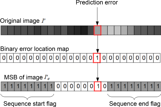
Figure 7.11. Signaling prediction errors
This method produces an encrypted image ![]() with embedded prediction errors. With this type of processing, during the insertion phase, the MSB values of each pixel can be extracted and the error location information can be used to detect which pixels can be marked with secret message bits (i.e. in all blocks where there are no prediction errors and that are not used as flags). All available pixels are then marked to obtain the encrypted marked image Ie−m, using equation [7.22].
with embedded prediction errors. With this type of processing, during the insertion phase, the MSB values of each pixel can be extracted and the error location information can be used to detect which pixels can be marked with secret message bits (i.e. in all blocks where there are no prediction errors and that are not used as flags). All available pixels are then marked to obtain the encrypted marked image Ie−m, using equation [7.22].
7.6.3.3. Message extraction and image reconstruction
The secret message can be extracted during the decoding process using the following steps:
- – the pixels of the marked encrypted image Ie−m are read and the MSB value for each pixel is extracted, following equation [7.23], and stored. All bits extracted up until the first sequence of 8 bits equal to 1 are considered to belong to the secret message;
- – a sequence of 8 bits equal to 1 indicates the start of a sequence that includes prediction errors. Given that the following pixels were not marked during the message insertion phase, pixels will be skipped over up until the next sequence of eight MSBs equal to 1, which indicates the end of the error sequence;
- – this process is repeated throughout the whole image.
Furthermore, since this method is entirely reversible, the original image I is perfectly reconstructed. The marked encrypted image Ie−m is first decrypted to obtain the seven LSBs for each pixel using equation [7.24]. The values of the MSB of each pixel are then predicted using equations [7.25] and [7.26].
7.6.4. Experimental results for both approaches
The two approaches were applied to the same original image of 512 × 512 pixels, shown in Figure 7.12, taken from the BOWS-2 database (Bas and Furon 2008).

Figure 7.12. Original image I taken from the BOWS-2 database (Bas and Furon 2008)
Figure 7.13 shows the results obtained using the CPE-HCRDH approach, while Figure 7.14 shows the results obtained using the EPE-HCRDH approach. The location of pixels concerned by an MSB prediction error is shown in white in Figures 7.13(a) and 7.14(a). We see that the number and location of prediction errors differ, since the predictors used in each case are not the same, as we saw in sections 7.6.2.1 and 7.6.3.1; nevertheless, they are of a similar order of magnitude.
In the CPE-HCRDH approach (Figure 7.13(a)), the MSB of certain pixels in the original image are wrongly predicted if pixel values are not adjusted during the pre-processing phase. In the EPE-HCRDH approach (Figure 7.14(a)), the pixels concerned by prediction errors (in white) cannot be marked. Furthermore, the pixels in gray cannot be marked either as they are used as flags or form part of a sequence containing one or more errors. Note that prediction errors are often encountered on contours; moreover, a single block can sometimes contain multiple errors. In this case, the payload reduction is lower. The histogram in Figure 7.13(b) shows the distribution of prediction errors when the CPE-HDRDH approach is used, alongside the modifications that must be applied to the pixels in order to remove these errors. Figure 7.13(c) shows the same image after pre-processing using Algorithm 7.1. We see that the pre-processed image is very similar to the original image: the PSNR value is 46.87 dB, with an SSIM of 0.9997. Figure 7.13(d) shows the pre-processed image after stream encryption using the encryption key. Figure 7.14(b) shows the encrypted image obtained using the EPE-HCRDH approach, and Figure 7.14(c) corresponds to this image after prediction errors have been flagged. The content of the original image and the locations of the prediction error are visually confidential. Figures 7.13(e) and 7.14(d) show the marked encrypted images obtained at the end of the encoding phase, after embedding a secret message. In the CPE-HCRDH approach, each pixel in the pre-processed image is used to embed one bit of the secret message (payload = 1 bpp). In the EPE-HCRDH approach, pixels are marked to signal prediction errors and although the payload is lower, it is still high, with a value of 0.9220 bpp. Figures 7.13(f) and 7.14(e) show the reconstructed images after data extraction. Figure 7.13(f) is identical to the pre-processed image (PSNR = 46.87 dB), while the original image is perfectly reconstructed in the case of EPE-HCRDH, resulting in a PSNR which tends toward + ∞ and an SSIM of 1 (Figure 7.14(e)). Finally, note that the secret message is extracted without error in both cases.

Figure 7.13. Experimental results obtained using the CPE-HCRDH approach, with a payload of 1 bpp: a) location of errors, number of errors = 1 242 (0.47 %); b) histogram of prediction errors, c) pre-processed image  PSNR = 46.87 dB; d) encrypted image
  marked encrypted image
  reconstructed image I’, PSNR = 46.87 dB, SSIM = 0.9997

Figure 7.14. Experimental results obtained using the EPE-HCRDH approach: a) location of unmarked pixels (errors and flags), number of errors = 1 225 (0.46 %); b) encrypted image Ie; c) encrypted image  with flagged errors; d) marked encrypted image Ie−m with payload = 0.9220 bpp; e) reconstructed image
  SSIM = 1
The two proposed approaches were also applied to 10,000 grayscale images of size 512 × 512 pixels, taken from the BOWS-2 database (Bas and Furon 2008). Note that these images present high statistical variability in terms of content. The results obtained for this image database are shown in Table 7.2. In 6.3% of cases, when there is no prediction error (i.e. all differences between the original pixels and their predictors are less than or equal to 64), both approaches are fully reversible. In this case, the original images are reconstructed without error, giving a PSNR which tends toward + ∞ and an SSIM equal to 1. Moreover, all of the pixels in the images can be marked in this case, giving a maximum payload of 1 bpp. In other cases, for the CPE-HCRDH approach, the payload value is unchanged, but the original images cannot be reconstructed without loss because a certain number of pixels have to be modified in order to correct prediction errors. Nevertheless, for low contrast images, the quality of the reconstructed images is high, with an average PSNR of 57.4 dB and SSIM of almost 1 (0.9998). Moreover, the PSNR is higher than 40 dB in 98.64% of cases, indicating very good image quality. The EPE-HCRDH approach, on the other hand, is fully reversible for all images, with a PSNR tending to + ∞ and a SSIM of 1. Even if the presence of prediction errors means that not all pixels are labeled (especially in the worst case scenario), the payload remains high, with an average value of 0.9681 bpp. The payload exceeds 0.9 bpp in 92.19% of cases.
Table 7.2. Performance of the two approaches using the BOWS-2 database (10,000 images) (Bas and Furon 2008)


Figure 7.15. Payload measures for the EPE-HCRDH approach, obtained for 500 images in the BOWS-2 database (Bas and Furon 2008)
For ease of visualization, Figure 7.15 shows the payload results obtained using the EPE-HCRDH approach for 500 of the 10,000 images in the BOWS-2 (Bas and Furon 2008) database, selected at random.
7.7. Conclusion
In this chapter, we presented the challenges involved in hiding data within encrypted images. Following a description of different applications for analytical and processing purposes in the encrypted domain, we examined the reasons and applicative contexts for data hiding methods, before presenting the main classes and characteristics of the existing methods. We then presented the state of the art in this domain, showing, via a comparative table of methods, that none of the existing approaches combine a large payload with perfect reconstruction of the original image. Finally, we gave a detailed description of the method designed by Puteaux and Puech (2018a), where a very good compromise between these two criteria is obtained. Both proposed approaches offer a payload of the order of 1 bpp and very high quality image reconstruction.
This method takes a different approach to other state-of-the-art methods, achieving very good results. As a result, a large number of new “high-capacity” methods have built on this technique to offer even greater increases in payload (Puyang et al. 2018). Some authors have notably suggested a recursive reading and treatment of all of the binary planes in an image, starting from the MSB plane (Puteaux and Puech 2018b, 2020; Yin et al. 2019). In this way, the strong correlation between pixels in the clear domain is fully exploited, and a payload of over 2.4 bpp can be achieved (Puteaux and Puech 2020). Current research work is focused on developing high-capacity data hiding methods which exploit the homomorphic properties of public key encryption approaches.
In this chapter, we chose to consider data hiding methods applied to non-compressed digital images. It is important to note that extensions have been proposed for JPEG images (Qian et al. 2014), videos (Xu et al. 2013) and 3D objects (Jiang et al. 2017).
7.8. References
Bas, P. and Furon, T. (2008). Image database of BOWS-2 [Online]. Available at: http://bows2.ec-lille.fr/.
Blakley, G.R. (1979). Safeguarding cryptographic keys. Proceedings of the National Computer Conference. AFIPS, New York, USA.
Bouslimi, D., Coatrieux, G., Cozic, M., Roux, C. (2012). A joint encryption/water-marking system for verifying the reliability of medical images. IEEE Transactions on Information Technology in Biomedicine, 16(5), 891–899.
Cao, X., Du, L., Wei, X., Meng, D., Guo, X. (2016). High capacity reversible data hiding in encrypted images by patch-level sparse representation. IEEE Transactions on Cybernetics, 46(5), 1132–1143.
Chen, Y.-C., Shiu, C.-W., Horng, G. (2014). Encrypted signal-based reversible data hiding with public key cryptosystem. Journal of Visual Communication and Image Representation, 25(5), 1164–1170.
Daemen, J. and Rijmen, V. (2002). The Design of Rijndael: AES – The Advanced Encryption Standard. Springer, Berlin, Germany.
Dragoi, I.C. and Coltuc, D. (2018). Reversible data hiding in encrypted images based on reserving room after encryption and multiple predictors. Proceedings of the International Conference on Acoustics, Speech and Signal Processing (ICASSP). IEEE, Calgary, Canada.
Dragoi, I.C., Coanda, H.-G., Coltuc, D. (2017). Improved reversible data hiding in encrypted images based on reserving room after encryption and pixel prediction. Proceedings of the 25th European Signal Processing Conference (EUSIPCO). EURASIP, Kos, Greece.
Dufaux, F. and Ebrahimi, T. (2008). Scrambling for privacy protection in video surveillance systems. IEEE Transactions on Circuits and Systems for Video Technology, 18(8), 1168–1174.
Erkin, Z., Piva, A., Katzenbeisser, S., Lagendijk, R.L., Shokrollahi, J., Neven, G., Barni, M. (2007). Protection and retrieval of encrypted multimedia content: When cryptography meets signal processing. EURASIP Journal on Information Security, 1–20.
Ferreira, B., Rodrigues, J., Leitao, J., Domingos, H. (2015). Privacy-preserving content-based image retrieval in the cloud. Proceedings of the 34th Symposium on Reliable Distributed Systems (SRDS). IEEE, Montreal, Canada.
Ge, H., Chen, Y., Qian, Z., Wang, J. (2019). A high capacity multi-level approach for reversible data hiding in encrypted images. IEEE Transactions on Circuits and Systems for Video Technology, 29(8), 2285–2295.
Hey, T., Tansley, S., Tolle, K. (2009). The Fourth Paradigm: Data-Intensive Scientific Discovery. Microsoft Research, Redmond, USA.
Hong, W., Chen, T.-S., Wu, H.-Y. (2012). An improved reversible data hiding in encrypted images using side match. IEEE Signal Processing Letters, 19(4), 199–202.
Hsu, C.-Y., Lu, C.-S., Pei, S.-C. (2012). Image feature extraction in encrypted domain with privacy-preserving SIFT. IEEE Transactions on Image Processing, 21(11), 4593–4607.
Huang, F., Huang, J., Shi, Y.-Q. (2016). New framework for reversible data hiding in encrypted domain. IEEE Transactions on Information Forensics and Security, 11(12), 2777–2789.
Jain, A.K., Lee, J.-E., Jin, R., Gregg, N. (2009). Content-based image retrieval: An application to tattoo images. Proceedings of the 16th International Conference on Image Processing (ICIP). IEEE, Cairo, Egypt.
Jiang, R., Zhou, H., Zhang, W., Yu, N. (2017). Reversible data hiding in encrypted three-dimensional mesh models. IEEE Transactions on Multimedia, 20(1), 55–67.
Ke, Y., Zhang, M., Liu, J. (2016). Separable multiple bits reversible data hiding in encrypted domain. Proceedings of the International Workshop on Digital Watermarking. IWDW, Beijing, China.
Ke, Y., Zhang, M., Liu, J., Su, T., Yang, X. (2018). A multilevel reversible data hiding scheme in encrypted domain based on LWE. Journal of Visual Communication and Image Representation, 54, 133–144.
Li, S., Chen, G., Mou, X. (2005). On the dynamical degradation of digital piecewise linear chaotic maps. International Journal of Bifurcation and Chaos, 15(10), 3119–3151.
Li, X., Li, J., Li, B., Yang, B. (2013). High-fidelity reversible data hiding scheme based on pixel-value-ordering and prediction-error expansion. Signal Processing, 93(1), 198–205.
Liu, W., Zeng, W., Dong, L., Yao, Q. (2009). Efficient compression of encrypted grayscale images. IEEE Transactions on Image Processing, 19(4), 1097–1102.
Lu, W., Swaminathan, A., Varna, A.L., Wu, M. (2009a). Enabling search over encrypted multimedia databases. Proceedings of SPIE – Electronic Imaging. International Society for Optics and Photonics, San Jose, USA.
Lu, W., Varna, A.L., Swaminathan, A., Wu, M. (2009b). Secure image retrieval through feature protection. Proceedings of the International Conference on Acoustics, Speech and Signal Processing (ICASSP). IEEE, Taipei, Taiwan.
Ma, K., Zhang, W., Zhao, X., Yu, N., Li, F. (2013). Reversible data hiding in encrypted images by reserving room before encryption. IEEE Transactions on Information Forensics and Security, 8(3), 553–562.
Naor, M. and Shamir, A. (1994). Visual cryptography. Proceedings of the Workshop on the Theory and Application of Cryptographic Techniques. IACR, Perugia, Italy.
Paillier, P. (1999). Public-key cryptosystems based on composite degree residuosity classes. Proceedings of the International Conference on the Theory and Applications of Cryptographic Techniques. IACR, Prague, Czech Republic.
Pavlopoulou, C., Kak, A.C., Brodley, C.E. (2003). Content-based image retrieval for medical imagery. In Medical Imaging 2003: PACS and Integrated Medical Information Systems: Design and Evaluation, Huang, H.K., Ratib, O.M. (eds). International Society for Optics and Photonics, Bellingham, USA.
Poh, G.S. and Martin, K.M. (2009). An efficient buyer-seller watermarking protocol based on Chameleon encryption. Proceedings of the 7th International Workshop on Digital Watermarking. IWDW, Busan, South Korea.
Preishuber, M., Hütter, T., Katzenbeisser, S., Uhl, A. (2018). Depreciating motivation and empirical security analysis of chaos-based image and video encryption. IEEE Transactions on Information Forensics and Security, 13(9), 2137–2150.
Puech, W., Chaumont, M., Strauss, O. (2008). A reversible data hiding method for encrypted images. In Security, Forensics, Steganography, and Watermarking of Multimedia Contents, Delp III, E.J., Wong, P.W. (eds). International Society for Optics and Photonics, Bellingham, USA.
Puteaux, P. and Puech, W. (2018a). An efficient MSB prediction-based method for high-capacity reversible data hiding in encrypted images. IEEE Transactions on Information Forensics and Security, 13(7), 1670–1681.
Puteaux, P. and Puech, W. (2018b). EPE-based huge-capacity reversible data hiding in encrypted images. Proceedings of the Workshop on Information Forensics and Security. IEEE, Hong Kong, China.
Puteaux, P. and Puech, W. (2020). A recursive reversible data hiding in encrypted images method with a very high capacity. IEEE Transactions on Multimedia, 23, 636–650.
Puyang, Y., Yin, Z., Qian, Z. (2018). Reversible data hiding in encrypted images with two-MSB prediction. Proceedings of the Workshop on Information Forensics and Security. IEEE, Hong Kong, China.
Qian, Z. and Zhang, X. (2016). Reversible data hiding in encrypted images with distributed source encoding. IEEE Transactions on Circuits and Systems for Video Technology, 26(4), 636–646.
Qian, Z., Zhang, X., Wang, S. (2014). Reversible data hiding in encrypted JPEG bitstream. IEEE Transactions on Multimedia, 16(5), 1486–1491.
Qian, Z., Xu, H., Luo, X., Zhang, X. (2018). New framework of reversible data hiding in encrypted JPEG bitstreams. IEEE Transactions on Circuits and Systems for Video Technology, 29(2), 351–362.
Shamir, A. (1979). How to share a secret. Communications of the ACM, 22(11), 612–613.
Shannon, C.E. (1948). A mathematical theory of communication. The Bell System Technical Journal, 27, 379–423.
Shiu, C.-W., Chen, Y.-C., Hong, W. (2015). Encrypted image-based reversible data hiding with public key cryptography from difference expansion. Signal Processing: Image Communication, 39, 226–233.
Slepian, D. and Wolf, J. (1973). Noiseless coding of correlated information sources. IEEE Transactions on Information Theory, 19(4), 471–480.
Thien, C. and Lin, J. (2002). Secret image sharing. Computers & Graphics, 26(5), 765–770.
Wang, Z., Bovik, A.C., Sheikh, H.R., Simoncelli, E.P. (2004). Image quality assessment: From error visibility to structural similarity. IEEE Transactions on Image Processing, 13(4), 600–612.
Wong, K.S. and Tanaka, K. (2014). Data embedding for geo-tagging any contents in smart device. Proceedings of the Region 10 Symposium. IEEE, Kuala Lumpur, Malaysia.
Wu, X. and Sun, W. (2014). High-capacity reversible data hiding in encrypted images by prediction error. Signal Processing, 104, 387–400.
Wu, Y., Noonan, J.P., Agaian, S. (2011). NPCR and UACI randomness tests for image encryption. Cyber Journals: Multidisciplinary Journals in Science and Technology, Journal of Selected Areas in Telecommunications, 1(2), 31–38.
Wu, H.-T., Cheung, Y.-M., Huang, J. (2016). Reversible data hiding in Paillier cryptosystem. Journal of Visual Communication and Image Representation, 40, 765–771.
Xia, Z., Wang, X., Zhang, L., Qin, Z., Sun, X., Ren, K. (2016). A privacy-preserving and copy-deterrence content-based image retrieval scheme in cloud computing. IEEE Transactions on Information Forensics and Security, 11(11), 2594–2608.
Xiao, D., Xiang, Y., Zheng, H., Wang, Y. (2017). Separable reversible data hiding in encrypted image based on pixel value ordering and additive homomorphism. Journal of Visual Communication and Image Representation, 45, 1–10.
Xu, D., Wang, R., Shi, Y.Q. (2013). Reversible data hiding in encrypted H.264/avc video streams. Proceedings of the International Workshop on Digital Watermarking. IWDW, Auckland, New Zealand.
Yin, Z., Xiang, Y., Zhang, X. (2019). Reversible data hiding in encrypted images based on multi-MSB prediction and Huffman coding. IEEE Transactions on Multimedia, 22(4), 874–884.
Zhang, X. (2011). Reversible data hiding in encrypted image. IEEE Signal Processing Letters, 18(4), 255–258.
Zhang, X. (2012). Separable reversible data hiding in encrypted image. IEEE Transactions on Information Forensics and Security, 7(2), 826–832.
Zhang, X., Long, J., Wang, Z., Cheng, H. (2016). Lossless and reversible data hiding in encrypted images with public-key cryptography. IEEE Transactions on Circuits and Systems for Video Technology, 26(9), 1622–1631.