
Chapter 8: Standard Assembly Mates
Most of the products that we interact with in our daily lives, such as laptops, phones, and cameras, are made up of many different components that have been put together; that is, they have been assembled. One of the major elements of mastering SOLIDWORKS is being able to use SOLIDWORKS assemblies, which allow us to put multiple parts together to create a single artifact. In this chapter, we will cover basic SOLIDWORKS assemblies and, in particular, standard mates.
In this chapter, we will cover the following topics:
- Opening assemblies and adding parts
- Understanding and applying non-value-oriented standard mates
- Understanding and applying value-driven standard mates
- Utilizing materials and mass properties for assemblies
By the end of this chapter, we will be able to put different parts together to form an assembly. The objective of this chapter is to get us to generate complex artifacts by linking different parts together and creating an assembly using standard mates.
Technical requirements
In this chapter, you will need to have access to the SOLIDWORKS software. The files for this chapter can be found at the following GitHub repository: https://github.com/PacktPublishing/Learn-SOLIDWORKS-Second-Edition/tree/main/Chapter08.
Check out the following video to see the code in action: https://bit.ly/31ZCRra
Opening assemblies and adding parts
In this section, we will take our first steps toward working with SOLIDWORKS assemblies. We will cover what SOLIDWORKS assemblies are, how to start an assembly file, and how can we add a variety of components to our assembly file. Opening an assembly file and adding different parts to it is the first step we need to take when we start any assembly.
Defining SOLIDWORKS assemblies
There are three main sections of SOLIDWORKS: parts, assemblies, and drawings. For each type, SOLIDWORKS creates a different file type with different file extensions. For assemblies, the file extension is .SLDASM, while a part has a file extension of .SLDPRT. In Chapter 10, Basic SOLIDWORKS Drawing Layout and Annotations, we will cover drawings, which have the file extension .SLDDRW.
With an assembly file, we can link more than one part file together to form one product. The following figures highlight two examples of assembly files. The following figure shows a simple assembly that consists of only three parts. We can see each and every part since they are highlighted by solid lines and borders that have been filled in with a variety of colors:

Figure 8.1 – A simple assembly of three parts
The following assembly is more complex than the first one. It is a mechanical assembly that consists of over 50 different parts:

Figure 8.2 – An assembly of 50 parts
The different parts interact with each other via mates. Mates are very similar to the relations we used in sketching, for example, coincident, perpendicular, and tangent. Now that we know what assemblies are, we can move on and create our first assembly file.
Starting a SOLIDWORKS assembly file and adding parts to it
To demonstrate how to start an assembly file and add parts to it, we will start an assembly file and add the following parts to it. Make sure that you download the files that accompany this chapter. The parts you will download are as follows:
- A small triangular part:
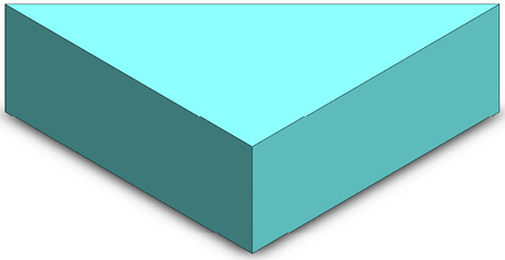
Figure 8.3 – The rectangular prism is included in this chapter's downloads
- A larger base part, which will house the smaller triangular part:
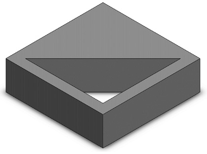
Figure 8.4 – The part file for this shape is included in the chapter's downloads
Now that you've downloaded these parts onto your computer, we can start opening our assembly file.
Starting an assembly file
To start an assembly file, follow these steps:
- Select New from the top of the SOLIDWORKS interface, as shown in the following screenshot:

Figure 8.5 – Where to start a new file
- Select Assembly and click OK:
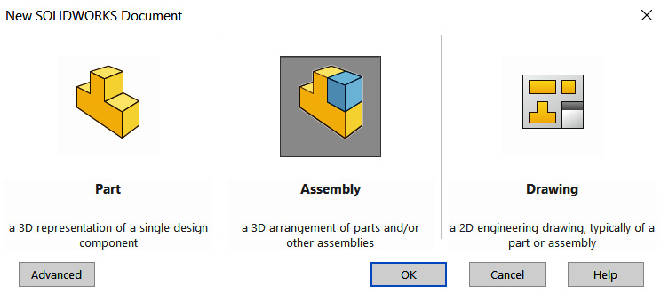
Figure 8.6 – A window showing the different new file types you can start with
Now that we have opened our assembly file, we can add the two parts we downloaded to it. We will do that next.
Adding parts to the assembly file
To add our two parts to the assembly file, follow these steps:
- As soon as we open a new assembly file, SOLIDWORKS will prompt us to select a part to be added to the assembly. From here, you can navigate to the Base.SLDPRT file, which can be found in the SOLIDWORKS parts attached to this chapter. Click Open after selecting the file. Alternatively, we can double-click on the file to open it:

Figure 8.7 – The browser window to open a part in an assembly
Important Note
If SOLIDWORKS does not prompt you to add a part automatically, you can use the Insert Components option, as shown in Figure 8.9.
- The part will appear in the assembly's canvas. At the bottom of the page, we will see some options that can help us orient the part if needed. Once we are satisfied with the part's orientation, we can left-click on the canvas using the mouse to place the part. Then, we need to click on the green check mark, which can be found at the top right or the top left of the page, as shown in the following screenshot:

Figure 8.8 – The part appearing in the canvas after inserting it in the assembly file
- To add the second part, we can click on Insert Components, as highlighted in the following screenshot. Now, navigate to the other part, that is, Triangle.SLDPRT. Select it, and click Open:

Figure 8.9 – The location of the Insert Components command
- The triangle will appear on the canvas as well. We can left-click to place the part in the assembly. We will end up with the two parts on the canvas, as shown in the following figure. You may have a different placement for these two parts than what's shown here, though. This is not an issue at this point:
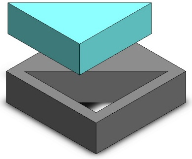
Figure 8.10 – The two parts will be in the assembly canvas
This concludes this exercise of adding parts to our assembly file. Before we move on, however, let's mention three key points when it comes to adding parts to our assembly:
- Fixed parts: The first part you insert into the assembly file is a fixed part by default. Fixed parts don't move in the assembly environment and are fully defined.
- Floated parts: The second part that's inserted is a floating part by default. Floating parts can be moved around the assembly environment since they are not defined. We will use mates to define floating parts later in this chapter.
- Dragging parts: You can click and hold the second part (triangle) and move it around the canvas. The first part is fixed by default, and so it cannot be moved.
We can change any part's status from fixed to floating and vice versa by right-clicking on the part and selecting the Float or Fix command. The Float command is highlighted in the following screenshot:
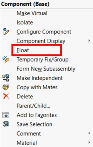
Figure 8.11 – The Float command location
Important Note
If the part is fixed, we will see the Float command, as shown in Figure 8.11. However, if the part is floating, then we will see the Fix command instead to make the part fixed.
At this point, we have inserted our two parts into an assembly file. However, the parts hold no linkage to each other. Next, we will look at mates, which will cause our parts to interlink.
Understanding mates
Mates are similar to sketch relations, but they act on assemblies. They govern how different parts interact with each other or move in relation to each other. As an example, examine the keys on a computer keyboard. Each key is stationed in a specific location and restrained by specific movements, such as up and down. We can think of this positioning and movement as being governed by an assembly's mates.
There are three categories of mates in SOLIDWORKS: standard mates, advanced mates, and mechanical mates. We will only cover standard mates in this chapter. Standard mates provide the following options:
Some standard mates require us to input a numerical value, such as the mate's distance and angle. We can refer to these as value-oriented mates. The rest of the mates do not require a numerical value. We can refer to these as non-value-oriented mates. We will learn more about these next.
Understanding and applying non-value-oriented standard mates
In this section, we will start linking different parts together in an assembly using the non-value-oriented standard mates. We will learn about the coincident, parallel, perpendicular, tangent, concentric, and lock mates. These mates don't need a numerical value input to be applied to them; instead, they are constructed based on their relationship with different geometrical elements. In this section, we will learn what those mates are and how to apply them. We will also cover the different levels of defining an assembly. We will start by defining each of those non-value-oriented standard mates.
Defining the non-value-oriented standard mates
The non-value-oriented standard mates are coincident, parallel, perpendicular, tangent, concentric, and lock. These are special in that they don't require any numerical input to be applied to them or defined for them. They are very similar to the sketching relations we applied while sketching. Here is a brief explanation of each standard mate:
- Coincident: This allows a coincident relation between two surfaces, a line and a point, and two lines.
- Parallel: This allows us to set two surfaces, two edges, or a surface and an edge so that they're parallel to each other.
- Perpendicular: This allows us to set two surfaces, two edges, or a surface and an edge so that they're perpendicular to each other.
- Tangent: This allows two curved surfaces to have a tangent between each other. This can also happen between a curved surface and an edge, as well as a straight surface.
- Concentric: This allows two curves to have the same center.
- Lock: This locks two parts together. When two parts are locked, they will copy each other's movements.
Now that we know what these standard mates do, we will start applying them in order to link different parts of our assembly. We will start with the coincident and perpendicular mates.
Applying the coincident and perpendicular mates
To explore how to make the mates coincident and perpendicular, we will make the assembly that's shown in the following figure. The assembly is made out of two parts – a Base part and a Triangle part. We opened these parts in an assembly file earlier in this chapter. We will continue from there:
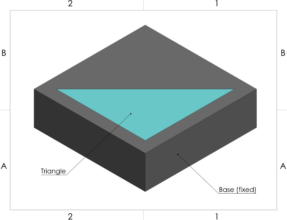
Figure 8.12 – The final assembly we will reach in this exercise
If you are starting over, you can download the two parts from the files for this chapter and open them in an assembly file. Our starting point will be having these two parts arranged on an assembly canvas, as shown here:

Figure 8.13 – The two parts placed in an assembly without mates
Now that we have the two parts in our assembly, we will apply the mates. We will start with the coincident mate, followed by the perpendicular mate.
Applying the coincident mate
To apply the coincident mate to our assembly, follow these steps:
- To apply mates, select the Mate command, which can be found under the Assembly command, as shown in the following screenshot:

Figure 8.14 – The location of the Mate command
- After selecting Mate, we will see a PropertyManager on the left-hand side of the screen. At this point, we will be asked to select which elements we want to mate. This can include surfaces, edges, and points. For this selection, we'll select the top surfaces of the base and the triangle, as shown in the following figure. These will fill in the Mate Selections space, which is highlighted in red in the following figure:
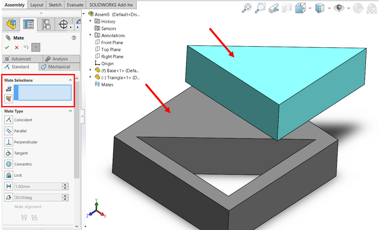
Figure 8.15 – The surfaces we can mate together
After the selection, we will see that the two parts move in relation to each other. Also, one mate will be selected automatically. In this case, the mate will be Coincident. We can change this mate if we want to use another one. However, in this case, Coincident will work for us. Our canvas will look as follows. To apply the mate, click on the green check mark on top of the mate's PropertyManager:

Figure 8.16 – The mate will be previewed in the canvas after application
Tip
To check what effect the applied mate has, click and hold the triangle and move it around. We will see that the movement of the part has been restricted due to the applied mate.
When we try moving the triangle around the canvas, we will notice that it can only move sideways to the base. However, it won't move up and down relative to the base. Now, let's apply another coincident mate to restrain the triangle more. Note that the Mate command is still active, which means we can apply more mates.
- Select the edges shown in the following figure. These are the outer edges of the triangle and the inner edge of the base. Again, SOLIDWORKS will interpret that we want the coincident mate and automatically apply it:

Figure 8.17 – The selection of the coincident mate
After selecting these two edges, we will see the following screenshot (Figure 8.18). Before applying the mate, please take note of the following:
- In the canvas, the two parts will move to preview the mate. Make sure that the preview matches our needs, as indicated with A in Figure 8.18.
- In the Mate Selections list in the PropertyManager, we can double-check whether we have selected two edges. If not, we can delete the undesired selections there. This is indicated with B in the following screenshot.
- In the Standard Mate selection in the PropertyManager, we can double-check that the selected mate is what we want to apply. If we want to use another mate, we can select it from there. This check is indicated with the letter C in the following screenshot:

Figure 8.18 – Different checks to ensure we applied the correct mate
- After conducting all the checks, we can click on the green check mark to apply the mates.
Tip
The pin icon next to the red cross allows you to keep the mate PropertyManager visible after applying the mate, making it faster to apply multiple mates one after the other.
This concludes our application of the coincident mate. Next, we will apply the perpendicular mate to our assembly.
Applying the perpendicular mate
To find out what restraints are missing from our assembly, we can click and hold the triangle and drag it. We will see that the triangle is hinged at the corner we just mated. To restrain this movement, we can apply the perpendicular mate between the faces, as shown in the following figure:

Figure 8.19 – The surface selection to apply the perpendicular mate
To apply the mate, follow these steps:
- Select the Mate command and then select the Perpendicular mate.
- Select the two faces under Mate Selections. Our view will look as follows. Again, before applying the mate, note the position of the parts, the mate selection, and the selected standard mates:

Figure 8.20 – The mate PropertyManager and a preview of the perpendicular mate
- Click on the green check mark to apply the mate.
- Since we don't need to apply any more mates, we can close the mate's PropertyManager by pressing the Esc key on the keyboard or clicking the red cross at the top of the PropertyManager.
At this point, our assembly will look as follows. Note that if we try to drag the triangle in any direction, it won't move. This indicates that our assembly is now fully defined:
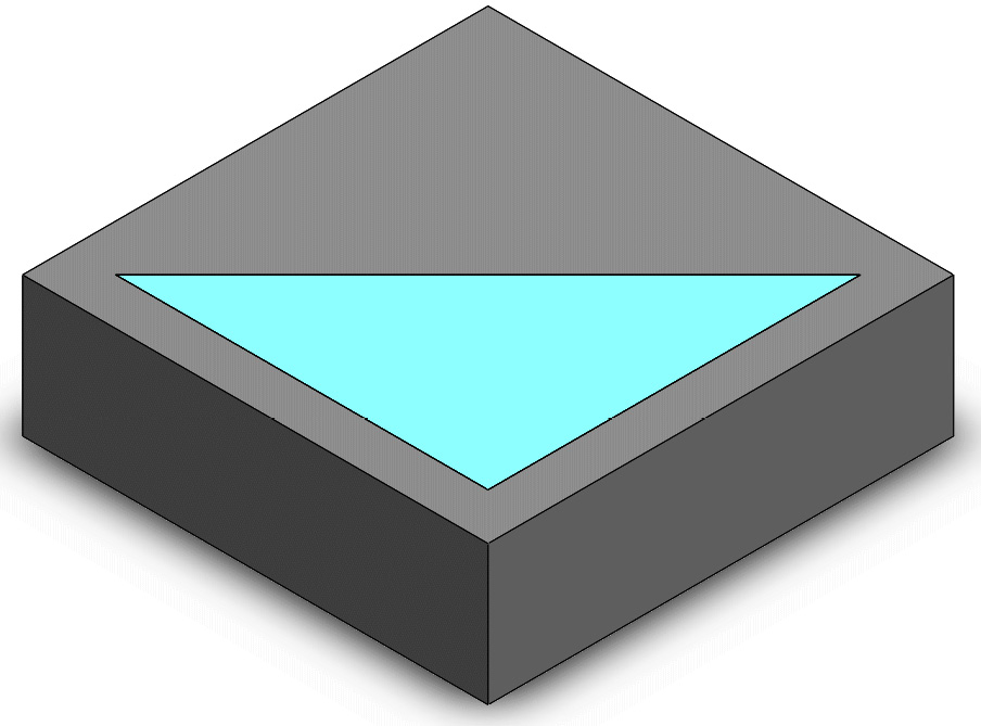
Figure 8.21 – The final look of our assembly
This concludes the application of the coincident and perpendicular mates to our assembly. We will follow the same procedure to apply all the other mates. While applying the coincident and perpendicular mates, we learned about the following:
- How to access the mate command
- How to select different elements and apply the mates to restrain them
- How to check for unrestrained movements by holding and dragging parts
We have just finished fully defining our assembly by using the coincident and perpendicular mates. Next, we will work on another assembly, which will involve the parallel, tangent, concentric, and lock mates.
Applying the parallel, tangent, concentric, and lock mates
In this section, we will explore how to apply the parallel, tangent, concentric, and lock mates. To do that, we will apply the mates that are shown in the following figure. We will refer to this drawing as we apply the different mates:
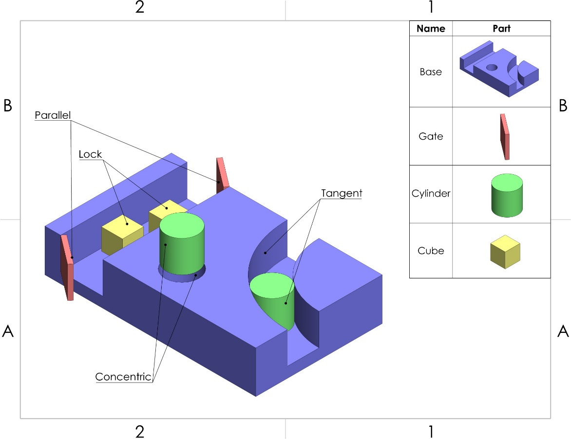
Figure 8.22 – The assembly we will work on in this exercise
To start, download the parts and the assembly file attached to this chapter. Our starting point, which is where we will apply all the mates, will be from the attached assembly file, which looks as follows:
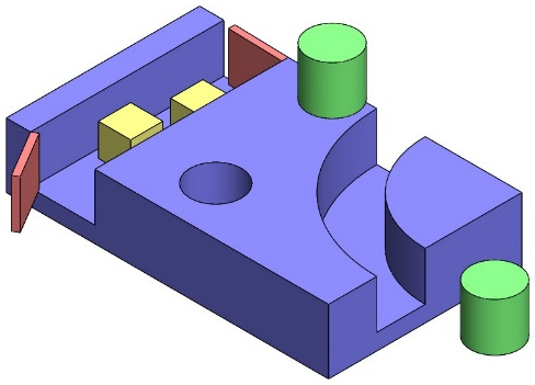
Figure 8.23 – The starting point of this exercise from the downloadable files
The attached assembly file already has a few coincident mates applied to it. The procedure of applying all the standard mates is similar, so we won't go into too much detail regarding the next four mates. Next, we will apply the Parallel, Tangent, Concentric, and Lock mates.
Applying the parallel mate
In this section, we will apply the parallel mate to the two gates that were shown in the initial drawing. These are also highlighted in the following figure. To do this, follow these steps:
- Go to the Mate command and select the Parallel mate.
- Under Mate Selections, select the two faces shown in the following figure:
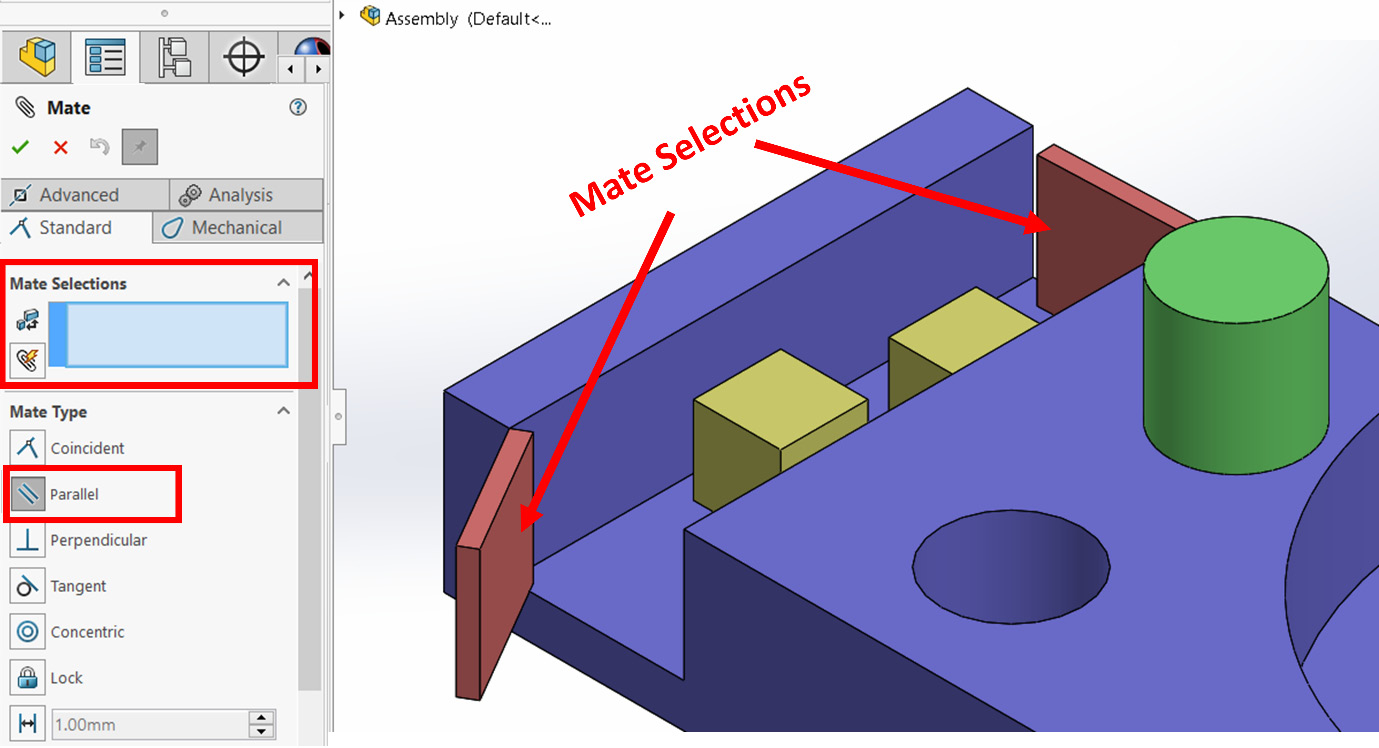
Figure 8.24 – The mate selection for the parallel mate
Important Note
The positions of the gates will shift as the mate takes effect.
- Apply the mate by clicking on the green check mark.
After applying the mate, it's good practice to drag the gates to see what effect it has. You will notice that, as we move one gate, the other gate will also move to keep the two faces parallel to each other. In this example, we applied the parallel mate to two faces, but we can also apply the mate in the same way to two straight edges or an edge with a face.
This concludes this exercise on applying the parallel mate. Next, we will start applying the tangent mate.
Applying the tangent mate
In this section, we will apply the tangent mate to the cylinder and base that were highlighted in the initial drawing. To do this, follow these steps:
- Go to the Mate command and select the Tangent mate.
- Under Mate Selections, select the two faces, as shown in the following figure. Note that the position of the cylinder will shift as the mate takes effect:
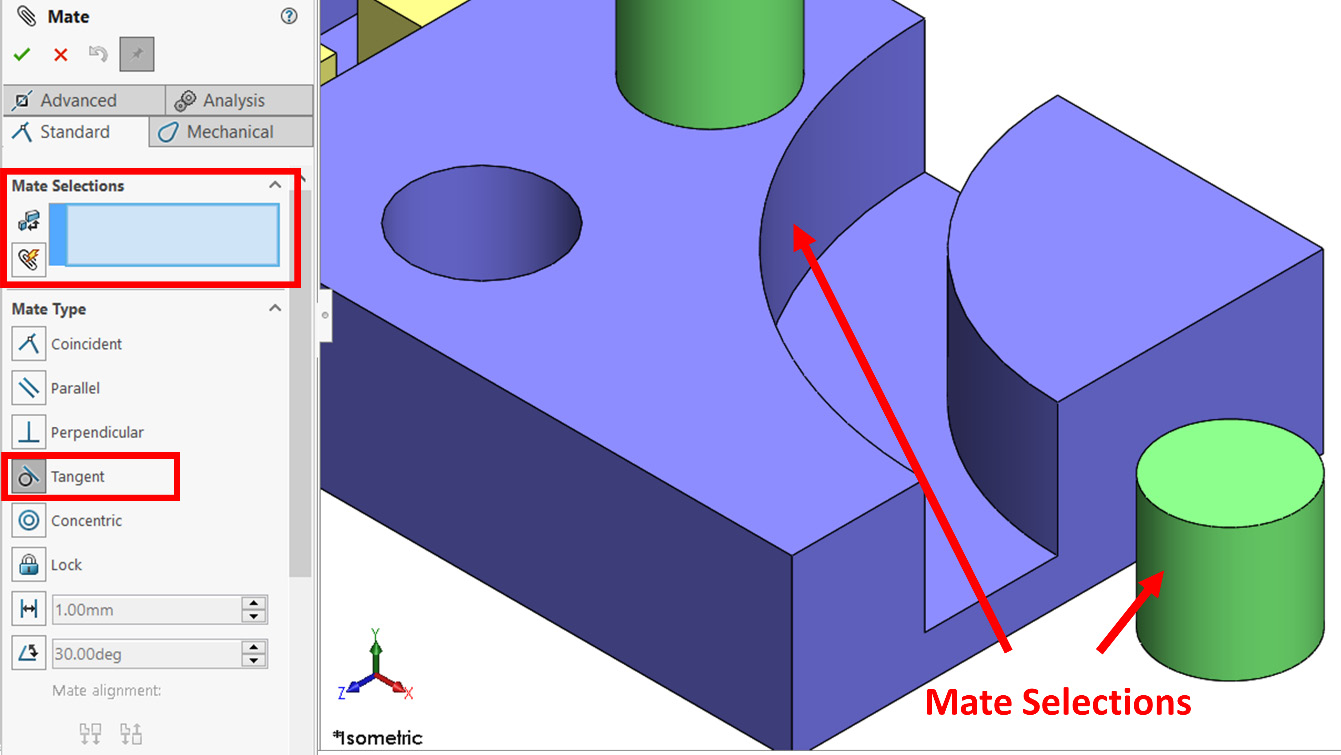
Figure 8.25 – The mate selection for the tangent mate
- Apply the mate by clicking on the green check mark.
After applying the mate, it's good practice is to drag the cylinder to see what effect it has. You will notice that the cylinder will move while keeping a tangent relation with the side we selected in the base part. In this example, we applied the tangent mate to two faces, but we can also apply the mate in the same way to two edges or an edge with a face.
This concludes this exercise on applying the tangent mate. Next, we will start applying the concentric mate.
Applying the concentric mate
In this section, we will apply the concentric mate to the cylinder and base that are highlighted in the initial drawing. To do this, follow these steps:
- Go to the Mate command and select the Concentric mate.
- Under Mate Selections, select the two faces shown in the following figure. Note the position of the cylinder will shift as the mate takes effect:
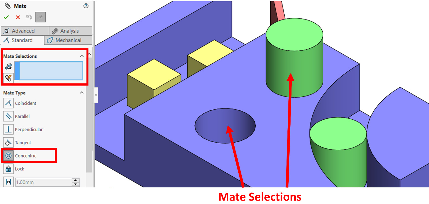
Figure 8.26 – The mate selection for the concentric mate
- Apply the mate by clicking on the green check mark.
After applying the mate, it's good practice to drag the cylinder to see what effect it has. You will notice that the cylinder will only move vertically, that is, up and down, so that the two rounded faces share the same center. In this example, we applied the concentric mate to two faces, but we can also apply the mate in the same way to two arc edges or an arc edge with an arc face.
This concludes this exercise on applying the concentric mate. Next, we will start examining the lock mate.
Applying the lock mate
In this section, we will apply the lock mate to the cubes that were highlighted in the initial drawing. To do this, follow these steps:
- Go to the Mate command and select the Lock mate.
- Under Mate Selections, select the two cubes shown in the following figure. Note that the position of the cubes will not change after we apply the lock mate:

Figure 8.27 – The mate selection for the lock mate
- Apply the mate by clicking on the green check mark.
After applying the mate, it's good practice to drag the cubes to see what effect it has. You will notice that as we move one cube, the other cube will move in the same way. This includes linear movements, as well as rotational movements. The lock mate can only be applied to whole parts.
This concludes applying the lock mate. At this point, we have covered how to apply all the non-value-oriented standard mates. Next, we will learn what fully defined means in the context of assemblies. We will also learn about other types of assembly definitions.
Under defining, fully defining, and over defining an assembly
When we finished the first assembly exercise, which is where we used the coincident and perpendicular mates, we noticed that all the parts are restrained from moving in any direction. Thus, the triangle will not move in any direction when it's dragged. This indicates that the assembly is now Fully Defined since both parts were fully restrained. This status is shown in the lower right-hand corner of the canvas, as shown in the following screenshot:

Figure 8.28 – The state of assembly is defined at the bottom of the canvas
However, in the second assembly exercise, where we looked at the parallel, tangent, concentric, and lock mates, we noticed that we could still drag the parts around, even after keeping certain movement constraints. When this happens, the status of the assembly will be Under Defined.
Similar to sketching, there are three different statuses and terms when it comes to defining an assembly. Those are under defined, fully defined, and over defined. However, the way we interpret them is slightly different in the context of assemblies. Here is a brief description of each status:
- Under Defined: There are one or more parts that are not fully constrained in terms of movement. In other words, if we click and hold that part and drag it, it will move.
- Fully Defined: In a fully defined assembly, all the parts are fully restrained. In other words, if we click and hold any of the parts and drag them, they will not move. Note that, in a fully defined assembly, we can apply more mates that serve the same purpose without over-defining the assembly. As such, even if the assembly is already fully defined, we can still apply more mates, that is, as long as they do not contradict each other. This aspect is different from defining sketches. In sketching, any relation that's added after fully defining a sketch will make the sketch over defined.
- Over Defined: In an over defined assembly, we have mates that contradict each other. Thus, we will need to delete or redefine some of the existing mates.
The indication at the bottom of the interface refers to the definition status of the whole assembly. Let's learn how we can find out the status of each individual part.
Finding the definition statuses of the parts
To find the definition status of each part in the assembly, we can look at the assembly design tree. At the beginning of each part's listing, SOLIDWORKS indicates what the statuses of the different parts are with symbols such as (f), (-), and (+). The meaning of each symbol is as follows:
- (f): Fixed
- (-): Under defined
- No symbol: Fully defined
- (+): Over defined
The following figure shows each of the symbols in the design tree:

Figure 8.29 – The parts' statuses as shown in the assembly design tree
Finding out the status of each part will help us when we need to define our assemblies. With this, we can decide which part needs more mates or which mate we should reconsider. However, in the context of assemblies, which definition status is better? We will discuss that question next.
Which assembly definition status is better?
When defining assemblies, we should avoid having an over defined assembly. However, there are certain advantages of having our assembly under defined or fully defined. Here are some scenarios for both cases:
- If the assembly has a moving part, a common practice will be to have the assembly under defined so that the desired movement is visible if we were to drag and move the part around. For example, if we assemble a windmill, we can choose to have the blades under defined to show how they move and how all the parts interact with each other during that movement.
- If all the parts in the assembly are fixed, a common practice will be to have the assembly fully defined. A common example of fully fixed assemblies is tables, which don't have any moving parts.
As we can see, keeping our assemblies fully defined or under defined has certain advantages. As designers or draftsmen, we will have to weigh up the advantages of each and adapt our own approach. Next, we will learn how to view and adjust active mates.
Viewing and adjusting active mates
In the assembly design tree, we will see a list of all the parts in the assembly, as well as the mates that have been applied to those parts. The lowest part of the assembly design tree shows the mates. We can expand this list to view all the mates that were involved in making the assembly. The following figure shows the mates we used to make the assembly we constructed earlier, that is, two Coincident mates and one Perpendicular mate:
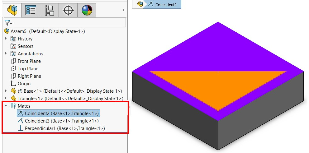
Figure 8.30 – Existing mates are listed in the assembly design tree
Tip
To see which elements of the parts are involved in the mates, we can click on the mate in the design tree. Then, the involved elements will be highlighted in the canvas, as shown in the preceding figure.
Now, we know how to view the active mates that we have in our assembly. Next, we will learn how to modify them.
Modifying existing mates
To modify a particular mate, we can right or left-click on the mate from the design tree. We will see the following menu. Here, we can choose to Edit, Delete, or Suppress the selected mate. Modifying mates follows the same procedure as modifying features:
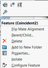
Figure 8.31 – A menu appears after right-clicking a mate, giving us different options
So far, we have learned how to use all the non-value-driven standard mates. We have also learned about the different statuses of assemblies, in addition to how to view and modify existing mates. Now, we can start learning about value-driven standard mates.
Understanding and applying value-driven standard mates
This section covers the standard mates that are defined by numerical values, that is, the distance and angle mates. We will learn about what do they do and how to apply them to an assembly. By the end of this section, we will be familiar with applying all the standard mates, which is our first step when it comes to working with SOLIDWORKS assembly tools.
Defining value-driven standard mates
Value-driven standard mates are those that depend on numerical values so that they can be set. They include two standard mates – distance and angle. Here is a brief definition of these two mates:
- Distance: This sets a certain fixed distance between two entities, such as edges and straight surfaces.
- Angle: This sets a certain fixed angle between two straight surfaces or edges.
Whenever we define one of these mates, we need to input a number that indicates the desired distance or angle. Now that we know what the distance and angle mates are, we can start applying them.
Applying the distance and angle mates
Here, we will apply the distance and angle mates to create the following assembly. You can download all the indicated parts from the download files that are linked to this chapter:
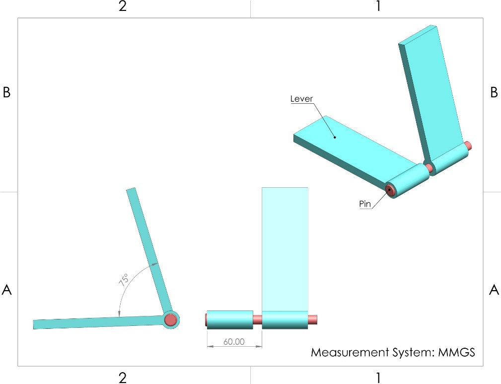
Figure 8.32 – The assembly we are making in this exercise
Note that, in the preceding drawing, the two levers are separated by a set distance of 60 mm. Also, the two levers have an angle of 75 degrees between them. This indicates that we can utilize the distance and angle relations to complete the assembly. To complete this assembly, we need to download the files that are attached to this chapter and open the Lever-Pin Assembly.SLDASM assembly file. The assembly will look as follows. Note that the assembly already has mates that are restraining them. However, we still need to add the distance and angle mates in order to achieve the assembly shown in the preceding figure. We can move the parts around in the assembly to find out how are they restrained:

Figure 8.33 – The initial status of the downloadable assembly for this exercise
Now that we have downloaded our parts, we can start applying the mates. We will start with the distance mate.
Applying the distance mate
To apply the distance mate, follow these steps:
- Select the Mate command. In Mate Selections, select the two slides.
- Select the Distance mate and select 60.00mm in the distance space.
- Apply the mate by clicking on the green check mark.
- Note the Flip dimension check box below the distance value. Checking this box will switch the distance from being toward the left to being toward the right and vice versa:

Figure 8.34 – The selection and the PropertyManager for the distance mate
After applying the mate, it's good practice to test its effect. We can do that by dragging the different parts to find out how the new mate is taking effect. In this case, we will notice that the levers can still rotate; however, they cannot move away from each other, that is, along the pin. Now, we will apply our next mate so that we can set the angle between the levers.
Applying the angle mate
To apply the angle mate, follow these steps:
- Select the Mate command. In Mate Selections, select the two slides.
- Select the standard mate Angle and input 75 degrees for the angle, as stated in the initial drawing.
- Apply the mate by clicking on the green check mark.
Similar to the distance mate, we will get a Flip dimension checkbox. This will flip the dimension that the angle is measured in. Try checking the box to see what effect this has on the assembly. Once checked, the output will be reflected in the preview on the canvas.
Note that, when applying mates, we may get a shortcut menu showing the various mates. We can use this menu in the same way we use the PropertyManager:

Figure 8.35 – The selection and the PropertyManager for the angle mate
Once we have applied the angle mate, the final shape will look as follows. Note that, if we drag any of the levers, the other lever will rotate with it while keeping the angle between them equal to 75 degrees. Also, note that the assembly is still under defined; however, we will keep it that way to show a simple simulation of how the different parts in the assembly move together:
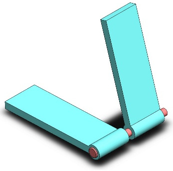
Figure 8.36 – The final status of the assembly
This concludes this exercise on the distance and angle mates. We have learned about the following topics:
- What the distance and angle mates are and what they do
- How to apply the distance and angle mates
At this point, we have covered all the standard mates that can be used in a SOLIDWORKS assembly. These allow us to model products that consist of different parts that interact with each other. Next, we will start looking at materials and mass properties within the context of an assembly.
Utilizing materials and mass properties for assemblies
When creating assemblies, we may need to determine the mass, volume, center of mass, and other related mass properties. This information is necessary, as it helps us understand our product from a physical perspective. As a result, they will help us develop or modify our product in case we ever want to adjust the mass, volume, and so on to meet a specific requirement. Similar to when working with parts, we can evaluate mass properties within the context of assemblies. In this section, we will learn about setting new coordinate systems, editing materials for the parts within the assembly, and how to evaluate the different mass properties for our assembly.
Setting a new coordinate system for an assembly
In many cases, we may need to reorient models ourselves directionally and find the center of mass from different locations. These are more common practices when we're working with assemblies compared to when we're working with parts. This is due to it being less intuitive to build upon the default coordinate system within the assemblies' environment. The previous chapter examined this topic in more detail.
To define a new coordinate system, we can follow the same procedure that we followed when we defined coordinate systems for parts. To access the command, we can go to the Assembly commands category and select Coordinate System under Reference Geometry, as highlighted in the following screenshot:

Figure 8.37 – The location of the new Coordinate System command
To define a new coordinate system, we have to define the origin, as well as the direction of the axes, similar to defining a coordinate system in parts. Introducing a new coordinate system in assemblies is a common practice when we're measuring coordinate-orientated mass properties such as the center of mass. Next, we will address how to edit materials within assemblies. Refer to Chapter 7, Materials and Mass Properties, for more information about coordinate systems. The procedure of setting and dealing with new coordinate systems is the same for both parts and assemblies.
Material edits in assemblies
There is no material assignment for the assembly. Instead, each part will carry its own material assignment. If the part was assigned a material when it was created, then this assignment will simply be transferred to the assembly. Within the assembly environment, we can still edit and assign materials to individual parts. We will learn how to do this here.
Assigning materials to parts in the assembly environment
We can assign a material to individual parts from the assembly environment. Follow these steps to do so:
- Decide which part you would like to assign/adjust to/for the material.
- Expand the part from the design tree. Then, select Edit Material, as shown in the following screenshot:

Figure 8.38 – We can edit parts' materials directly from the assembly
- Assign or adjust the assigned material as needed.
Important Note
Once we assign the material to the parts, it will be updated in the original part file since they are now linked.
- We can assign the same material to more than one part in one go by highlighting the parts, right-clicking, and then selecting the desired material, as shown in the following screenshot:

Figure 8.39 – We can edit the material for multiple parts at once
This concludes editing a part's material assignments within an assembly file. When editing materials in an assembly, take note of the following points:
- If we change the material within the assembly and save it, the part's material assignment will be updated as well. This is because the parts and the assembly file are connected.
- If we edit the material assignment for a repeated part (that is, we have more than one copy in the assembly), all the part's materials will be updated to match the new edit.
Now that we have materials assigned to our parts, we can start evaluating our mass properties.
Evaluating mass properties for assemblies
To evaluate the mass properties for an assembly, we can click on Mass Properties under the Evaluate commands category, as shown in the following screenshot:
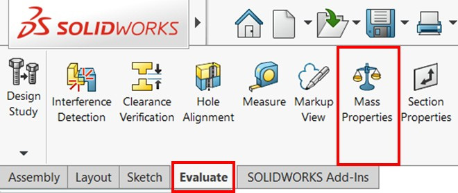
Figure 8.40 – The location of the Mass Properties command
This will show us the same information we received when we evaluated mass properties for parts. Refer to Chapter 7, Material and Mass Properties, for more information. The only difference is that the mass properties here will be a reflection on the whole assembly rather than on individual parts.
Note that the center of mass is calculated based on the position of the different parts that make up the assembly. If the assembly is under defined and we move the parts, the center of mass will change. This is in addition to all the other properties that are calculated based on the coordinate system's position, such as the moment of inertia. When moving the assembly, we may need to click on Recalculate in order to recalculate the mass properties, as shown in the following screenshot:
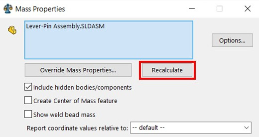
Figure 8.41 – The Recalculate command updates the values in the PropertyManager
Within assemblies, we can also calculate the mass properties of a specific part in relation to the assembly's coordinate system. To do this, we can select that part in the Mass Properties selection window, as highlighted in the following screenshot. This allows us to show the mass properties of a specific part within the assemblies' environment:

Figure 8.42 – We can find the mass properties of specific parts within the assembly environment
In this section, we have learned about mass properties in the context of assemblies. We have learned about setting new coordinate systems, adjusting the material assignments for our parts, and evaluating the mass properties for our assemblies.
Summary
In this chapter, we started working with assemblies. In SOLIDWORKS assemblies, we are able to put together more than one part to generate a more complex artifact. Most of the products we use in our everyday lives, such as phones, laptops, and cars, consist of multiple parts that have been put together; that is, they have been assembled. In this chapter, we learned about standard mates, which help us create links to different parts of the assembly. We learned what these mates do, how to apply them, and how to modify them. Then, we learned about materials and mass properties within the context of assemblies.
Now, we should be able to create more complex products that consist of more than one part. We should also be able to build simple static and dynamic interactions between those different parts. All of this brings us closer to designing more realistic products with SOLIDWORKS.
In the next chapter, we will start introducing 2D engineering drawings, which we will use to share our 3D models with individuals and organizations outside our circle or with those who don't have access to SOLIDWORKS. We will cover engineering drawings, why we need them, and how to interpret them.
Questions
Answer the following questions to test your knowledge of this chapter:
- What are the SOLIDWORKS assemblies?
- What are mates? What are the three different types of mates?
- What are standard mates?
- Download the parts linked to this question and assemble them to form the following drawing in Figure 8.43. The assembly should be fully defined:

Figure 8.43 – The drawing for question 4
- Using the assembly from the previous question, adjust the material for each part and define the coordinate system shown in the following drawing in Figure 8.44. Determine the mass in grams and the center of mass in mm according to the newly defined coordinate system:

Figure 8.44 – The drawing for question 5
- Download the parts linked to this question and assemble them to form the following drawing in Figure 8.45. The assembly should be fully defined:

Figure 8.45 – The drawing for question 6
- Using the assembly from the previous question, adjust the material for each part and define the coordinate system for the following drawing in Figure 8.46. Determine the mass in pounds and the center of mass in inches, according to the newly defined coordinate system:
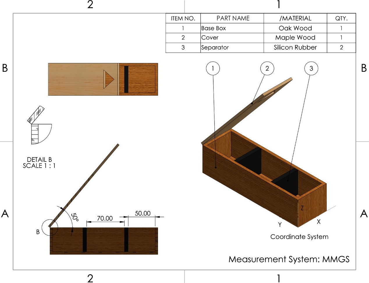
Figure 8.46 – The drawing for question 7
Important Note
The answers to the preceding questions can be found at the end of this book.