
5
Environment
When a player enters a game where the narrative is mostly driven by the environment, you need to ensure that most of the questions they may ask are answered. We will spend time in three major structures of environmental development – environmental design, blocking, and iteration. This should sound familiar from the character work we did previously in Chapter 4! Fortunately, there are differences involved in the environment regarding characters that we will cover quite extensively in this chapter. By the end of this chapter, you will have worked through enough environment questions to know how we designed our narrative, but also to work on your own. Let’s break down the topics so that you can get a glimpse of the chapter:
- Design – sketching, mood boards, and staging
- Blocking out – Mesh Blocking, Unity Terrain, Unity Probuilder
- Working through the iteration process
- Environmental design
The environment in a game is just as important as the character. We need to think deeply about our choices in terms of how the environment is in keeping with the theme and narrative of the gameplay. This is where we sit down with concept artists and designers to ask the difficult questions. Work through as much detail as possible to develop the purpose for the pieces of the environment.
Conceptualizing an environment needs to start somewhere. We started with sketching. We had an idea of what we wanted the environment to feel like from the beginning, so we decided to sketch up some quick concepts. After sketching, we put together some mood boards for a better definition of the style.
Once we are happy with the style and general concept, we then want to work in the following three stages to set the tone for the key points:
- Sketching
- Mood boards
- Staging
Let’s look at these stages in detail, starting with sketching.
Sketching
You may have some strong ideas on what you want the environment to look like. Just as in the other concept phases, you need to spend a large amount of time asking “why?”. This question will help define the context of your environment, so the experience fits together.
To perform sketching, you could employ several methods. Pen and paper work great for this to get sketches out quickly. Someone might have a great idea and draw on some napkins at a restaurant! If you’re in front of a computer, you can use Photoshop if you have a subscription, or try alternatives such as Krita or GIMP for free. Take some time to sketch out the architecture, broad shapes, and feeling. Each sketch will give you a closer look at what the final product could be. After each quick sketch, have a small conversation with yourself or the team to determine whether you need to ask more “why” questions in relation to the environment. The amount of sketching required will vary depending on how confident you are with conveying the emotion you want the player to experience. If you cannot fully describe the reasoning for each piece, then continue sketching and continue asking “why?”. Over time, the granularity will be enough to move on.
Below, in Figure 5.1, is a series of images, and I will briefly explain what they brought to the design of the environment for our vertical slice of the game. We really wanted to paint broad strokes of the environment type, meaning we’re developing without worrying about the subtle definitions. We were not looking for the architecture of the ruins or the flora of the environment. Initially, we were 100% certain of how we would put together a ruin in the mountains, but we needed to search through our sketches to figure out what felt right. We discovered that we wanted a remote mountainous region that was overgrown far enough that it almost felt cave-like in nature the entire time. This built up to a feeling that you weren’t actually on Earth, but on a planet similar enough to Earth to feel comfort in the shapes of nature.

Figure 5.1: Examples of sketches
While you are working your way through the tutorial, we wanted the last section when you reveal Myvari’s past to come with a drastic change to the feel of the area. This is initially shown in the bottom-right concept sketch in Figure 5.1. From this point, we knew we needed to push the architecture question and get the medium shapes defined.

Figure 5.2: Last puzzle area
By furthering the development of the last section, we knew we would need to have a stark contrast in terms of thematic visuals when the world shifted into Myvari’s realm. Looking at the differences in the images in the preceding Figure 5.2, the major difference is daytime versus nighttime. That’s a large change in itself, but we also wanted to make the ground and trees disappear while growing the architecture back to its old glory and bringing up reflective still water that reflects the stars in the sky, thereby really opening up this place as a new dimension.
After you get to a good point of sketching out your environment concepts, you want to then take what you’ve learned from the sketches and build out a mood board. Here, you can solidify references for the creation of your pieces in the future.
Mood boards
A mood board is a collage of images that draw out the style and mood of an area. There are hundreds of thousands of images on the internet that people have drawn, rendered, sketched, or even photographed that may be close enough to your style and tone that you can pull them together to inspire a little bit more of the experience you’re looking to provide to the player.
If you have definitive sketches, then this is your time to shine with mood boards. Take some time to search out similar features and feelings of architecture to make a collage of what the environment mood should feel like. This will define the palette of colors for you to work with on the modeling portion of this environment journey.
For our project, we had several major requirements. We wanted a mountainous jungle that brought an ancient magical fantasy civilization feeling to the game. Even if you were to search for “magical fantasy ancient jungle ruin,” there is a large chance that you wouldn’t be able to find exactly what you needed by way of reference. Instead, you break down the primary functions of each area and come up with a mood board. For our two examples, we will go over the cave and ruins mood boards.

Figure 5.3: Cave mood board example
In Figure 5.3 above, we focused on the primary function of the caves. What does it feel like to be small? What are the atmospheric tendencies for fog and lighting? This gives that sense of an alien environment even though you are still on Earth, perhaps in an unexplored area of our Earth.

Figure 5.4: Ruins mood board example
In Figure 5.4, we wanted to break down the function of ruins in a magical, fantastical civilization. What shapes would a nature-focused magical being want to strive for? How do the colors blend with one another?
Mood boards need to answer for mood and tone. You will know when you’ve completed your searching for mood when each of your key areas has a collage that best suits the mood that area needs to convey. In our case, we needed to feel out the caves versus the ruins. You’ll notice that both are drastically different in mood without even seeing all the finer details of the images.
Starting this after sketching makes sense if you can get questions answered through that step. However, if you find that sketching is only raising more questions overall, and muddling up the style that you want instead of defining it, then mood boards should come first. Searching for imagery of architecture tends to add a lot of clarity in terms of what is conceived.
Staging
After quickly sketching ideas and feelings to define the questions of “why,” you then built a mood board to further solidify the feeling of the environment. The next step is to take the previously defined shaping and mood and use it to push your narrative and mechanics into the stages of the game. The first location you bring your players to needs to answer a lot of questions rather quickly. Luckily, you took the time to answer as many questions as possible before this stage. You can now stage your narrative design with confidence. For our project, we knew we would need to explain as much of Myvari’s past as possible in each area you progress through.
When you’re building a stage, place yourself on the stage as best you can. Take your time going through the stage and ensure your primary questions were answered the way you expected in previous sections. Now, let’s try a new experiment: imagine the experience you’ve created through the lens of a new player. Try to feel what they might feel as a new player of 3D games. Are there enough hints to describe the experience for them? Then look at it from the point of view of an experienced player; would adding anything else take away from these power users?
This could take several iterations. Be patient with this step, and go through the stage to make sure you can explain the character’s assumed movements.
This is a good time to show someone else your designs and see what unprompted questions they have to offer you as well; it is amazing what we answer for ourselves without giving it much thought. Having a fresh set of eyes at each stage will reveal areas where a little more detail is required.
After some time, a picture of what you need at each stage will be clearer, and you can then take your stages into a blocking-out phase.
Blocking it out
Now that you have worked through as many of the concepts as you can, you should have a very strong idea of what would make your environment appropriate to the narrative and the characters. At this point, the next step would be to work through “blocking out” as much as possible; the point of blocking out is to put all the pieces together within Unity to fulfill the experience we worked so hard to define in the previous stages.
Now that you are aware of, and comfortable with, what goes into each portion of the entire level, you can speak to the mood and tone in each portion and become attuned to the general shaping from the concepts. To block a level out, we will use a few of the tools at our disposal; Unity Terrain, Basic Shapes, and Unity Probuilder will set us up to put down the basic environment pieces.
Unity terrain
Working with the Terrain tool in Unity is empowering. It’s very easy to get going and make a beautiful landscape quickly. To get started, let’s create a terrain entity. After creating the terrain entity, we will go through the settings, painting, and foliage that Unity provides us with as tools to create the terrain.
Creating a terrain
The first step to working with terrain is to create one. There are two main methods for doing so.
One way is to click on the GameObject menu, then 3D Object, and then Terrain, as shown in Figure 5.5.
Another way to start is by right-clicking an open area in the hierarchy and then selecting 3D Object, followed by Terrain.

Figure 5.5: Creating a terrain entity
Either of these options will create a terrain GameObject in the scene at the global coordinates of 0, 0, 0, sprawling positively in the x and z planes by 1,000 units, each by default. This value may not be what you need, so let’s go over the terrain settings.
Terrain settings
In our vertical slice, we will be using the default units as these are what we ended up needing for a sense of scale. This may not be the case for your game. One nice thing about the terrain is that it can be connected to neighboring terrain tiles easily.

Figure 5.6: Creating a neighboring terrain
The first option in the Terrain component is the Create Neighboring Terrain button. When this is selected, you will see an outline of the adjacent tiles, as seen in Figure 5.6. If you were to click on any of these squares, the terrain will create a new terrain asset that is linked to the primary terrain asset.
Now that you understand how the Terrain tool can connect to other terrains quite easily, you can now think about your terrain settings in terms of the size of each tile. It may be the case that your terrain only ever needs to be 500 units in length, and 200 in width. A common denominator of those is 100 units, so you could set your settings as in Figure 5.7 below.

Figure 5.7: Mesh resolution settings
If you plan on using grass or details on your terrain, make sure your terrain is square. If the width is different from the length, the Details Brush will have a hard time placing the billboards in an orderly way.
Clicking on the open squares will fill them in with another terrain tile. Clicking several may result in a terrain that looks similar to Figure 5.8.

Figure 5.8: Adding neighboring tiles
This gives you the freedom to add small offshoots that aren’t too large if you only need a little bit more terrain where you didn’t expect to need it.
In our case, we knew we only needed one block of 1000x1000, so we stuck with the default sizing. Our entire vertical slice will take place in a single scene with this default size for ease of setup.
Once you have your terrain scaled and set to the sizing that you will need, you may then need to add some detail to your terrain. Even though a stretching plane of infinite flatness is interesting in its own way, there is a good chance that your concept does have some hills or mountains in it. Let’s get to painting those in there.
Terrain painting
To get all those beautiful mountains and hills, we need to affect the terrain’s geometry. The Paint Terrain tool allows just this. You can find the tool button in the second available option in the Terrain Objects Inspector, which is shown in Figure 5.9.

Figure 5.9: Brush options
Your Brush option, which is located directly under the Tool options, is a dropdown that will change the functionality of the brush. To look at a list of brush options, click the dropdown as seen in Figure 5.10.

Figure 5.10: Painting options
We will go over their exact functions, but I suggest you take a bit of time to make a terrain you’re comfortable with by playing with the different brushes. There’s nothing like experience to get a feel for how they act on the terrain.
Raising or lowering the terrain
This tool will be your bread and butter while making a terrain. Depending on the size of your terrain and the scale that you need to make changes to the terrain, your brush size will be unique to your needs. Fortunately, there is a nice indicator, shown in Figure 5.11, to let you know the size and shape of your changes before you commit to the change and click.

Figure 5.11: Visualization of brush on different heights
When you select the Raising or Lowering Terrain brush, it shows a description box that explains if you click on the terrain, the brush will raise the terrain according to your brush shape, and if you hold down the Shift key while clicking the brush, this will lower the terrain according to your brush shape. If you attempt to lower your terrain on the flat parts, you’ll notice that it will not go below 0. This could be a problem if you’re planning on making indentions in the terrain to possibly put water in; there is a way to work around this, which we will go over later in the Setting the Height section.
Paint holes
After selecting the Paint Holes tool and taking a moment to click around with paint holes, this tool may not jump out as the most useful tool relating to terrain as it just erases the terrain. In addition to it just making a hole, it makes jagged edges, which don’t fit well with the rest of the terrain being nice and smooth!
But all is not lost! This tool is fantastic for you if you need to have a cave built as a terrain that is not designed to deal with concave shapes that would force an overlap in the terrain vertex.
It is common to design 3D meshes that encompass your needed cave system and then place it below the terrain and cut a hole in the terrain to access it.
We’ll cover 3D meshes in more detail in a later section, but here’s a rough and ready explanation: a 3D mesh is a set of vertices, creating polygons, that we use to visualize a 3D space.
The terrain is just a flat section being manipulated; it isn’t ground you can just dig into with a shovel. If you want a cave in the ground, you will need to make a hole, and then build a mesh below the terrain. This will leave some jagged edges, which you can see in Figure 5.12.

Figure 5.12: Example of paint holes before and after in the terrain
You can cover up those jagged edges with rocks, or other meshes that lead into the cave system.
Paint texture
Now you have most likely played enough that you have some hills, plateaus, and other various gray terrain-related material. You may want some color in your life, and luckily, there is an easy way to add some! You can search for a tileable texture online, or you can use one of the textures provided in the project to set this up.
When you first select the paint textures tool, there is nothing to paint as you need to create layers to paint with. Your terrain layers will be blank until you create one, so let’s do that first.

Figure 5.13: Editing terrain layers for painting
On the bottom right of the terrain layers, seen in Figure 5.13, there is a button labeled Edit Terrain Layers. If you select this, you can either create or add a layer. If you haven’t made a layer previously, you can click on the Add Layer option, but there will not be any options to fill that. Instead, let’s click on Create Layer. This will bring up a dialog box to select a texture. A tip here would be to name your texture something that you can search for easily, just in case you have a large number of textures to sift through. An example of this could be to name your terrain textures with a prefix of TT_, such as TT_Grass for grass. Then, when the dialog box is up, you can type TT in the search bar and it will only show the terrain textures. This trick can be used all over the project as there are search bars in most available options to select an asset to fill a role.
When you choose your texture, it will create a Terrain Layer asset that contains the texture you chose and some material options.
Figure 5.14 shows an example of a Terrain Layer.

Figure 5.14: Terrain Layer example
The primary property you will want to see here is the Tiling Settings. Depending on the scale of the game, you may need to increase or decrease the scaling to avoid seeing the tiles of the texture. If you look below at Figure 5.15, you can see where the texture tiles over and over. This looks bad from the camera’s current location, but in-game, it will be much closer, which allows us to prevent tiling from being as visible. The most interesting part of this is that it’s not connected to the terrain, so if you make a change to the layer asset, it will update the terrain right away. This makes it nice in terms of working quickly and getting an idea of what you want the terrain to look like while you can add normal maps and the metallic or smoothness elements later on.
The second thing that will happen is that the entire terrain will be painted with this texture. When you add another layer, you will then be able to utilize the same brush shapes and sizes to paint other layers onto the terrain.
Technically Interesting!
The way that terrain layers work is that Unity creates a texture map for each texture painted on the terrain. If you have four layers, each layer corresponds to the four channels in a texture: Red (R), Green (G), Blue (B), and Alpha (A). If you have five, the terrain gains a new texture, and it adds it to another R channel of another texture. Since this is the case, limit each tile to four textures for reasons of performance!
After you get the hang of working through the layers, it’s good to test small sections with your character to ensure that the scaling on the layer makes sense for the game scale itself, while keeping in mind that there will be other noisy factors to break up the texture tiling, such as grass, rocks, trees, or anything else that will be placed in your environment.

Figure 5.15: Testing brush strength when painting
If the character looks good at this point regarding the textures in respect to scale, let’s move on to the next option.
Setting the height
When working with the lower height tool, you may have noticed that it doesn’t go below the zero point. If you know you will be working below zero, which is very common, then the workflow to start is: before making any changes, set the height of the terrain to what might seem appropriate for the height you would need to go below zero in units.
Do you need to go 200 units down? If so, set the terrain GameObject to -200 in the position y, Figure 5.16 highlighted as step 1 in red. Then select the Paint Terrain option while also selecting the Set Height dropdown as shown in Figure 5.16 marked as 2 in red. After that, the value will be -200, so set it to 0, then flatten it with the Flatten button in Figure 5.16 marked as red 3.

Figure 5.16: Setting Height to allow for lower than world 0
This will set the terrain visually back to 0, 0, 0 as its location and keep the offset in place so that you can lower the terrain below that mark. This is very effective for making swamps, caverns, and rivers.
Smoothing the height
Smoothing is a straightforward tool. Sometimes, you may need to just smooth out the terrain slightly as the noise placed on it could have gotten out of hand, or you needed to smooth a path for the player character to walk on to help guide the character’s movement.
As a simple example, look at Figure 5.17 below.
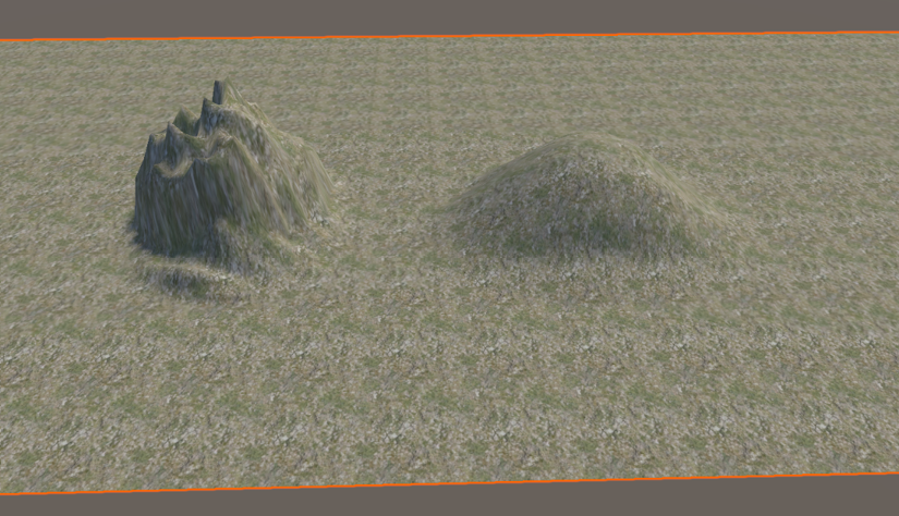
Figure 5.17: Smoothed terrain
This is a somewhat extreme version of smoothing, but both looked the same prior to smoothing. You can also apply smoothing with a noisy brush to smooth in a non-uniform way to give a look of erosion to the terrain.
Stamping the terrain
The stamp tool is used as a 3D stamp! If you need a specific terrain feature, you author a height map to stamp the terrain with. You add the heightmap to the brushes and then you use it on the terrain.
One of the main use cases for this tool is that you can get pre-authored heightmaps that have already been proven to look good on terrain. If you want to find nice mountains and hills, you can search for them in the asset store and there will be examples for you to start with. This will speed up the process drastically. It may not be what you need exactly, but every step is progress.
Painting trees
When you select the Paint Trees tool, it will have the options as seen in Figure 5.18.

Figure 5.18: Paint Trees terrain mode
To get started, click the Edit Trees button, and add trees. You’ll be able to add whatever mesh you like even if it isn’t a tree! There is a warning, seen in Figure 5.19, that pops up if your mesh isn’t built correctly for the tree placement on the terrain. It looks like this:

Figure 5.19: Defined Tree and LOD group warning
Luckily, there is a free asset on the asset store by SpeedTree that you can download to get a great example of how to properly put together a tree for the Paint Tree tool.
Painting details
Lastly, we have painting details. Here, you can either add a detail texture, which will get rendered on a quad, or you can use a detail mesh to create your own mesh. Here is an example of a simple grass texture being used and painted on a flat terrain:

Figure 5.20: Grass as a detail
Painting details such as grass helps to break up the ground texture, shown above in Figure 5.20. These items can also be affected by wind zones, which are another component that could be added to the terrain object. If you wish to push this further, please investigate Chapter 10, Sound Effects, where we will add ambient sounds and other small polishing details, and Chapter 12, Finishing Touches, to breathe life into the terrain.
3D geometry
Now that you’ve set up your terrain, you will need to augment the terrain for architecture or building out a cave system. You will need to utilize a 3D Digital Content Creation (3D DCC) tool to build out the meshes for your environment. There is another option to build out the block-out phase, which is Unity’s ProBuilder. In our case, we will be using both ProBuilder as well as creating our own geometry for custom shape definition to denote specific architectural portions of the environment.
Let’s dig into what ProBuilder and custom meshes mean for your environment blockout.

Figure 5.21: Examples of Unity’s ProBuilder and custom meshes from our 3D DCC
ProBuilder
From the Unity documentation, ProBuilder is defined as follows:
You can build, edit, and texture custom geometry in Unity with the actions and tools available in the ProBuilder package. You can also use ProBuilder to help with in-scene level design, prototyping, collision meshes, and play-testing.
ProBuilder can quickly set up your scene with collidable surfaces to quickly visualize your environment with ease. To get started with the tool, we will go over some starting steps where you can create your own scene for ease of familiarity. We will go over the installation, creation of the ProBuilder shapes, editing, and then some commonly used tools in ProBuilder.
Installing ProBuilder
To install ProBuilder, open the package manager and go to the Unity Registry, shown in Figure 5.22. Select ProBuilder, and then download and install it.

Figure 5.22: Unity Registry Package Manager
After you install it, you will need to access the Tools menu to open the ProBuilder Window, as seen in Figure 5.23 below.

Figure 5.23: Probuilder Window path
This will open a floating window with a lot of options. To get started, let’s dock the window to the left of the scene window. This is a personal preference, but we like to be able to work with ProBuilder and still be able to select the items in the hierarchy with ease. Now that we’re set up, let’s go over the colors in the menu.

Figure 5.24: Probuilder Object mode
In Figure 5.24 above, we are currently looking at the Object mode of ProBuilder and there are only three colors available in this menu, but there is a fourth color, which we will go over in the Common ProBuilder Tools section. The three colors we currently see are used in specific ways to help work through all the options easily. They work like this:
- Orange: Object and windowed tools
- Blue: Selection-based functions
- Green: Mesh editing tools that affect the entire shape that’s selected
Now that we have an idea of what these are for, let’s get to building our first shape.
Creation of ProBuilder shapes
Open a new scene and let’s create a new shape from the ProBuilder menu. This will reveal a small window in the bottom right of the Scene viewport, seen in Figure 5.23. You will have several options in terms of the type of shape you want to create. We’re going to select the Plane option so that we can have something for our shapes to attach to. You can find this located in Figure 5.25 below.

Figure 5.25: Create Shape submenu
After you select the plane, left-click and drag in the scene to create a plane. Don’t worry about the size of it for the time being; just create the plane and we will make edits next.
Now, in the hierarchy, if the plane isn’t selected, go ahead and select it. In the Inspector, let’s set the transform to 0, 0, 0 so it is centered in our scene at 0. Then, go down to the ProBuilder script and change the size to 80, 0, 80. This will give us a sufficient size to play with whatever shape we want to in the scene. The Inspector should look similar to Figure 5.26 when you’ve finished these steps.

Figure 5.26: Position and shape properties Inspector window
After the plane is created, let’s make a cube. Create a new shape and choose a cube shape in the interactive tool in the scene. Left-click and drag to make the base whatever shape you wish. Release the left-click and then you will be able to drag up to give the cube its height. Finish making the cube by clicking again at the height you’d like it to be for now. Once you have that, let’s add one more shape, stairs, to the cube. The goal is to make a set of stairs that would allow a character to be able to climb up to the top of your cube. If your stairs turn out strange, don’t worry; just delete them and try again until you get it close enough. Don’t worry about getting it perfect; we will go into the editing of shapes next.
Editing the shapes
It’s possible that when you made your stairs, they turned out something like Figure 5.27 below.

Figure 5.27: Stair placement problem
Not that you wanted that, but it just turned out this way. Luckily, the editing portion of ProBuilder is very strong. If you hover your mouse over the face of the stairs, there should be a blue arrow facing up, down, left, and right respective to the center square of that face, as shown in the preceding figure.
If you do not have this when you hover over, this means that you may have deselected the stairs and ProBuilder thinks you don’t need to edit the base shape anymore. This can easily be fixed by selecting another item in the scene and then reselecting the stairs. Then, in the Inspector and the ProBuilder script, there is an Edit Shape button. Selecting this will give you access to the basic editing features again.
Clicking and dragging the middle square will allow you to move that face of the shape. Clicking the arrow will reorient the entire shape. This is very useful for our stairs. The yellow arrow highlighted in Figure 5.27 will orient the shape to the back of the stairs, which will make the topmost stair be against the cube. This is what we wanted, so we selected it and then used the middle squares to redefine the shape to how we thought the stairs would look the best in this example.
Even though these tools are quite powerful for blocking out, we can go a bit further and talk about the component manipulation tools.
Common ProBuilder tools
We’ve created some shapes and edited their overall state and shape to get the basic building blocks of a structure. To get some more medium shapes, we need to work on the components of these shapes. Looking back to Chapter 1, A Primer to the Third Dimension, the component structure of 3D objects are the vertex, edge, and face. These are denoted by a small icon shape at the top of the scene viewport when ProBuilder is installed, seen in Figure 5.28.

Figure 5.28: Component Selection tool
From the left to the right, we have Object, Vertices, Edges, and then finally, the Faces selection. If you select one of them, you will then be able to select those component types of the ProBuilder shape that you have selected in the hierarchy. This will also change the available options in the ProBuilder toolset. Compare this to Figure 5.29, with the options from Figure 5.24, and you will see we added red to our available options and the other colors have had changes in their options as well.

Figure 5.29: Component Menu options
The red options that are available are per component. In this case, we’ve selected the vertices manipulator; the options for component tools relate to the vertices. The same would be true regarding the selection of edges or faces. Take some time and cycle through them to see the available options for each component. When you get to faces, let’s stop for a moment as there is one tool that is used very often – the Extrude tool.
Extruding a face will duplicate the vertices and keep the faces connected to extrude your geometry out from the selected faces. This is an incredibly powerful and fast tool to build many shapes or add detail. We will perform two versions of this to give an idea of how this works. These are extrusions and insets.
To make an extrusion, select the face component option at the top of the scene window, and then select a face of the box we have next to the stairs. Press the W key to get to the transform tool. While holding the Shift key, left-click and drag the arrow facing up. You should get an extrusion going up! It should look like Figure 5.30 below.
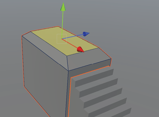
Figure 5.30: Extrude tool
The extrusion is the top box that was pulled out from the selected face. You can now manipulate the face to make it into any shape you would like. We aren’t big fans of all 90-degree angles, so we pressed R and scaled it in from the middle to give it a little bit of personality.
Now, insets are interesting as they are a specific set of extrusion to bring the face back into the current shape. This is great for adding quick details. How we are going to perform this is by selecting the face that is on the side of the box facing the camera, hitting the letter R for the scale tool, and, while holding down the Shift key, left-clicking the gray box in the center to scale from all sides. After doing that, we will hit the W key to get back to the transform tool, and, while holding the shift key down again, pull the blue arrow to bring in the inset. Figure 5.31 below includes both steps for creating the inset on the same face as suggested.

Figure 5.31: Inset example
Play around with the tools for each of the components. You will find that they are there to help speed up the workflow so you can get to blocking out as much as possible, as quickly as possible. There may be a time when you know a specific shape is needed, but you cannot achieve it with ProBuilder tools. In this case, you may need to get into an external tool such as Autodesk Maya or Blender to achieve the look that is needed. We tend to call these objects premade shapes.
Premade basic shapes
If you have a good idea of the shaping that you need for your environment, you may already have set up environment pieces that link together at the right scale. ProBuilder is very good with basic shapes, but you may need some architecture that is specific to your game. If you have the availability, it may be easier to just create that and use the mesh instead of using ProBuilder.
In some cases, you may have shapes already created previously that would work just as well as ProBuilder, and all you would need to do is import them into Unity and place them where you’d like. This could prove useful for speeding up the block-out phase.
In our scenes, you will see that we use all three (Terrain, ProBuilder, and premade shapes) to put together a cohesive integrated scene. This is primarily due to the speed at which our artist could create certain models in a DCC versus ProBuilder. Sometimes, however, a basic block that’s been extruded is all we need to make the scene make sense for blocking in.
Iteration
The process of iteration is looping through portions of the work to get to a refined enough state to move on to other parts of the game. We will follow Figure 5.32 below as a simple track. This is a high level of the process and after you go through it a few times, you will create more steps for yourself and your team to follow. For now, let’s work through the highlights.

Figure 5.32: Iteration process
We’ve already gone through several blocks in the process above, such as conceiving and blocking. We just need to go through refining and testing. Refining is the action you take to get as close to answering an action as you can on a granular level. An example of this in relation to our project is asking how close to Myvari’s culture each puzzle is. We needed to refine this from blocks to architecture and ensure the puzzle itself makes sense to the style in mechanics, which we will go over in Chapter 6, Interactions and Mechanics. If the granular level answer makes sense, extend your scope to testing. In testing, you will take a broad stroke of the game. If you can, test the feel of the game by walking around and see whether there are any other questions on a high level that may have emerged through the refinement process.
This is where time can easily go out the window. You will need to have a firm grasp of what “good enough” means for your game. One of the hardest parts of game development is where you must realize that shipping the game is more important than making everything perfect. Be vigilant in your cause to release and get it looking and feeling good enough, and then move on. You have a lot more to get through!
We’ve only talked about the block-out phase in this environment chapter. This is because of how important it is to block it out and take some time to feel it through play. Fail fast and make changes according to your feedback from either you playing the game yourself or one of your friends playing it. After you get to the point where you think each section is good enough, then you can start importing final meshes that are in the shape or in the place that you’ve decided was the correct space. Once this is complete, make another run with the game as you may see changes from the final meshes coming in that weren’t apparent previously with the block-out meshes.
Moving around the level and throughout multiple parts of the scene, look carefully at cohesion. Once moving around the level feels good, then you need to push more into the mechanics of the game itself and get into more development, beyond just the art. There will be more questions that pop up in the future. Taking these iterations seriously first will lay a strong foundation to work through when you get into the next portions of your game.
Summary
We’ve gone through a large number of Unity tools in this chapter. Take your time to work through the Terrain tools and the ProBuilder tools to get a good understanding of how they work.
From this chapter, you gained knowledge of multiple tools to build out an environment. We took time to explain how to iterate through this whole process to gain a strong sense of structure in your environment. You learned how to start with design thinking to build out a concept. Then, you took the concept and started staging each section of the concept, before finally putting the environment together and iterating on it to get a clear view holistically.
Next up, we will go over the mechanics of your game to fit it within your environment. Keep this chapter in mind when placing the interactions for the mechanics as there will be more iteration throughout the development process.