
Chapter 4: Extending the Cloud to the Edge
In the material leading up to this chapter, all of the development steps were performed on your device locally. Local development is useful for learning the tools and rapid prototyping but isn't representative of how you would typically operate a production device. In this chapter, you will treat your hub device as if it were actually deployed in the field and learn how to remotely interact with it using the cloud as a deployment engine.
Instead of authoring components on the device, you will learn how to use Amazon Web Services (AWS) IoT Greengrass to synchronize cloud resources, such as code, files, and machine learning (ML) models, to the edge and update devices via deployments. The tools, patterns, and skills you will learn in this chapter are important to your goals of extending the cloud to the edge and practicing how to manage an edge ML solution. You will connect a new client device to your hub device and learn how to bridge connectivity to a cloud solution. Finally, you will deploy your first real ML model to the edge. By the end of this chapter, you will be as familiar with pushing components and resources out to edge devices as you would for a production fleet.
In this chapter, we're going to cover the following main topics:
- Creating and deploying remotely
- Storing logs in the cloud
- Synchronizing the state between the edge and the cloud
- Deploying your first ML model
Technical requirements
To complete the hands-on steps for this chapter, you should have a hub device as defined by the hardware and software requirements in the Hands-on prerequisites section of Chapter 1, Introduction to the Data-Driven Edge with Machine Learning, and that device should be loaded with AWS IoT Greengrass core software, as defined by the steps from Chapter 2, Foundations of Edge Workloads. You will also need access to your command-and-control (C2) system, typically your PC or a laptop that has a web browser, and access to the AWS management console.
The resources provided to you for the steps in this chapter are available in the GitHub repository under the chapter4 folder, at https://github.com/PacktPublishing/Intelligent-Workloads-at-the-Edge/tree/main/chapter4.
Creating and deploying remotely
Up until now, you have been interacting with your IoT Greengrass solution directly on the hub device using the IoT Greengrass command-line interface (CLI). Going forward, you will learn how to interact with your IoT Greengrass device from your C2 system (laptop or workstation) through the use of the AWS cloud. The CLI and local development lifecycle are great for learning the basics of IoT Greengrass and rapid iteration on component development. The best practice for production solutions is not to deploy the Greengrass CLI component to your devices and install new components locally, so next, you will learn how to package your components, store them in AWS, and complete remote deployments to your hub device.
Loading resources from the cloud
Components can include any number of artifacts defined by the recipe file, and those artifacts must be stored somewhere the Greengrass device can access them. Artifacts can be static resources of any kind: binary data such as images or text, application code such as Python source code or compiled Java ARchive files (JARs), containerized code such as a Docker container, and anything else that your component needs a copy of to work, the keywords here being static and copy. Artifacts are resources that your device uses that are copies that every other device deploying that component uses. They are also not intended to change on the device after deployment.
The other kind of resource that components use is dynamic resources. A dynamic resource gets loaded as a configuration specific to the device or something that gets consumed at runtime. Dynamic resources may be ephemeral in that they exist only as long as the device is online or a component is running. Some examples of dynamic resources are secrets to reference in your code such as an application programming interface (API) key, behavioral settings to include based on the device's identifier (ID) or other metadata, and communication channels between any leaf devices (those at terminal points in the solution, such as Home Base Solutions (HBS) appliance monitoring kits) and the Greengrass device (such as the HBS hub device), software components, and the cloud.
In the first hands-on section of this chapter, you will get familiar with how a recipe defines static resources as artifacts and perform your first remote deployment with a custom component. Later sections of this chapter will introduce implementations for dynamic resources.
Packaging your components for remote deployment
The main difference between local and remote deployment on IoT Greengrass is where the component resources come from. In your local development lifecycle, you were authoring files on the hub device itself and pointing to folders containing recipe and artifact files. For remote deployment, you must store your files in the AWS cloud using Amazon Simple Storage Service (Amazon S3) and update your recipes to point at S3 object locations. In the next steps, you will update the permissions model of your IoT Greengrass device to be able to read objects from S3, package up a component to S3 using the AWS CLI, and create a new remote deployment to your hub device.
Updating IoT Greengrass permissions
In your initial setup of IoT Greengrass on your hub device, a new role was created in the AWS Identity and Access Management (AWS IAM) service that the IoT Greengrass core service uses to get authorization to interact with any AWS services. In AWS, the AWS IAM service is where all users, groups, policies, and roles are defined that grant access to resources and APIs in your account.
A user is an IAM resource that serves as identification—for example, you as the internet of things (IoT) architect getting permissions to use APIs, or the idtgg user we defined for initially provisioning your hub device in AWS. A policy documents the sets of allowed and denied permissions that we attach to identities. A role is a façade of permissions that authorized users can assume to gain those specified permissions. A user gets permissions granted in one of three ways. Policies can be directly attached to the user or inherited from a group to which they belong. Policies can also be attached to roles that users assume for temporary sessions, letting the user perform specific session-based tasks following the principle of least privilege (POLP). By using roles, we can define abstract sets of permissions that users can gain for the completion of specific tasks to follow the best practice of limiting permission scope. Here is a simple illustration of the relationship between a user (one type of security principal), a role, a policy, and the permissions granted to the user by assuming the role:

Figure 4.1 – An IAM user gets temporary permissions and credentials from a role
A real-world analogy for users, policies, and roles is when your friend temporarily gives you their house key while they are away so that you can water their plants or feed their cat. You can think of the role as Someone Who Can Enter My House, and the house key is the policy that grants access to their house. By trusting you with the key, your friend is granting you, the user, a temporary role to enter their home. When your task is complete and your friend returns home, you relinquish the key and thus end your session in that role. In the digital world, you as the user have your own key (such as a public certificate) that identifies you. The role and its policy grant your key temporary permission to access the resource instead of giving you the only key!
The installation process of IoT Greengrass created a new role named GreengrassV2TokenExchangeRole and attached to it a policy named GreengrassV2TokenExchangeRoleAccess that grants access to the APIs for interacting with the AWS IoT Core service and for writing logs to Amazon CloudWatch. By default, and as a best security practice, this policy does not include access to objects stored in S3. It is up to you as the solution developer to describe which S3 objects your devices should be able to access and add that configuration to the role as a new policy.
Note
For the rest of this chapter, steps with AWS CLI commands and simple filesystem management commands (such as the creation of new directories or files) will be written in Unix format for macOS and Linux systems. To get help using commands in AWS CLI where there are distinct differences for Windows, such as referencing local files as input, please refer to the AWS CLI documentation at https://docs.aws.amazon.com/cli/latest/userguide/.
In the next steps, you will use the AWS CLI to create a new bucket in S3, a new policy that grants read permissions to objects in that S3 bucket, and then attach the new policy to the role used by IoT Greengrass devices. Proceed as follows:
- From your C2 system, open the terminal (or run cmd.exe/PowerShell on Windows).
- Use the AWS CLI to print out your 12-digit account ID by running the following command: aws sts get-caller-identity --query 'Account' (the output should look like this: 012345678912).
- Create a new S3 bucket in your account. S3 bucket names share a global namespace in AWS. A good practice for naming buckets is to include your AWS account ID as a unique string. If a bucket name is already taken, you can add unique text (such as your initials) to the name until you find one that is not taken. Use the account ID from the previous step and replace the 12-digit account ID placeholder. Be sure to update the region if you're not using the default of us-west-2. The output should look like this: aws s3 mb s3://012345678912-hbs-components --region us-west-2.
- From here on out, we will refer to this bucket name as REPLACEME_HBS_COMPONENTS_BUCKET. When you see a command or text in a file with the REPLACEME_HBS_COMPONENTS_BUCKET placeholder, you need to replace it with the name of your bucket, like this: 012345678912-hbs-components.
- Next, you will create a local file to store the content of the new policy that grants read access to the objects in your new bucket. You can find a template of this file in the GitHub repository for this book at the chapter4/greengrass_read_s3.json path and update the REPLACEME_HBS_COMPONENTS_BUCKET placeholder. If you're creating the file yourself, name it greengrass_read_s3.json and add the following content (remembering to replace the placeholder!):
greengrass_read_s3.json
{
"Version": "2012-10-17",
"Statement": [
{
"Effect": "Allow",
"Action": [
"s3:GetObject"
],
"Resource": "arn:aws:s3:::REPLACEME_HBS_COMPONENTS_BUCKET/*"
}
]
}
- Create a new policy in IAM with this document as its source: aws iam create-policy --policy-name GreengrassV2ReadComponentArtifacts --policy-document file://greengrass_read_s3.json.
- Add the policy to the IAM role used by IoT Greengrass. Replace the value of the --policy-arn argument with the arn value output from the previous command, as follows: aws iam attach-role-policy --role-name GreengrassV2TokenExchangeRole --policy-arn arn:aws:iam::012345678912:policy/ GreengrassV2ReadComponentArtifacts.
Now, your IoT Greengrass devices, such as the HBS hub device, can read component files that are stored in your S3 bucket. Let's cover one more element of how the security model works between the hub device and an AWS resource.
Earlier, we described the relationship in AWS IAM between a user, a role, and a policy. Your devices don't have any identity as a user in AWS IAM, so how do they assume the role? The answer is a feature of AWS IoT Core called the Credentials Provider service. Your devices do have an identity provisioned in AWS IoT Core using an X.509 private key and public certificate. The credentials provider service is a means for connected devices to present their registered public certificates in exchange for temporary AWS credentials that have permissions granted through an IAM role.
Here is a sequence diagram showing the path for your HBS hub device to get permissions and ultimately read an object in S3:
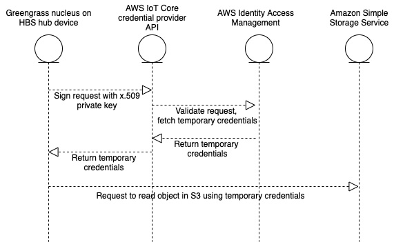
Figure 4.2 – Sequence diagram to fetch temporary credentials
As your edge solution adds features that interact with more AWS services, you must add permissions to those services using the same process you just completed. The same is true for your custom components that interact with AWS since all components get permissions through the IAM role of your device's configuration. As the number of distinct edge solutions in your account grows, the best practice is to create distinct IAM roles per distinct group of devices. For example, each HBS hub will have the same solution and can share a common role that defines permissions to access AWS. For the next project at HBS using IoT Greengrass, instead of adding more permissions to the same IAM role, it is best to create a new role for devices of that project.
Note
There is a regional quota for the number of roles you can define for your devices in AWS IoT. As of this writing, the quota is 100. This means you don't want to create a unique role per Greengrass device, as you will quickly reach the maximum quota as you scale. A best practice for a production solution on AWS is to use one AWS account per production solution, such as maintaining the fleets of hub devices at HBS. A different product line may be deployed in a separate AWS account, thus expanding the total number of roles to use.
With the new permissions added, you can move on to the next section, where you will package up a new component and register it in the cloud service of IoT Greengrass.
Registering a component in IoT Greengrass
In order to remotely deploy a component to your hub device, you must first register the component in the cloud service of IoT Greengrass. You will provide a recipe file as input to an API, just like you did when using the local IoT Greengrass CLI on your device. The recipe file will define the location of all artifacts used by the component. These artifacts must be uploaded to an S3 bucket such as the one created in the previous step. When IoT Greengrass processes your recipe file, it will register a new component in your account that can then be referenced in a future deployment to any of your devices.
The first step in registering a component is to add your artifact files to the S3 bucket. Only then will you know the addresses of those files in S3 to be able to update a recipe that can reference them. In this section, you will upload a ZIP archive as an artifact, replace the path to the artifact in the recipe file, then register the component in your account using the AWS software development kit (SDK), as follows:
- From the book's GitHub repository, change directory to chapter 4 by running the following command: cd chapter4.
- Use the AWS SDK to upload the artifact file by running the following command: aws s3 cp artifacts/com.hbs.hub.HelloWithConfig/1.0.0/archive.zip s3://REPLACEME_HBS_COMPONENTS_BUCKET/artifacts/com.hbs.hub.HelloWithConfig/1.0.0/archive.zip.
- Edit the recipes/com.hbs.hub.HelloWithConfig-1.0.0.json file and replace the value of the Uniform Resource Identifier (URI) key with the path to your artifact in S3 (the last argument in the previous step). After filling it in, it should look something like this:
"Artifacts": [
{
"URI": "s3://012345678912-hbs-components/artifacts/com.hbs.hub.HelloWithConfig/1.0.0/archive.zip",
"Unarchive": "ZIP",
- Now that your artifact is in S3 and your recipe file is updated, you can use the AWS SDK to register your new component in the cloud service of IoT Greengrass. In the response will be the Amazon Resource Name (ARN) of your component that you will use for future steps. Run the following command: aws greengrassv2 create-component-version --inline-recipe fileb://recipes/com.hbs.hub.HelloWithConfig-1.0.0.json.
- The preceding command returns a status such as componentState=REQUESTED to signal that IoT Greengrass is taking steps to register your new component. To check on the status of your component registration, run the following command (replacing the --arn argument with the one found in the output from the previous step): aws greengrassv2 describe-component --arn arn:aws:greengrass:us-west-2:012345678912:components:com.hbs.hub.HelloWithConfig:versions:1.0.0.
When the component is registered in the service, you will see a response to this command with the componentState value now showing as DEPLOYABLE. This means the component is now ready for inclusion in a new deployment to a device. Before moving on to the deployment, let's take a look at the recipe file now stored by IoT Greengrass with the following command (replace the --arn argument with your component's ARN from previous steps): aws greengrassv2 get-component --arn arn:aws:greengrass:us-west-2: 012345678912:components:com.hbs.hub.HelloWithConfig:versions:1.0.0 --query "recipe" --output text | base64 --decode. You may notice the recipe file doesn't look exactly like the one you sent to IoT Greengrass. Here's what the Artifacts object looks like now:
"Artifacts":[{"Uri":"s3://012345678912-hbs-components/artifacts/com.hbs.hub.HelloWithConfig/1.0.0/archive.zip","Digest":"wvcSArajPd+Ug3xCdt0P1J74/I7QA2UbuRJeF5ZJ7ks=","Algorithm":"SHA-256","Unarchive":"ZIP","Permission":{"Read":"OWNER","Execute":"OWNER"}}]
What's new here are the Digest and Algorithm keys. This is a security feature of IoT Greengrass. When your recipe is registered as a component in the service, IoT Greengrass computes a SHA-256 hash of each artifact file referenced by the recipe. The purpose is to ensure that the artifacts eventually downloaded by any IoT Greengrass devices have not been modified before use. This also means you cannot alter an artifact file stored on S3 after registering the component. To update any artifact requires you to register a new version of the component and deploy the new component version.
Two more deltas between this component and components developed locally in previous chapters are the use of the decompressed path and artifact permissions. Here is a snapshot of the key differences in this recipe file:
"Lifecycle": {
"Run": "cd {artifacts:decompressedPath}/archive && ./hello.sh"
},
"Artifacts": [
{
"URI": "s3://REPLACEME_HBS_COMPONENTS_BUCKET/artifacts/com.hbs.hub.HelloWithConfig/1.0.0/archive.zip",
"Unarchive": "ZIP",
"Permission": {
"Execute": "OWNER"
In the Lifecycle object, you can see the run script that makes reference to the artifacts:decompressedPath variable. This variable points to the directory where Greengrass automatically unarchives your archived artifacts. Files are unpacked to a subdirectory with the same name as the archive—in this case, archive/. We know our hello.sh script will reference the adjacent config.txt file from the same archive. We must tell the run script to change directory to the decompressed path and then run the script in order to find the config.txt file in the correct directory context.
The best practice for your artifacts is to consume them from the artifacts directory, as downloaded or unpacked by IoT Greengrass, and to use the component's work directory, available in the recipe as work:path, for files to which your component will write data. The work directory is the default context for any lifecycle script, and that is why we include a change directory command before running our script artifact.
The other new inclusion is the Permission object, where you can see we are setting an Execute property to the OWNER value. By default, artifacts and files from unpacked artifacts have a filesystem permission of Read for the component's owner (such as the default ggc_user). This means a script file in our archive.zip file would not be executable without a change to the file's permissions. Using the Permission object for any artifact, we can set the Read and Execute filesystem permissions to any of NONE, OWNER, or ALL (all system users). This is also related to why artifacts are write-protected. Artifacts are intended to be read-only resources consumed by the component or executable files that should not be changed without a revision to the component's definition.
In the next section, you will deploy your newly registered component to your device.
Remotely deploying a component
With your component now available in the IoT Greengrass service, it's time to start a remote deployment from your C2 system to your HBS hub device using the AWS CLI. This kind of deployment from a remote system using the IoT Greengrass cloud service is the standard way by which you will deploy updates to your devices. It may not always be a manual step from your developer laptop, but we will cover more details about the production pipeline in Chapter 8, DevOps and MLOps for the Edge.
In the local development lifecycle, the only device that you were deploying your component to was the local one. Deployment through the cloud service of IoT Greengrass is how you specify multiple target devices. These kinds of deployments are how you scale up your ability to manage a fleet of any size that should all have the same components running on them. A deployment will also specify rollout and success criteria, such as the rate at which to notify devices, how long they have to report a successful deployment, how long to wait for components to signal they are ready for updates, and what to do if the deployment fails.
In the following steps, you will write a file that tells IoT Greengrass about the details of your deployment, initiate the deployment, and then verify the deployment's success:
- You will need the ARN of the thing group to which your HBS hub device belongs. A thing group is an addressing mechanism of AWS IoT Core for grouping like devices together. You created the hbshubprototypes thing group as an argument in the initial IoT Greengrass core software installation. The following command will fetch the ARN of your thing group that you will use in the next step: aws iot describe-thing-group --thing-group-name hbshubprototypes --query "thingGroupArn".
- Edit the chapter4/deployment-hellowithconfig.json file from the GitHub repository and replace the value of targetArn with the thing group ARN output from the previous step. After editing the file, it should look something like this:
{
"targetArn": "arn:aws:iot:us-west-2:012345678912:thinggroup/hbshubprototypes",
"components": {
"aws.greengrass.Cli": {
"componentVersion": "2.4.0"
},
"com.hbs.hub.HelloWithConfig": {
"componentVersion": "1.0.0"
}
}
}
- Start a new deployment to the group containing your hub device using the following deployment configuration: aws greengrassv2 create-deployment --cli-input-json file://deployment-hellowithconfig.json.
- The previous command starts the deployment process. To check on the status of the deployment on a particular device, such as your hbshub001 device, you can use the following command: aws greengrassv2 list-effective-deployments --core-device-thing-name hbshub001.
- To validate on your device that the component ran as intended, you can log in or use a Secure Shell (SSH) back into your device and check the logs with sudo less /greengrass/v2/logs/com.hbs.hub.HelloWithConfig.log as follows:
2021-07-27T20:19:07.652Z [INFO] (pool-2-thread-91) com.hbs.hub.HelloWithConfig: shell-runner-start. {scriptName=services.com.hbs.hub.HelloWithConfig.lifecycle.Run, serviceName=com.hbs.hub.HelloWithConfig, currentState=STARTING, command=["./hello.sh"]}
2021-07-27T20:19:07.685Z [INFO] (Copier) com.hbs.hub.HelloWithConfig: stdout. Hello from Zimbabwe!. {scriptName=services.com.hbs.hub.HelloWithConfig.lifecycle.Run, serviceName=com.hbs.hub.HelloWithConfig, currentState=RUNNING}
2021-07-27T20:19:07.699Z [INFO] (Copier) com.hbs.hub.HelloWithConfig: Run script exited. {exitCode=0, serviceName=com.hbs.hub.HelloWithConfig, currentState=RUNNING}
At this point, you have completed your first remote deployment to your hub device using IoT Greengrass! The overall process is not too different from local development. We needed to upload our artifacts to a cloud service such as S3, update the recipe file to point to these new artifact locations, and register the component before including it in a deployment. The deployment itself also has a few more options for specifying which devices to target, behavior for scaling out to a fleet, and criteria and behavior of success or failure.
Each thing group has a 1:1 mapping with a deployment that represents the latest configuration each device in that group should be using. When you want to deploy a change to a group of devices, you will create a revision to the deployment instead of starting an all-new deployment. A revision still takes a deployment configuration similar to the one we used in this section and expects an explicit definition of all components and configuration, meaning it is not an amendment to the last known deployment.
You can include a device in multiple thing groups, where each thing group defines a deployment of unique configuration and components. For example, you could define a thing group of monitoring components that get applied to all HBS devices, and pair this with thing groups that specify business logic components based on the kind of device it is, such as our smart home hub. A device that belongs to multiple thing groups will receive deployment notifications for each group and merge the component graph from all of them. Here is an illustration of how we can use thing groups to effectively manage the components that get deployed across a fleet of devices to build up an aggregate solution:
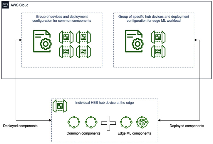
Figure 4.3 – Example of aggregating components across group deployments
As mentioned earlier, your deployment configuration can specify whether to allow components an option to signal they are ready for a restart or update. The value of letting components interact with deployment behavior in this way is to prevent any loss of data or business process interruption from the component suddenly being terminated. The component must include the use of IoT Greengrass interprocess communication (IPC) with the IoT Greengrass SDK and implement the SubscribeToComponentUpdates function.
A component can then respond to component update events and request a deferment by publishing a message back over IPC using the DeferComponentUpdate command. There is a similar operation for components to validate configuration change requests with SubscribeToValidateConfigurationUpdates and the respective SendConfigurationValidityReport features. You can learn more about these features from the References section at the end of this chapter.
With your first remote deployment complete and with a better understanding of how the deployment service of IoT Greengrass works, let's make it easier to remotely troubleshoot your hub device and its components by enabling the publication of local logs to the cloud.
Storing logs in the cloud
An edge solution loads resources from the cloud in order to bootstrap, configure, and generally make the local solution ready for runtime. The health of the device and the solution should also be reported to the cloud to assist with production operations. By default, your HBS hub device checks in with the cloud IoT Greengrass service to report connectivity status and the result of the most recent deployment. To get more telemetry from the edge solution, such as logs and metrics, you need to deploy additional components. In this section, you will deploy a managed component that ships component logs up to Amazon CloudWatch, a service for storing and querying logs.
Storing the logs of our hub devices in the cloud is a best practice and enables us to triage devices individually without needing a live connection to the device or being physically in front of it. After all, some of these devices may be in rather remote locations such as the Alaskan tundra or only come online at scheduled times, such as the narwhal-studying submersible from Chapter 1, Introduction to the Data-Driven Edge with Machine Learning.
Another benefit of storing logs in the cloud is that you can run queries across a fleet of devices to discover insights about fleet performance. For example, a simplistic count of lines per device log over a 24-hour period could find outliers of chatty devices where there is an abnormal amount of activity, which could mean the device is processing an unusual amount of data or thrashing resources. The following histogram of log activity across our fleet would indicate a potential problem for your operations team to triage:
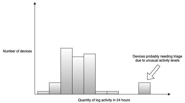
Figure 4.4 – Sample histogram showing device outliers based on log activity
Since storing logs is such a common use case for an edge solution and also in the wider spectrum of cloud application development, IoT Greengrass provides a managed component to make it easy to ingest your components' logs. This managed component, called aws.greengrass.LogManager, is authored and maintained by AWS. Managed components are anticipated as fulfilling common requirements of IoT architects but deemed as opt-in features that you need to bring in with your deployments.
Note
The latest version of the aws.greengrass.LogManager managed component at the time of this writing was 2.2.0. You may need to update the version based on the latest version of IoT Greengrass core software installed when you started this book. For the steps in Chapter 2, Foundations of Edge Workloads, IoT Greengrass core software version 2.4.0 was used, which is compatible with LogManager 2.2.0. You can see the latest dependency information in the AWS-provided components documentation link in the References section found at the end of this chapter.
In the following steps, you will revise the deployment for the hbshubprototypes group to include the aws.greengrass.LogManager managed component. The configuration for the LogManager component will specify which components to upload log files to. Then, you will use the AWS CLI to run a simple query to validate that log files are being stored. Proceed as follows:
- Edit the chapter4/deployment-logmanager.json file to swap the placeholder with your account ID. This deployment adds the LogManager component. Remember that by not specifying other components in the deployment list—such as com.hbs.hub.HelloWithConfig, which you added in a previous section—they will be removed from the device. We will remove HelloWithConfig for this deployment so that we can see the runtime output to the log file when we add it back. All you need to do is update the targetArn property to replace the account ID placeholder and save the file.
- Create a new deployment revision and pass in this new deployment configuration file, as follows: aws greengrassv2 create-deployment --cli-input-json file://deployment-logmanager.json.
- Edit the chapter4/deployment-logmanager.json file to once again add the HelloWithConfig component. We do this to redeploy the component so that the runtime output is written to the log again and will then be uploaded to the cloud. Add the following bolded lines into the components object and save the file:
{
"targetArn": "arn:aws:iot:us-west-2:0123456789012:thinggroup/hbshubprototypes",
"components": {
"aws.greengrass.Cli": {
"componentVersion": "2.4.0"
},
"com.hbs.hub.HelloWithConfig": {
"componentVersion": "1.0.0"
},
"aws.greengrass.LogManager": {
- Create a new deployment revision using the same command as before, like this: aws greengrassv2 create-deployment --cli-input-json file://deployment-logmanager.json.
- Once this deployment is complete, you will start seeing logs in CloudWatch Logs within 5 minutes since the configuration for LogManager specifies 300 seconds as the periodicUploadIntervalSec parameter.
- Use the following command to check on the status of new log groups with the prefix: /aws/greengrass/: aws logs describe-log-groups --log-group-name-prefix "/aws/greengrass/".
- You know logs are being written to CloudWatch when you see a response such as the following:
{
"logGroups": [
{
"logGroupName": "/aws/greengrass/UserComponent/us-west-2/com.hbs.hub.HelloWithConfig",
"creationTime": 1627593843664,
"metricFilterCount": 0,
"arn": "arn:aws:logs:us-west-2:012345678912:log-group:/aws/greengrass/UserComponent/us-west-2/com.hbs.hub.HelloWithConfig:*",
"storedBytes": 2219
}
]
}
- You can query the log group to see devices that are storing logs for this component, as follows: aws logs describe-log-streams --log-group-name /aws/greengrass/UserComponent/us-west-2/com.hbs.hub.HelloWithConfig.
- The response, as illustrated in the following code snippet, will show log streams named in a /DATE/thing/THING_NAME format:
{
"logStreams": [
{
"logStreamName": "/2021/07/29/thing/hbshub001",
- Plug the log group name into the filter-log-events command to see the logged output of the HelloWithConfig component, as follows: aws logs filter-log-events --log-group-name /aws/greengrass/UserComponent/us-west-2/com.hbs.hub.HelloWithConfig --filter-pattern stdout.
The output is as follows:
{
"events": [
{
"logStreamName": "/2021/07/29/thing/hbshub001",
"timestamp": 1627579655321,
"message": "2021-07-29T17:27:35.321Z [INFO] (Copier) com.hbs.hub.HelloWithConfig: stdout. Hello from Zimbabwe!. {scriptName=services.com.hbs.hub.HelloWithConfig.lifecycle.Run, serviceName=com.hbs.hub.HelloWithConfig, currentState=RUNNING}",
"ingestionTime": 1627593843867,
"eventId": "362…"
}
]
}
You can see from this series of instructions how to include the LogManager component that will automatically ship your components' log files to the cloud and how to use the Amazon CloudWatch Logs service to query into your logs. IoT Greengrass makes it easy to triage log files of one component across a fleet of devices by querying the log group or into individual devices by querying the log stream that represents one device's component. For more powerful log analysis tooling, you can explore Amazon CloudWatch Logs Insights for aggregation queries across log groups, or stream logs into an indexed querying tool such as Amazon Elasticsearch.
Merging component configuration
Now is a good opportunity to introduce how to merge in component configuration at deployment time, which you can see we are doing in deployment with logmanager.json. If you recall from earlier recipe creation in the Writing your first component section of Chapter 2, Foundations of Edge Workloads, the recipe can define a ComponentConfiguration object that specifies the default settings that a component will use at runtime. We used this to define a default World! text that gets passed into the HelloWorld component. This kind of component configuration can also be defined at the time of deployment to one or more devices to override these defaults. This is useful when setting the configuration for distinct groups of devices, such as telling all of our prototype devices to use verbose debug-level logging and our production devices to use warning-level logging to save on costs. Here is an illustration of that practice in effect:
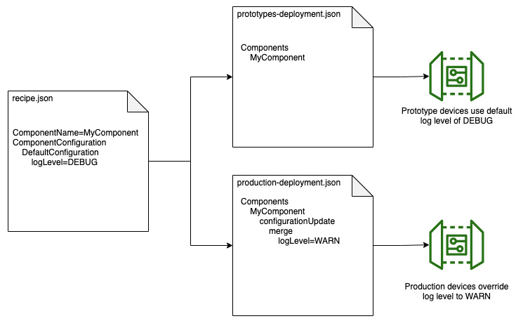
Figure 4.5 – Overriding configuration for fleets of devices
A deployment can define component configuration using either of two properties, reset and merge. The reset property tells the component to restore the configuration to whatever the default is for the given configuration key. The merge property tells the component to apply a new configuration for the given configuration key, without affecting existing values of other configuration keys. Using both the reset and merge property on the same configuration key will always first reset the value and then merge in the new value. This can be useful for restoring a tree of default values and then merging in an update for just one node in the tree.
If you inspect the deployment-logmanager.json file, you can see the deployment-time configuration merge we are using to tell the LogManager component what to do. Here is a pretty-print version of the merge object:
{
"logsUploaderConfiguration": {
"systemLogsConfiguration": {
"uploadToCloudWatch": "true",
"minimumLogLevel": "INFO",
"diskSpaceLimit": "10",
"diskSpaceLimitUnit": "MB",
"deleteLogFileAfterCloudUpload": "false"
},
"componentLogsConfigurationMap": {
"com.hbs.hub.HelloWithConfig": {
"minimumLogLevel": "INFO",
"diskSpaceLimit": "10",
"diskSpaceLimitUnit": "KB",
"deleteLogFileAfterCloudUpload": "false"
}
}
},
"periodicUploadIntervalSec": "300"
}
Without any merged configuration set in the deployment, the version 2.2.0 LogManager component used here doesn't actually do anything. You must give it some configuration at deployment time to get any logs sent to the cloud.
In the preceding sample, there is a logsUploaderConfiguration configuration key that has two child nodes and an interval property. The systemLogsConfiguration node tells the LogManager component to upload to Amazon CloudWatch IoT Greengrass system logs such as greengrass.log. The componentLogsConfigurationMap node tells the LogManager component how to selectively upload logs for your other components. You can see here we are defining a com.hbs.hub.HelloWithConfig component for inclusion to send logs to the cloud. You would add one object to this list for each component to explicitly capture logs. Two best practices to consider are outlined here:
- Generate your deployment configuration programmatically and build out the LogManager configuration based on the other components included in that deployment. A script in a build process that inspects the components included in your deployment can update the LogManager componentLogsConfigurationMap node before it gets passed to the CreateDeployment API.
- Create a thing group, such as CommonMonitoringTools, put all of your Greengrass devices in it, and set a group-level deployment configuration to capture the system logs in the systemLogsConfiguration node. All of your devices would then include this component and configuration, resulting in a default behavior to upload system logs. A separate thing group deployment that represents your application's components would then merge the LogManager configuration for the componentLogsConfigurationMap node in order to specify the logs for that application's components. This works because two deployments from two different thing groups can stack on a single device, effectively merging the configuration of a single component. Figure 4.3 and Figure 4.5 together illustrate this concept.
One last note on configuration management is addressing the delta between the preceding pretty-printed JavaScript Object Notation (JSON) and the escaped JSON string you see in deployment-logmanager.json. At the time of this writing, the IoT Greengrass deployment API only accepts the configuration as a string object, so the configuration must be defined as JSON and then escaped as a single string before sending it to the deployment API. This is more inconvenient when hand-writing deployment files but is a simple added step when building deployments programmatically. An alternative, in this case, could be to define your deployment files using the YAML Ain't Markup Language (YAML) format instead of JSON because the YAML specification has syntactical support for constructing multiline inputs.
You now have a functioning, managed component for storing your hub's log files in the cloud to facilitate remote diagnostics for your edge solution. You know how to add more components to the LogManager component by merging in new changes to the configuration. Through that process, you learned more about the component configuration system of IoT Greengrass that will serve you as you create new components and build deployments with multiple components working together. In the next section, you will learn how leaf devices connected to your hub can exchange messages and synchronize the state with the cloud.
Synchronizing the state between the edge and the cloud
The HBS hub device, if made into a real product, would connect with local devices over a network protocol and proxy telemetry and commands with a cloud service. In the previous chapter, we used components running on our hub device to interface with local hardware interfaces on the Raspberry Pi Sense HAT.
This makes sense when the hub device communicates with hardware over serial interfaces, but when communicating over a network, those appliance monitoring kits won't really be software components running on the hub device using the Greengrass IPC interface to exchange messages. Instead, they may use a network protocol such as Message Queue Telemetry Transport (MQTT) to exchange messages with the hub device over Wi-Fi or Bluetooth.
In this section, you will deploy new managed components for connecting to leaf devices over MQTT and synchronize the state of a leaf device's telemetry to the cloud.
Introduction to device shadows
By synchronizing state, we mean the end result of keeping two systems up to date with the latest value. When working with the edge and cloud, we must acknowledge and work with the reality that edge solutions may not currently be connected to the cloud service. Our leaf devices and the hub device may work with acquired telemetry that has yet to be reported to the cloud. Once the hub device restores the connection with the cloud, there must be a mechanism for reconciling the current state of the edge and the current state of the cloud.
For example, if our hub device is disconnected from the cloud because of a network drop, new telemetry will be acquired by the leaf devices and new remote commands could be queued up from the cloud service from the customer's mobile application. When the connection is restored, something needs to update the device state so that everything gets back in sync. For this purpose, AWS IoT Core offers a service called Device Shadow that acts as a synchronization mechanism for devices and the cloud. IoT Greengrass makes this Device Shadow service available at the edge via a managed component.
A device shadow is a JSON document that summarizes the current state of reported data and the desired state. Typically, this means that the device is responsible for updating the reported data, and other actors in the system instruct the device using the desired state. Let's say our hub device is supposed to keep the cloud informed of the latest temperature measurement from one of the appliance monitoring kits. Let's also say that the customer's mobile application can send a command to restart the monitoring kit as a form of troubleshooting. The following diagram illustrates how these messages are stored in the device shadow and reconciled after resuming from a network drop event:
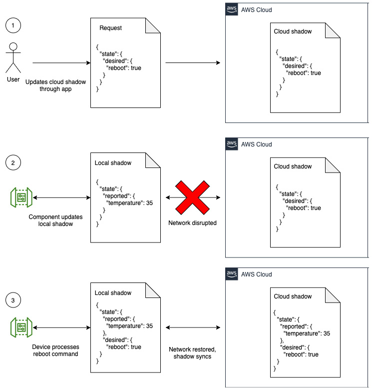
Figure 4.6 – Flow of shadow messages synchronizing after a network disruption
Device shadows are also useful for our edge ML workloads since a component running an inference task can subscribe to changes reported by the shadow service, or even register its own shadow for exchanging state and commands with the cloud and other components running on the Greengrass device.
In the Connecting your first device: sensing at the edge and Connecting your second device: actuating at the edge sections of Chapter 3, Building the Edge, you implemented IPC in order to let components exchange information in real time. Shadows can level up your edge solutions by defining synchronized state documents that also get communicated over IPC or even synchronized with the cloud. This opens up some interesting use cases that further let you as the architect focus on solving business problems without also engineering mechanisms for data exchange. Here are a few examples of how ML workloads running as edge components can benefit from using shadows:
- Reporting and caching application state: Your ML inference component can create a local shadow that stores the latest inference results whenever the ML model is used to process new data. If the model is trained to report when there is an anomaly detected on new data, the local shadow could store the latest anomaly score and confidence rating. That way, other components on the device can subscribe to changes in the shadow and alter their behavior based on the output of the ML component. This may seem similar to publishing updates over IPC, but the key difference here is that components can get values from the shadow whether or not they were running at the same time as when the ML component last published the anomaly score. In that sense, the shadow is used as a caching mechanism and helps us decouple our edge solution.
- Sending commands to components: Shadows can be used to instruct components of new commands or desired behavior, even if the component is not currently running. For example, if a component crashes or is in some other recovery state at the time a command would have otherwise been sent to it, putting that command in a shadow ensures it will be delivered to the component when it next enters its running state. Combined with synchronizing shadows to the cloud AWS IoT Core service, this enables other applications and devices to interact with components at the edge in a resilient way.
Now that we have introduced state synchronization with shadows, let's move on to the hands-on steps for deploying this functionality to your solution.
Steps to deploy components for state synchronization
IoT Greengrass provides the functionality for connecting leaf devices, storing shadows, and synchronizing messages to the cloud with a few separate managed components. Those components are an MQTT broker (aws.greengrass.clientdevices.mqtt.Moquette), Shadow Manager (aws.greengrass.ShadowManager), and an MQTT bridge (aws.greengrass.clientdevices.mqtt.Bridge), respectively.
The following diagram illustrates the architecture of this solution and how these components work together to deliver state synchronization for devices:

Figure 4.7 – Examples of message flows using managed components
By following the next steps of this section, you will create a new deployment that enables all three of these managed components to launch a new standalone application on your C2 system that connects to your hub device over MQTT and observe how the state is synchronized between the edge and the cloud using these features. Proceed as follows:
- Update your Greengrass role in AWS IAM to allow the use of the device shadow APIs of AWS IoT Core. These steps are specific to AWS IAM and represent a common flow of preparing your Greengrass device to use new APIs. Then, do the following:
- From the chapter4 directory, create a new IAM policy, as follows: aws iam create-policy --policy-name greengrass-use-shadows --policy-document file://greengrass_use_shadows.json --description "Allows Greengrass cores to interact with AWS IoT Core device shadows".
- Copy the policy ARN from the response of the create-policy command and use it in the attach-role-policy command next. It will look like this, but with your account number instead: arn:aws:iam::01234567890:policy/Greengrass-use-shadows.
- Attach the new policy to your Greengrass IAM role, replacing the policy-arn argument with your own from the previous step, as follows: aws iam attach-role-policy --role-name GreengrassV2TokenExchangeRole --policy-arn arn:aws:iam::01234567890:policy/Greengrass-use-shadows.
- Edit the deployment-syncstate.json file to update the targetArn property for your account ID. Save the file.
- Create a new deployment using the deployment-syncstate.json file. Confirm the deployment is complete and successful before moving on to the next step. You can use the list-effective-deployments AWS CLI command to verify or check the status in the AWS IoT Greengrass management console at https://console.aws.amazon.com/iot.
- Launch the local device client to connect to your hub device over MQTT. From the chapter4/apps directory of the GitHub repository, run the following command: ./client.sh.
The script at apps/client.sh uses your AWS credentials to register a new device in AWS IoT Core, downloads a generated x.509 private key and certificate, and adds the device to the list of associated devices for your Greengrass core. It then installs the AWS IoT Device SDK for Python and launches a Python application that discovers your hub device on the local network and connects to it for exchanging messages over MQTT. The purpose of running this application off of the hub device is to demonstrate how Greengrass supports exchanging messages for local devices.
Note
If your C2 laptop is not on the same network as your hub device, you can run the client application on your hub device. However, you will need to update the permissions for the idtgg AWS user that was configured on the hub device since it does not have the necessary permissions yet. Return to the AWS management console for IAM, find the user group named Provision-IDT-Greengrass, add a new permission by attaching a policy, and choose the policy named AWSIoTFullAccess. Then, you can run the client.sh application on your hub device using the existing credentials there from Chapter 2, Foundations of Edge Workloads.
The client.sh application will publish new messages on a topic dedicated to device shadow communications. The topic address is $aws/things/localdevice/shadow/update. The client reports a randomly generated temperature value as if it were another sensor on the local network. You can verify that these messages are making it up to the cloud by using the AWS IoT Core management console at https://console.aws.amazon.com/iot. Navigate to Test > MQTT test client and subscribe to the $aws/things/localdevice/shadow/update/accepted topic to see the result of the publishing. Here is an example of what it looks like:
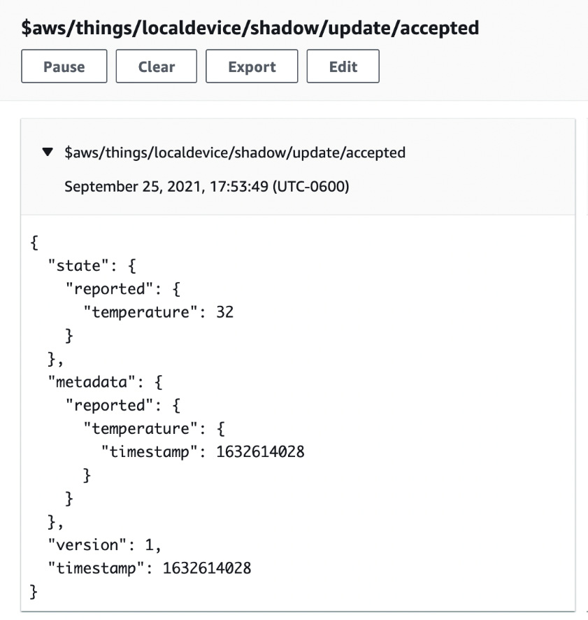
Figure 4.8 – Screenshot from AWS IoT Core console of the accepted shadow update
You can interact with the local device application through this test client, too. You can send a new desired state to the local device and it will merge the command into the next reported message. Use the MQTT test client to publish a message on the $aws/things/localdevice/shadow/update topic with this body: {"state":{"desired":{"valve":"open"}}}. You should see on your subscription and in the standard output of the client.sh application activity that it shows the open valve now in the reported state instead of the desired state. This means the local device received a command through Greengrass, processed the command, and updated its reported state accordingly.
You can continue experimenting with this by publishing further messages to the desired state through the MQTT test client. A real device would take some action in response to the desired state, but this application just copies the command from the desired state to the reported state to simulate handling the event.
To demonstrate the functionality of the MQTT bridge managed component, the client.py application is also publishing a heartbeat message on another topic at the dt/localdevice/heartbeat address. The reason for this is that the Shadow Manager component actually handles all the synchronization of state for us when using the shadow topics. For any other topics and data published, such as this heartbeat behavior, we must use the MQTT bridge component to ferry messages from the edge to the cloud (or vice versa). Use the MQTT test client to subscribe on dt/localdevice/heartbeat to see these messages arrive in the cloud.
Something fun to try is to take your hub device offline temporarily and repeat the previous step but set the desired state of the valve to closed. This will demonstrate how the shadow service messages are buffered for delivery the next time the Greengrass device comes back online. On your hub device, bring down the network connection (either by unplugging the Ethernet cable or disabling Wi-Fi). You should see no more messages arriving on either the shadow or heartbeat topics in the MQTT test client. Publish a new message in the MQTT test client, such as {"state":{"desired":{"valve":"open"}}}, and then bring the network connection back up. You will see the local device get the new command once the hub device reestablishes connectivity as well as a resumption of the heartbeat messages.
Extending the managed components
The deployed example uses components managed by AWS to establish connectivity for local devices over an MQTT broker, sending and receiving messages between the edge and the cloud, and synchronizing state with the device's shadow service. You can configure these components for your own use cases by merging further configuration updates. Let's examine the configuration used in this deployment, then review a few more options and best practices.
Note
For any configuration JSON reviewed in this section, the book is using a pretty-print format that doesn't match what you see in the actual deployment files where JSON is stringified and escaped per the API requirements. This is done for convenience and legibility in the book format.
Shadow Manager
In the aws.greengrass.ShadowManager component configuration of the deployment-syncstate.json file, we must explicitly define which device shadows will be kept in sync between the edge and cloud. The configuration we used defined the shadow to synchronize for a device named localdevice that matches the client ID of the apps/client.sh application. Here is the configuration used to achieve that:
{
"synchronize":{
"shadowDocuments":[
{
"thingName":"localdevice",
"classic":true,
"namedShadows":[]
]
}
}
A classic shadow is a root-level shadow for any device in AWS IoT Core. Named shadows are children that belong to the device, and a device can have any number of additional children shadows to help with separation of concerns (SoC). In this case, just using a classic shadow is sufficient.
For each device you want your Greengrass solution to keep in sync, you would need the configuration to specify that device in the list of shadowDocuments where thingName is the name of your device that it uses to connect over MQTT (AWS IoT Core defines many resources and APIs representing devices as things per the IoT moniker).
Your Greengrass core device is itself a thing registered in AWS IoT Core and can use both classic and named shadows. These shadows can be used for representing the state of the hub device itself or for components on the hub device to behave in coordination with some desired command; for example, sending the desired state to the hub device's shadow to enter a low bandwidth state could get picked up by any components running on the device to act accordingly. Enabling shadow synchronization for your Greengrass core device has a separate configuration outside of the shadowDocuments property. Here is an example of how that could look:
{
"synchronize":{
"coreThing":{
"classic":true,
"namedShadows":[
"CoreBandwidthSettings",
"CorePowerConsumptionSettings"
]
},
"shadowDocuments":[ ... ]
}
This section covered what you need to know about shadows in AWS IoT Core and how to configure the Shadow Manager component. Next, let's review the MQTT bridge component.
MQTT bridge
The aws.greengrass.clientdevices.mqtt.Bridge component is responsible for relaying messages between the three kinds of messaging channels supported by Greengrass. The three kinds of messaging channels are listed here:
- Local IPC topics that components use for messaging
- Local MQTT topics enabled by the Moquette MQTT broker component
- Cloud MQTT topics from using AWS IoT Core
Configuring the MQTT bridge enables you to create flows of messages from a topic on one channel across the boundary to a topic on another channel—for example, copying messages published on the dt/device1/sensors IPC topic to the dt/sensors/all AWS IoT Core topic for cloud ingestion.
Similar to the Shadow Manager component, each mapping of source and destination topics must be explicitly defined in the component's configuration. To enable the heartbeat messages arriving from the client.sh application to the cloud, we used the following configuration in the MQTT bridge:
{
"mqttTopicMapping": {
"ForwardHeartbeatToCloud": {
"topic": "dt/localdevice/heartbeat",
"source": "LocalMqtt",
"target": "IotCore"
}
}
Rather than create one mapping for every single device that used the heartbeat pattern, you could make use of MQTT wildcards and update the topic to dt/+/heartbeat. The best practice is to explicitly define one mapping for each expected device and avoid wildcards unless you have a use case where devices may be migrating between multiple gateway devices and cannot predict specifically which devices may be publishing. Wildcards are great for simplifying manually typed configuration and for legibility but introduce a risk of unanticipated behavior. Wildcards are also not supported for the Pubsub type of topic used for IPC.
Here is another example of using an MQTT bridge to allow delivery of commands from other AWS IoT Core devices or applications directly to a component running on a Greengrass core. The idea of this example is how we might update the settings of all ML-powered components to adjust the rate at which models are used in inference activities. Components subscribed over IPC to the topic can receive updates without requiring a full Greengrass deployment:
{
"mqttTopicMapping": {
"RemoteUpdateMLComponents": {
"topic": "cmd/ml-components/inferenceRate",
"source": "IotCore",
"target": "Pubsub"
}
}
You have now finished deploying managed components for the purposes of moving messages back and forth between the edge and the cloud. This functionality creates a path for local devices to communicate with each other through the hub device, for components to interact with cloud services, and any other combination of local devices, components, and the cloud exchanging messages. You also learned how AWS IoT Core and the Device Shadow service work to synchronize the state for local devices and components built on the underlying messaging systems. These tools enable you to build edge ML solutions with any kind of messaging requirements without writing any code or managing infrastructure for your messaging needs.
In the next section, you will deploy your first ML model using a combination of prebuilt models, inference code, and a custom component for acting on inference results.
Deploying your first ML model
Now that you are familiar with remote deployments and loading resources from the cloud, it is time to deploy your first ML-powered capability to the edge! After all, a component making use of ML models is much like other components we have deployed. It is a combination of dependencies, runtime code, and static resources that are hosted in the cloud.
Reviewing the ML use case
In this case, the dependencies are packages and libraries for using OpenCV (an open source library for computer vision (CV) use cases) and the Deep Learning Runtime (DLR), the runtime code is a preconfigured sample of inference code that uses DLR, and the static resources are a preconfigured model store for image classification and some sample images. The components deployed in this example are all provided and managed by AWS.
The solution that you will deploy simulates the use case for our HBS device hub that performs a simple image classification as part of a home security story for our customers.
Let's say an add-on device that HBS customers can buy for their hub is a security camera that notifies the customer when a person has approached the front door. A camera device takes a picture on an interval or paired with a motion sensor and stores that image as a file on the hub device. The hub device then performs an inference against that image using a local ML model to identify if any person is detected. If so, an audio notification can be played on the hub device or a text notification sent to the customer. Here is an illustration of the solution and its parts:

Figure 4.9 – Sample architecture for audio notification of subject recognized by the camera
Today, this kind of security capability has many products in the market. However, what is not yet common is performing the ML inference at the edge. This presents a key opportunity for differentiation because the total cost of ownership (TCO) goes down by saving bandwidth on image transfer to the cloud and saving the compute costs of running the ML inference in the cloud. The security solution will remain operational even if the customer's internet service is disrupted and has no dependency on the availability of a cloud service. There are also tangible benefits for processing and notification latency, as well as a privacy story that appeals to customers since any image data is kept locally.
This use case demonstrates all four of the key benefits for ML deployed to the edge that we covered in Chapter 1, Introduction to the Data-Driven Edge with Machine Learning: latency, availability, cost, and governance.
Steps to deploy the ML workload
The steps to take for this section are pretty simple, thanks to the managed components provided by AWS. There are three components to deploy from the AWS catalog and one more custom component to process the inference results. Since the target prototype hardware of Raspberry Pi and Sense HAT does not include any camera interface, we will lean on the sample image provided in the managed component to emulate the sensor. The one custom component serves as our actuator, and it will display the inference results on the light-emitting diode (LED).
Note
If you are not using the target Raspberry Pi and Sense HAT hardware, you must alter the steps to use the com.hbs.hub.ScrollMessageSimulated component instead. Alternatively, you can view inference results using the AWS IoT Core management console (covered in Step 5), any other MQTT client connecting to AWS IoT Core (subscribe to the topic marked in Step 5), or review the inference component logs (locally on the device or add these logs to the LogManager configuration).
The following steps deploy the ML solution to the hub device:
- Update the Raspberry Pi to install OpenCV dependencies. We are taking a shortcut here by manually installing dependencies instead of adding complexity to the example (more on this after the steps). Other target platforms should only need glibc installed, and the managed components will install dependencies as needed. Open an ssh connection to your Pi or open the Terminal program directly on the device. Run the following command: sudo apt-get install libopenjp2-7 libilmbase23 libopenexr-dev libavcodec-dev libavformat-dev libswscale-dev libv4l-dev libgtk-3-0 libwebp-dev.
- Create a new custom component in your AWS account from the book repository's source for the com.hbs.hub.ScrollMessage component. These are the same 1-4 steps from the Registering a component in IoT Greengrass section. Upload the archive.zip file for this component to S3, edit the recipe file to point at your artifact in S3, then register the new custom component.
- Edit the deployment-ml.json file to update the targetArn property, as in past sections. Save the file.
- Create a new deployment using the deployment-ml.json file, as follows: aws greengrassv2 create-deployment --cli-input-json file://deployment-ml.json.
- When the deployment concludes (it can possibly take a few hours to install the bundled DLR dependencies on the Pi), you should start seeing new inference results appear on your Sense HAT LED matrix. For readers not using the Raspberry Pi with Sense HAT, you can view results using the AWS IoT Core management console. Log in to https://console.aws.amazon.com/iot, navigate to Test > MQTT test client, and subscribe to the ml/dlr/image-classification ML inference topic.
If you are using the AWS IoT Core console or an MQTT client to check the inference results, they should look something like this:
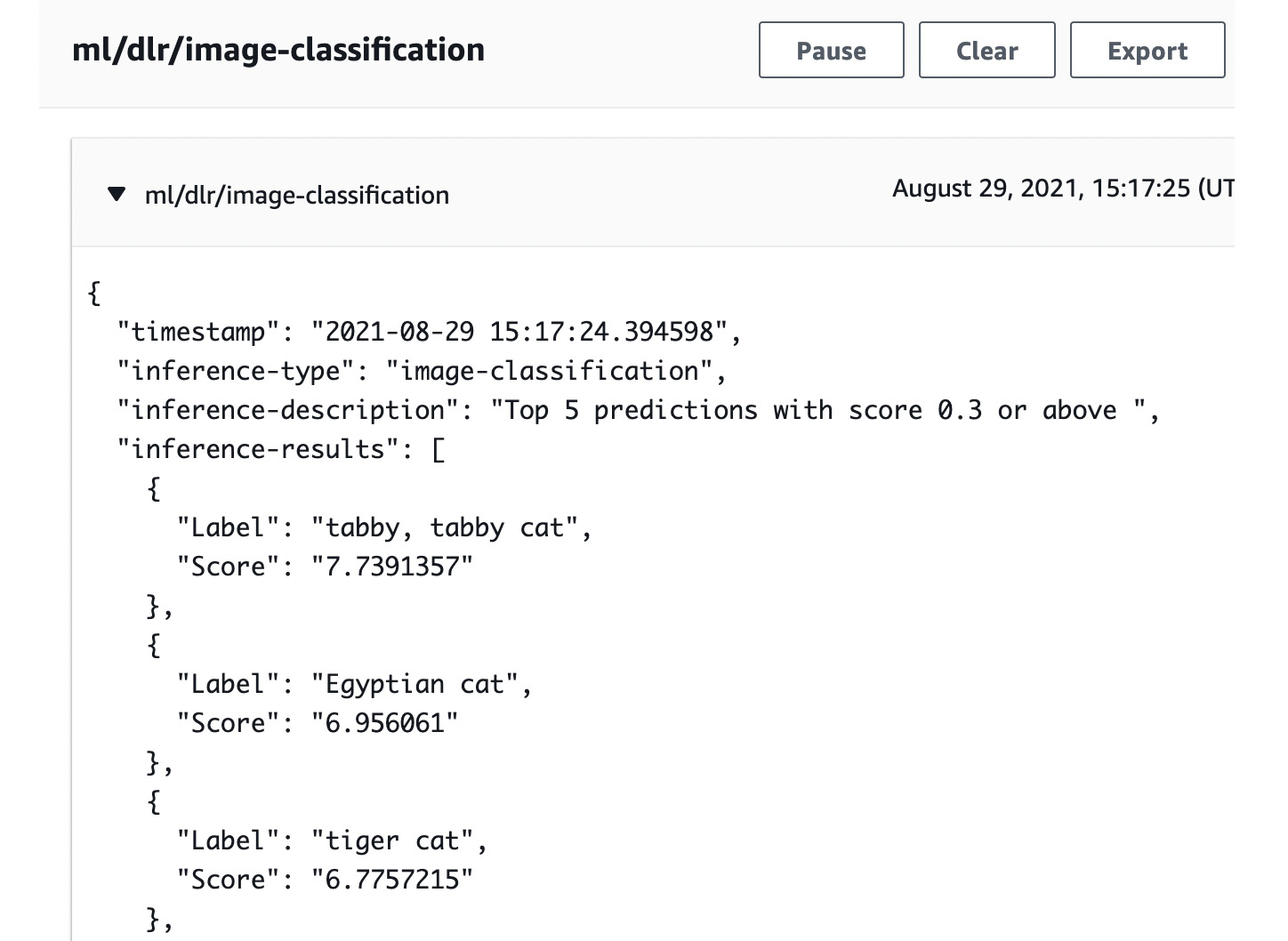
Figure 4.10 – Screenshot of the inference results in AWS IoT Core
You have now deployed your first ML workload to the edge! This workload will continue to run at a 10-second interval and will process the file found at /greengrass/v2/packages/artifacts-unarchived/component-name/image_classification/sample_images/cat.jpeg on the hub device. There are a number of ways to extend this example for your own testing and use cases, such as the following:
- Pass in alternate images to the inference component: You can merge in a new configuration for the aws.greengrass.DLRImageClassification component to specify where to source the processed image—for example, you can specify a new directory with the ImageDirectory parameter and a filename with the ImageName parameter. Then, you could create a custom component that includes your own images as artifacts and rotates them through that filename at that path to see what the classification engine identifies.
- Hook up a camera as input: You can merge in a new configuration for the aws.greengrass.DLRImageClassification component to specify a camera as the source for images to classify. For prototyping on the Raspberry Pi device, you can connect a Universal Serial Bus (USB) webcam or the Raspberry Pi Camera Module v2. More details on how to set up the component to use a camera can be found in the References section at the end of this chapter.
- Escalate an event for a type of classified result: The current workload reports all inference results on a specified topic. You could modify the custom component that subscribes to these results and only update the actuator when a human is classified in the inference results. Alternatively, you could publish a message on another topic reserved for alerts and configure AWS IoT Core and Amazon Simple Notification Service (Amazon SNS) to send you an alert when a human is detected. For these events, you may also want the detected image to be stored for future reference.
- Deploy object detection workload: This example demonstrated a use case for classifying the primary object in the source image. An alternate use case is to list all objects detected in the source image. AWS also provides managed components for object detection workloads and for CV use cases running on either DLR or the TensorFlow framework.
- Notify of new images available: The managed component is designed with an interval pattern to process the source image against the ML model. You could design a variation that subscribes to a local IPC topic and waits for notification from another component that an inference is needed and could specify the file path in the message.
As mentioned in the step for installing the dependencies on the Raspberry Pi, these steps take a shortcut that doesn't reflect the best practices of our solution design. Rather than manually installing dependencies on the device, a better way is to use IoT Greengrass to install those missing dependencies. This section could have walked you through forking the AWS managed components in order to add more dependencies in the install lifecycle step, but for the purposes of this exercise was deemed not a valuable detour.
Furthermore, the default behavior of the aws.greengrass.DLRImageClassification managed component publishes the inference results to a cloud topic on AWS IoT Core instead of a local topic on IPC. For workloads that report all activity to the cloud, this is the desired behavior. However, given the best practices outlined in this book to perform data analysis locally and decouple our components, it would be preferred to publish on a local IPC topic and let another component decide which messages to escalate to the cloud.
This could not be achieved with a simple configuration update as defined in version 2.1.3 of the component. Again, a detour to fork the component just to swap out the cloud publish for a local publish was not deemed valuable for the purposes of this exercise, so the cloud publish behavior is left as-is.
With your first ML-powered workload deployed, you now have an understanding of how ML components are deployed to the edge as a combination of dependencies, code, and static resources.
In this section, you deployed three components as a decoupled set of dependencies, runtimes, and models, plus one more custom component that acts upon the inference results of your ML model. Together, you have all the basics for extending these components to deliver your own image classification and object detection workloads. Next, let's summarize everything you have learned in this chapter.
Summary
This chapter taught you the key differences in remote deploying of components to your Greengrass devices, how to accelerate your solution development using managed components provided by AWS, and getting your first ML workload on your prototype hub device. At this point, you have all the basics you need to start writing your own components and designing edge solutions. You can even extend the managed ML components to get started with some basic CV projects. If you have trained ML models and inference code being used in your business today as containerized code, you could get started with deploying them to the edge now as custom components.
In the next chapter, Chapter 5, Ingesting and Streaming Data from the Edge, you will learn more about how data moves throughout the edge in prescriptive structures, models, and transformations. Proper handling of data at the edge is important for adding efficiency, resilience, and security to your edge ML solutions.
Knowledge check
Before moving on to the next chapter, test your knowledge by answering these questions. The answers can be found at the end of the book:
- What are some examples that differentiate static and dynamic resources of an edge component?
- Where are your components' artifacts stored so that they can be referenced by your recipe files?
- Can you modify an artifact stored in the cloud after it has been included in a registered custom component?
- Why can't you write to artifact files that have been loaded onto the edge device through deployment?
- True or false: Edge devices can belong to multiple thing groups in the cloud AWS IoT Core service and each thing group can have one active Greengrass deployment associated with it.
- Can you think of a use case for one edge device to receive deployments from multiple thing groups?
- True or false: A single deployment can reset a component's configuration and apply a merge of a new configuration.
- Which of the following managed components is responsible for deploying a local MQTT broker and connecting leaf devices?
MQTT bridge/Moquette/device shadows
- Which of the following managed components is responsible for synchronizing the state between the edge and the cloud?
MQTT bridge/Moquette/device shadows
- Which of the following managed components is responsible for relaying messages between communications channels such as MQTT, IPC, and the cloud?
MQTT bridge/Moquette/device shadows
- How might you design the flow of data from a local IoT sensor to an application running ML inference and play an alarm sound over an attached loudspeaker? Think about the different communications channels available and our best practice of decoupled services. Try sketching it out on paper as if you were proposing the design to a colleague.
References
Take a look at the following resources for additional information on the concepts discussed in this chapter:
- Perform sample image classification inference on images from a camera using TensorFlow Lite: https://docs.aws.amazon.com/greengrass/v2/developerguide/ml-tutorial-image-classification-camera.html
- AWS-provided components: https://docs.aws.amazon.com/greengrass/v2/developerguide/public-components.html
- OpenCV website: https://opencv.org/
- AWS IoT Device Shadow service: https://docs.aws.amazon.com/iot/latest/developerguide/iot-device-shadows.html
- DLR: Compact Runtime for Machine Learning Models: https://neo-ai-dlr.readthedocs.io
- TensorFlow website: https://www.tensorflow.org/