
Chapter 15: Creating a Control Rig with Basic IK Controls for the Robot in UE5
In the previous chapter, we made a Control Rig for our Alien Plant. The Alien Plant Control Rig was a simple forward kinematics (FK) setup. Like we said in Chapter 14, Making a Custom Rig for Our Alien Plant with Control Rig, this is just like a basic parent/child hierarchy setup. In this chapter, we will set up the Control Rig for our Robot Drone. We will learn how to set up inverse kinematics (IK) for the arms of our Robot Drone as well as the rest of the Control Rig.
In this chapter, we will cover the following:
- What is IK?
- Creating the controllers for the robot character
- Ordering the control objects in the correct hierarchy and linking them to joints
- Creating an IK controller and testing the whole rig
Technical requirements
The following are the technical skills and software you need to complete this chapter:
- A computer that can run basic 3D animation software.
- You need to have Blender installed for free from https://www.blender.org/ (at the time of writing). The Blender version in this chapter is 3.1.2, but some older and newer versions will also work.
- You need to have installed Unreal Engine (UE) 5. You can download it from https://www.unrealengine.com/en-US/download.
- You need to have a basic understanding of how to navigate the UE 3D user interface. If you skipped ahead, this was covered in Chapter 6, Exploring Unreal Engine 5.
The files related to this chapter are placed at https://github.com/PacktPublishing/Unreal-Engine-5-Character-Creation-Animation-and-Cinematics/tree/main/Chapter15
What is IK?
A character Animation Rig is normally a combination of FK and IK setups. The spine, neck, and head, plus things such as tails, are normally set up as an FK. However, things such as arms and legs are normally set up as an IK within an Animation Rig. On more advanced Animation Rigs, it is possible to set arms and legs up in such a way that they can switch between the IK and FK, but that is beyond the scope of this book. Most of the time, you want a good IK setup for your arms and legs.
Understanding IK
Imagine we had an arm and a hand. We want to move the hand from A to B. With an FK setup, we will first need to rotate the upper arm joint and then the lower arm joint for the hand to reach B, as shown in Figure 15.1:

Figure 15.1 – FK A to B
In reality, we'll have to keep switching between rotating the upper and lower arm joints until we reach B exactly. This is a very time-consuming process. Very early on in the history of computer animation, they invented a much more practical way to do this.
With an IK setup, we will simply have a controller (in IK setups, this is sometimes called an end effector) on the hand that we move from A to B. The 3D software will then automatically work out what the angles of the upper and lower arm joints should be, not only at the end keyframe of the animation but also on every frame in between, as shown in Figure 15.2:
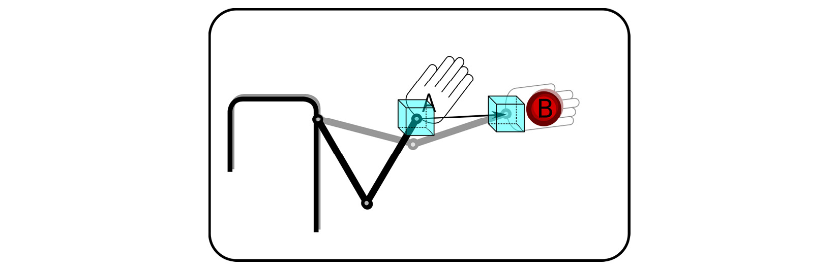
Figure 15.2 – IK A to B
Now, we just have one controller that needs to be animated for a hand to reach its destination. What is maybe even more useful is the fact that it also works in the inverse.
Imagine, for example, that we have a leg, and the foot of our character is planted on the ground while the body moves. We want our foot to stay in exactly the same spot on the ground while the body shifts weight. With an IK setup, the foot will stay with the IK controller (end effector) and lock it in place while the parent/body moves, as shown in Figure 15.3:
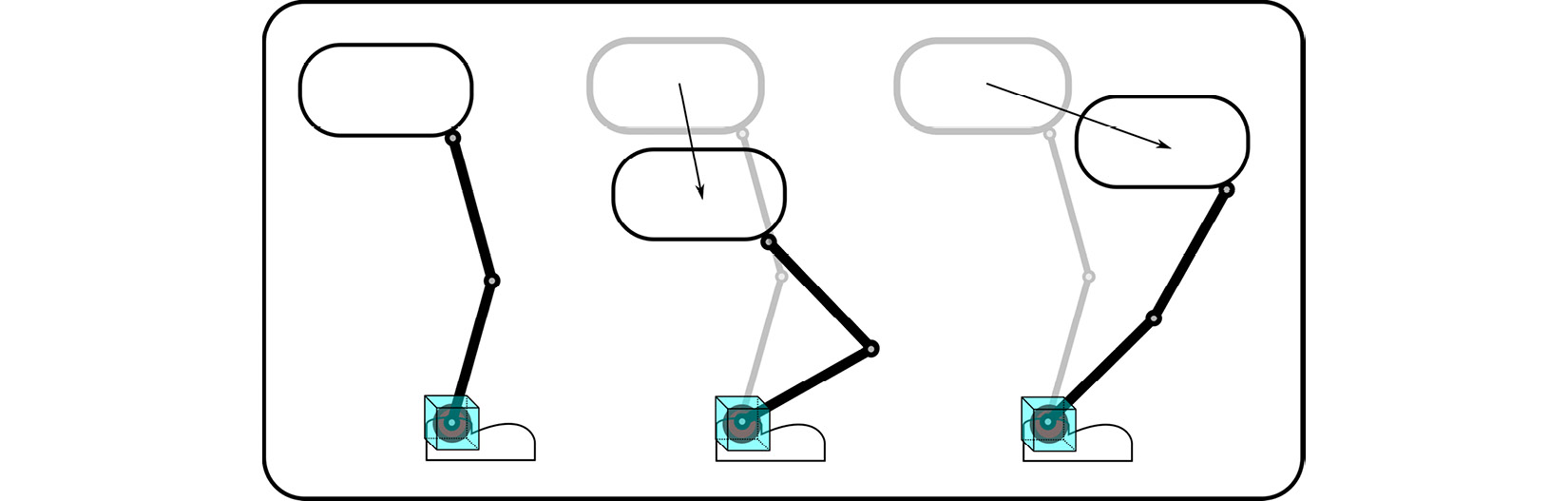
Figure 15.3 – Foot controller
There's one more feature that can be added to most standard IK setups. We can add a controller that controls in what direction the knee or elbow should face when the limb is moving. It is commonly referred to as the pole vector. The knee or elbow will try to point in the direction of this controller. The pole vector controller is B in Figure 15.4:
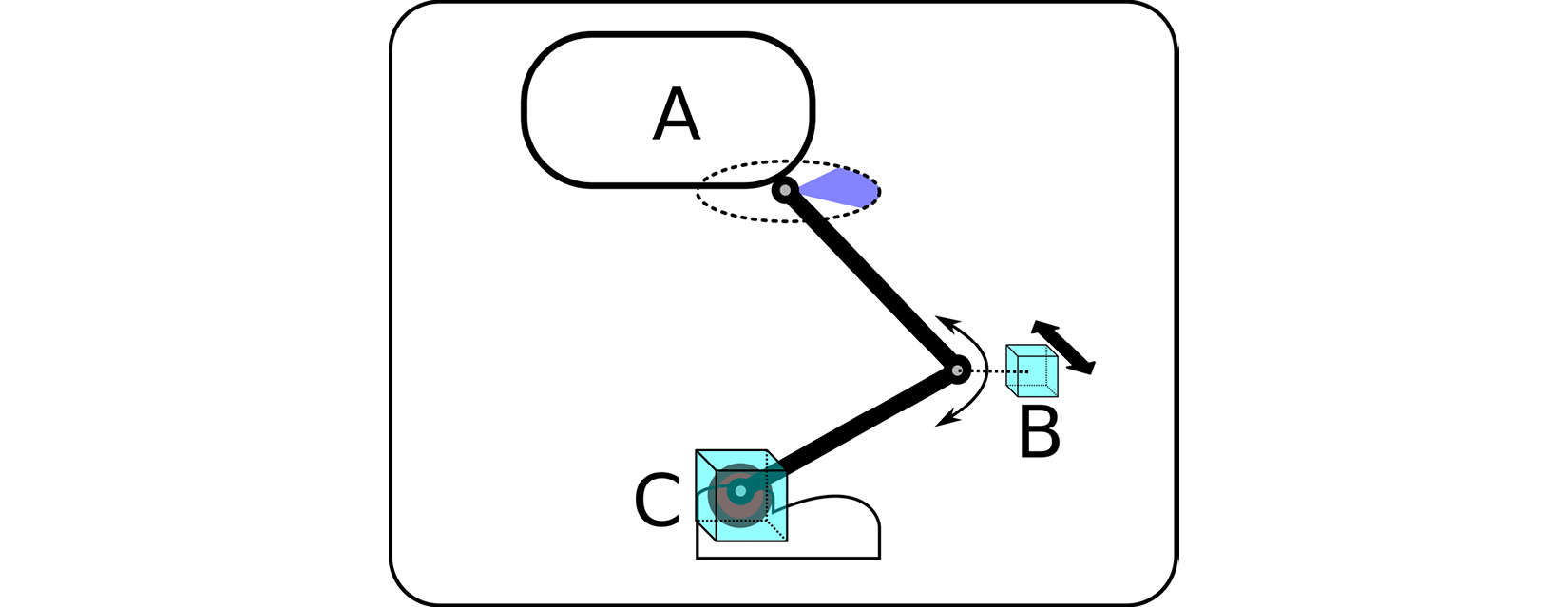
Figure 15.4 – Pole vector
The standard IK setup has three main elements, as shown in the preceding figure:
- A: The parent/base
- B: The pole vector
- C: The end effector
IK setup can be more than two joints, like in the case of the back leg of an animal like a horse, cat, or dog. These setups can be slightly more complex but in principle, they function in roughly the same way.
Now that we have learned what IK is, we can move on to learning how to set it up in a UE Control Rig.
Creating the controllers for the robot character
Next, we will create the Control Rig controllers as we did for the Alien Plant in Chapter 14, Making a Custom Rig for Our Alien Plant with Control Rig.
Exporting the robot and its skeleton from Blender
Before we can start, we need to export the skinned robot and its skeleton from Blender. The Blender file can also be downloaded from https://github.com/PacktPublishing/Unreal-Engine-5-Character-Creation-Animation-and-Cinematics/blob/main/Chapter15/EndOffChapter13_Results_Drone_Skinned.blend. In Blender, we need to select all the parts of the robot as well as the armature and export it as an FBX file. The export settings are the same as what we used for the Alien Plant in the Exporting the Alien Plant from Blender section in Chapter 14, Making a Custom Rig for Our Alien Plant with Control Rig. Figure 15.5 provides an overview of the important robot export settings:
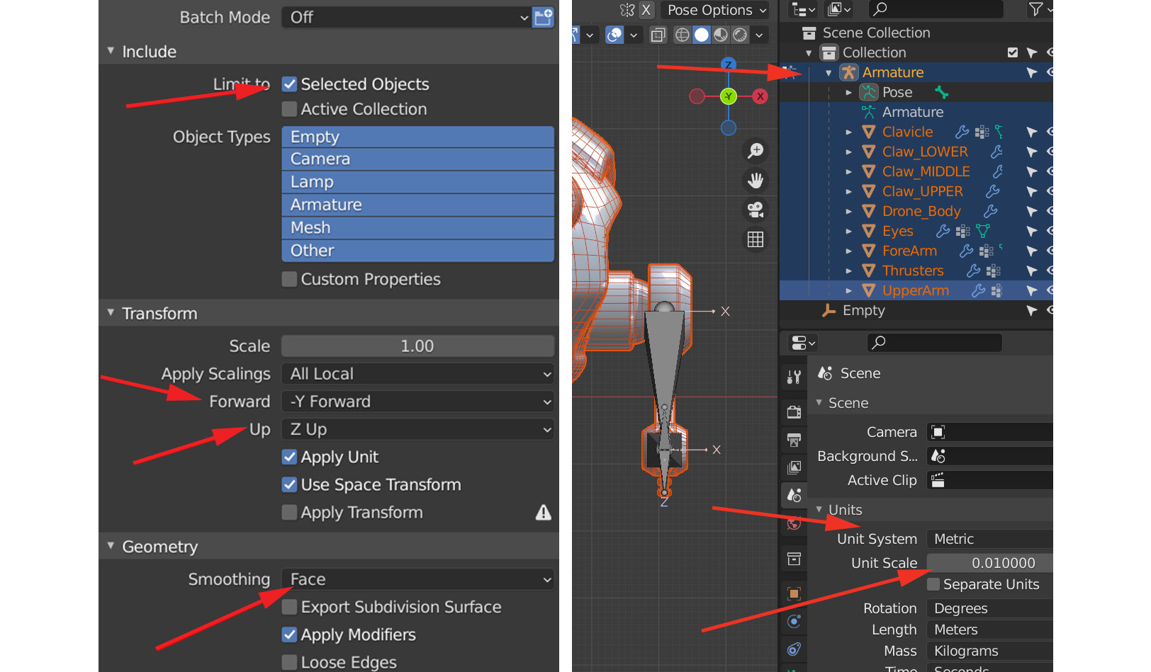
Figure 15.5 – Robot export settings
We have provided an already exported example of the Robot Drone if you want to use that instead. This exported FBX file can be downloaded here: https://github.com/PacktPublishing/Unreal-Engine-5-Character-Creation-Animation-and-Cinematics/blob/main/Chapter15/EndOffChapter13_Results_Drone_Skinned.fbx.
Importing the robot into a UE project
You can either import the robot into the existing UE project you created for the Alien Plant Control Rig setup covered in Chapter 14, Making a Custom Rig for Our Alien Plant with Control Rig, or you can create a new project. If you create a new project, remember to enable the Control Rig plugin. See Figure 14.2 and Figure 14.3 in Chapter 14, Making a Custom Rig for Our Alien Plant with Control Rig.
In the UE project in Content Drawer, import the exported robot FBX file with similar settings to what we used in Chapter 14, Making a Custom Rig for Our Alien Plant with Control Rig, for the Alien Plant, as shown in Figure 15.6:
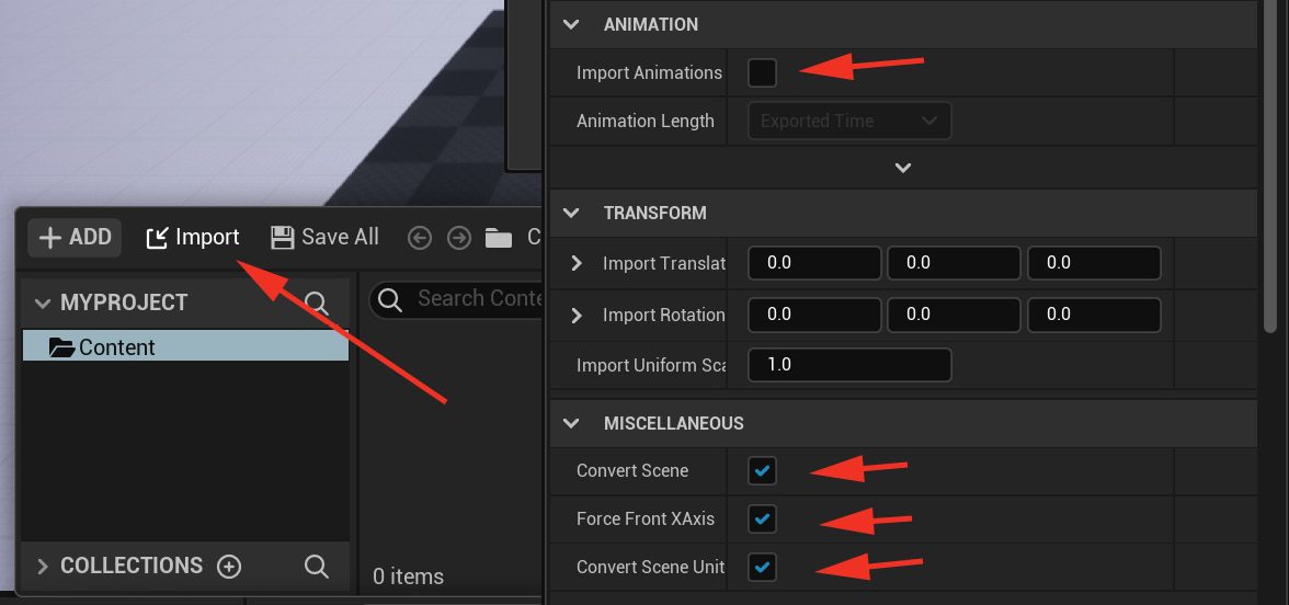
Figure 15.6 – Robot import settings
To double-check whether everything has been imported correctly, double-click the Robot Drone SKELETON file to open it, as shown in Figure 15.7:
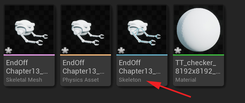
Figure 15.7 – Checking the import part 1
If everything is correct, when you select the root bone, in my case, Root_Robot, the position and scale transforms should be 0.0, 0.0, 0.0 and 1.0, 1.0, 1.0, respectively.
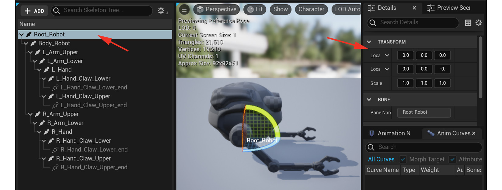
Figure 15.8 – Checking the import part 2
Our Robot Drone is now imported. Next, let's create the Control Rig.
Creating the Control Rig controllers
Just like we covered in Creating the Control Rig node on the Alien Plant in Chapter 14, Making a Custom Rig for Our Alien Plant with Control Rig, as shown in Figure 14.9, in Content Drawer, right-click on the Skeletal Mesh object and select Create Control Rig, as shown in Figure 15.9:
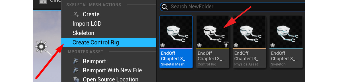
Figure 15.9 – Control Rig created
Double-click the Control Rig object to open up the Control Rig interface.
Let's think about what controllers we need for our Robot Drone. Our Robot Drone needs the following:
- A root controller that moves the entire rig
- A controller that moves the body and is the parent of the arm controllers
- IK controllers for the arms
- Controllers for controlling the two claws on each hand
Now, let's create the controllers we need to drive our Robot Drone. This is done in the same way we covered in the Creating basic Control Rig controllers section in Chapter 14, Making a Custom Rig for Our Alien Plant with Control Rig, so I'll be going through these steps in less detail here:
- Right-click in an empty spot in the Rig Hierarchy panel and select New | New Control, as shown in Figure 15.10:
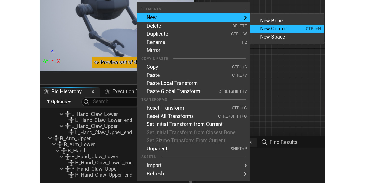
Figure 15.10 – Creating a new controller
- In the Details tab, in the Shape Properties section, set the new controller to Circle_Thick. Set Shape Transform's Scale to about 8.0. This will be the main root controller, as shown in Figure 15.11:
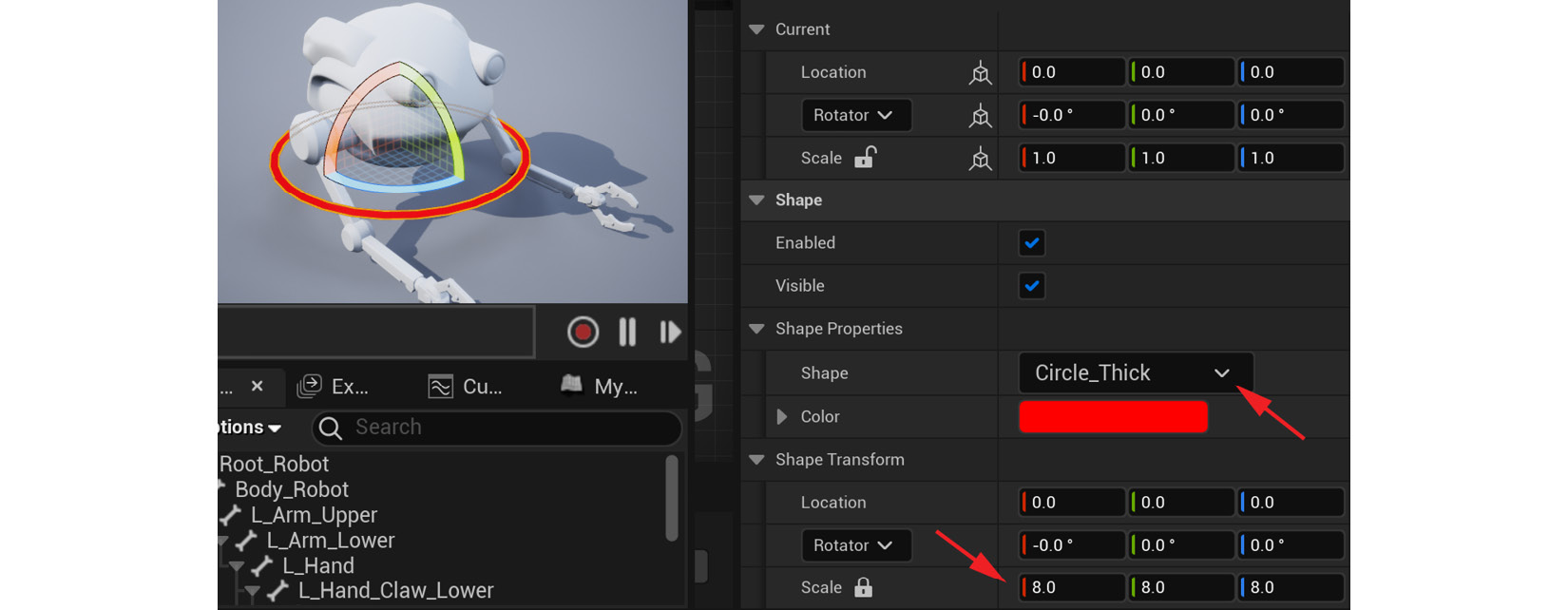
Figure 15.11 – Creating controller options
- Right-click again in an empty spot and create a second controller, but this time set Shape as Box_Thick and Scale to 4.0. This will be the controller for the body of the robot:
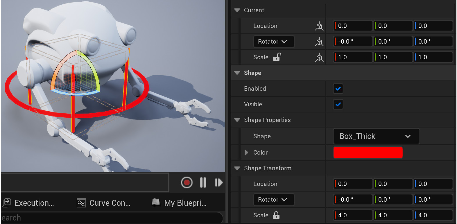
Figure 15.12 – Creating a second controller
- Now select this second controller with the Box_Thick shape, right-click on it, and select Duplicate.
- Set Scale of the new Box_Thick controller to 1.0. This will be the controller for one of the hands.
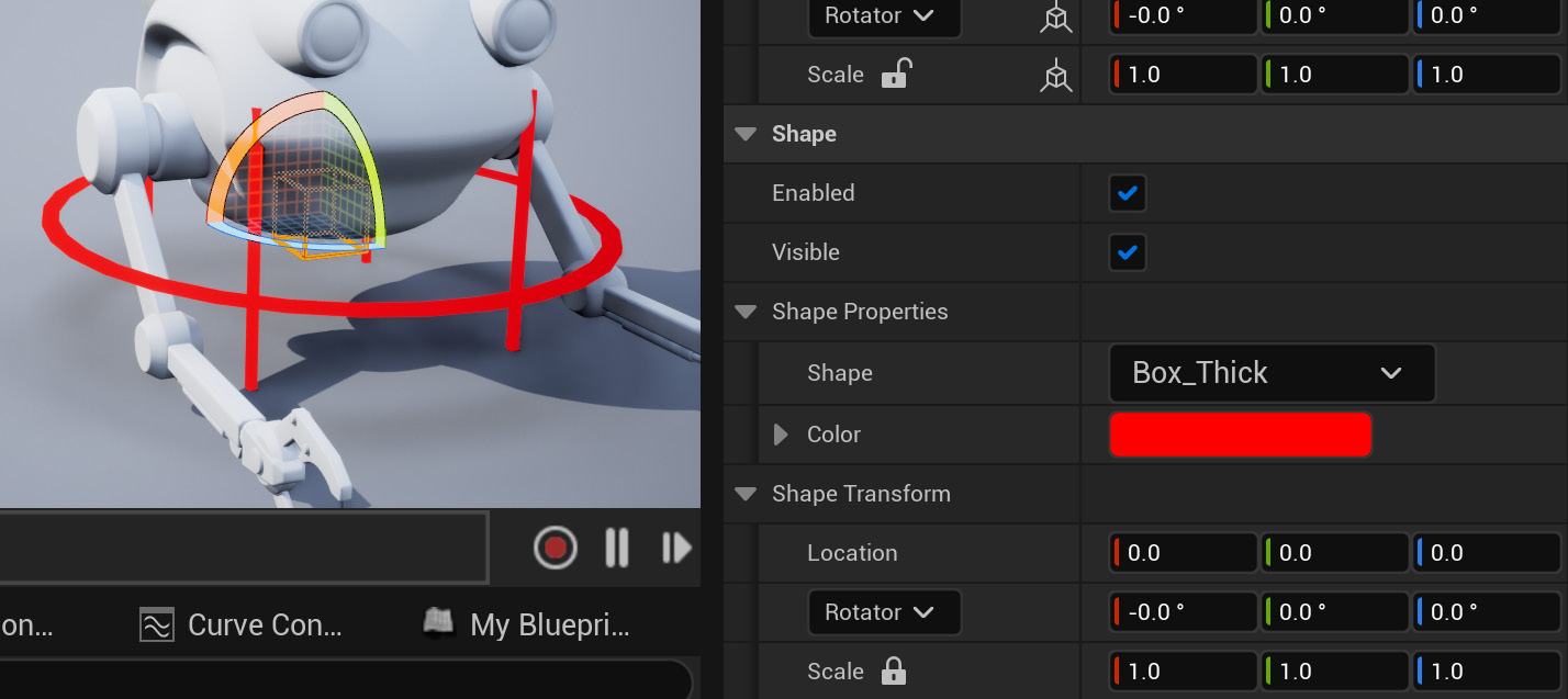
Figure 15.13 – Creating a third controller
- Right-click and select Duplicate for this smaller Box_Thick Shape controller three more times, so you have a total of four of these. This will be one for each hand, and one for each elbow (pole vector).
- Rename the controllers with descriptive names like the ones on the right-hand side of Figure 15.14:
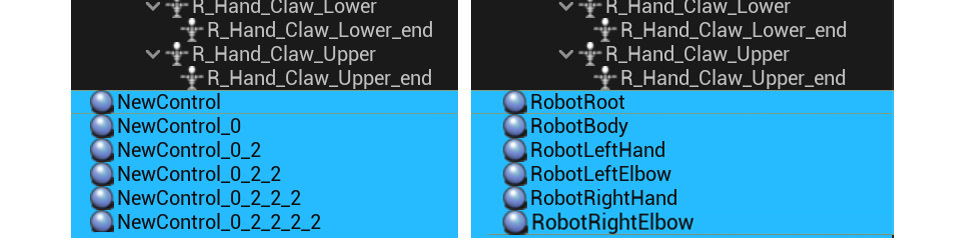
Figure 15.14 – Renaming controllers
Next, we'll create the controllers for the claws on the hands in a slightly different way so we can see what they will look like in the final position.
- Instead of right-clicking in an empty spot in the Rig Hierarchy window, right-click on the L_Hand_Claw_Lower bone and select New | New Control. This will create the controller on the position (and as a child) of the bone. Now we can see what the controller will look like in its final position.
- Change Shape to QuarterCircle_Thick and Scale to 2.0; rename it LeftLowerClaw.
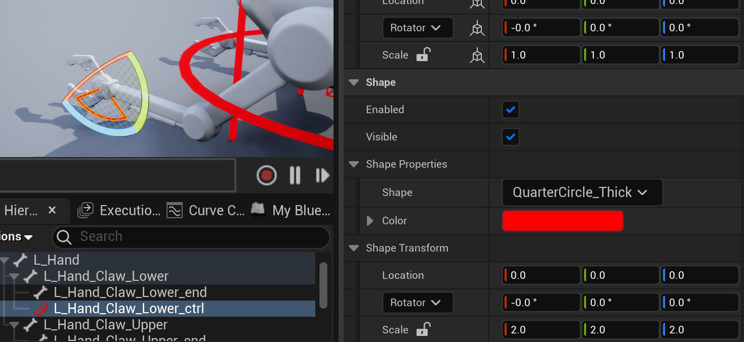
Figure 15.15 – Claw controller
- In the same way, right-click to create a controller on top of the L_Hand_Claw_Upper bone. Change Shape to QuarterCircle_Thick and Scale to 2.0, plus change the color to blue (to visually stand out from the other claw controller) by clicking on Color and using the color selector, as shown in Figure 15.16:
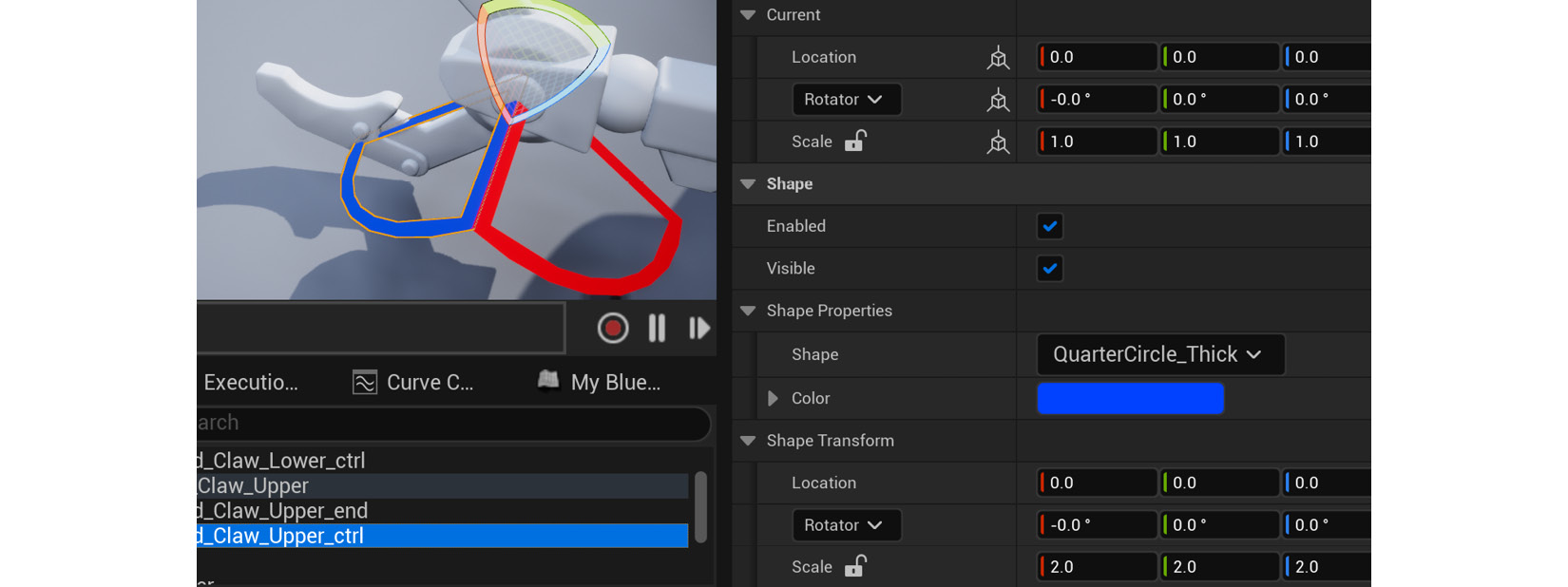
Figure 15.16 – Claw controller upper changed to blue
- Rename this controller LeftUpperClaw.
- Repeat this process for the claws on the right hand.
- Once all four claw controllers have been created, press Ctrl + left-click to select all four of them. Right-click to select one of the claw controllers and choose Unparent.
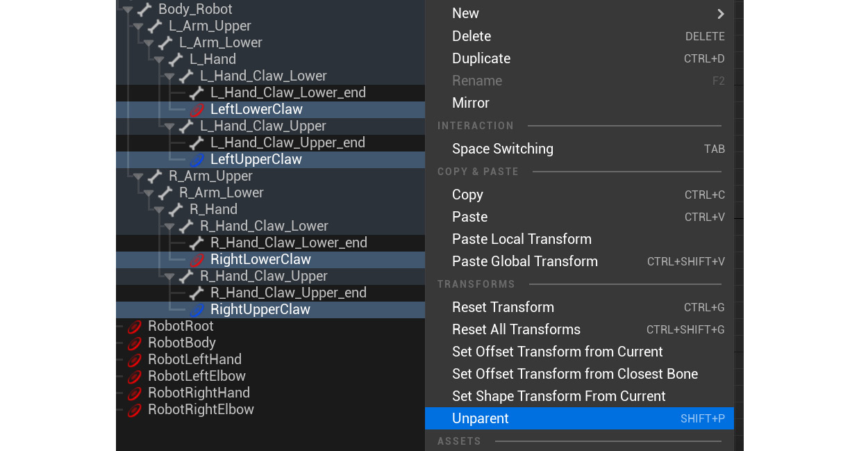
Figure 15.17 – Unparenting claw controllers from the bones
The claw controllers will be unparented from the bones and move to the bottom of the Rig Hierarchy window with the other controllers.
We should now have something as in Figure 15.18:

Figure 15.18 – Controllers result
We have now created all the controllers we need for our Animation Rig. Next, we'll organize them in the correct hierarchy.
Ordering the control objects in the correct hierarchy and linking them to joints
In this section, we need to organize our rig controllers in the correct hierarchy. Just like with all our parent/child hierarchies in our Animation Rigs, the hierarchy needs to be parented in the right order, so our rig works correctly.
Controller hierarchy
Like with our Alien Plant Control Rig, we need to figure out how we want our hierarchy to work.
Firstly, we want an overall root controller (RobotRoot) that can move our entire Animation Rig if we need to. That needs to be at the top of the hierarchy and the parent of everything in the Animation Rig.
Secondly, we want the body controller (RobotBody) as the child of the root controller. We just need to left-click to select and hold the mouse button to drag the RobotBody controller on top of the RobotRoot controller, as shown in Figure 15.19:

Figure 15.19 – Parent body controller to root controller
Following that, RobotLeftHand, RobotLeftElbow, RobotRightHand, and RobotRightElbow should be the children of the RobotBody controller, as shown in Figure 15.20:

Figure 15.20 – Parent hand controller to body controller
Finally, the claw controllers should be the children of their respective hands, as shown in Figure 15.21:

Figure 15.21 – Parent claw controller to hand controller
Our controllers are now in the right hierarchy, but they do not line up with our bones yet. Next, we'll do that like we did in the Positioning the controllers on the joints section in Chapter 14, Making a Custom Rig for Our Alien Plant with Control Rig.
Positioning the controllers to line up with the bones
To line up the controllers to the bones, we need to copy the bone transforms and paste them onto the controllers. Like with the Alien Plant, we need to start at the top of the hierarchy with the parents and work our way down. We'll leave the RobotRoot controller at the origin of the scene.
Let's line up the RobotBody controller first since it's next in the hierarchy:
- Right-click on the Body_Root bone and select Copy.

Figure 15.22 – Copy transform
- Right-click on the RobotBody controller and select Paste Global Transform, as shown in Figure 15.23:
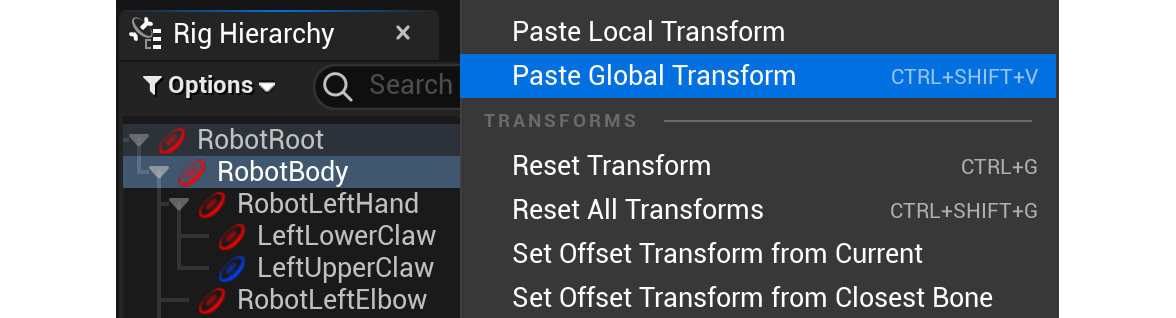
Figure 15.23 – Paste transform
- Right-click on the RobotBody controller again and select Set Offset Transform from Current, as shown in Figure 15.24:
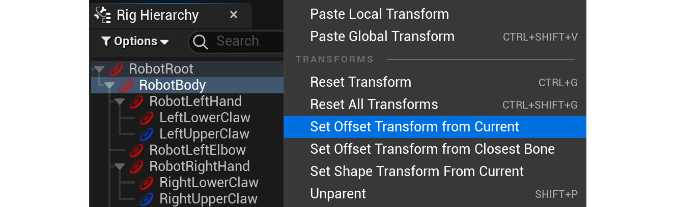
Figure 15.24 – Setting a transform
- Now, work your way down the entire controller hierarchy until all the controllers are lined up with their respective bones. The elbow controllers should line up with lower arm bones. The end result should be something like shown in Figure 15.25:
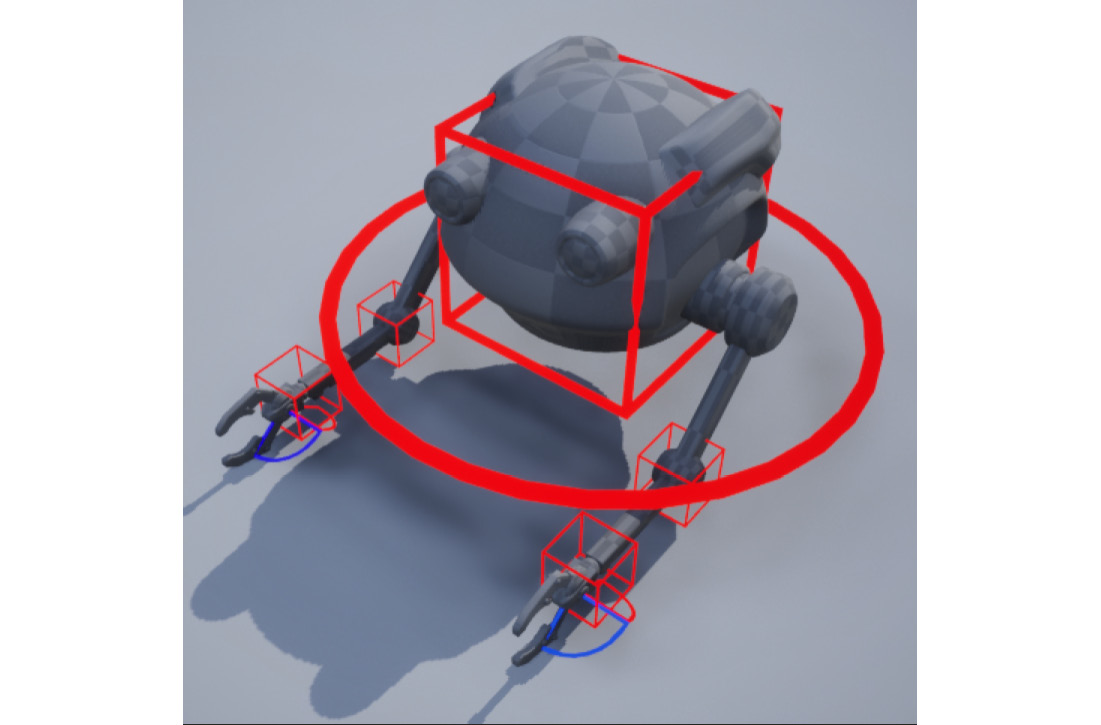
Figure 15.25 – Control Rig result
- In the Viewport, select RobotLeftElbow, then hold Ctrl + left-click to select RobotRightElbow. Select the Move tool at the top of the Viewport and move them slightly down and slightly back, as shown in Figure 15.26:
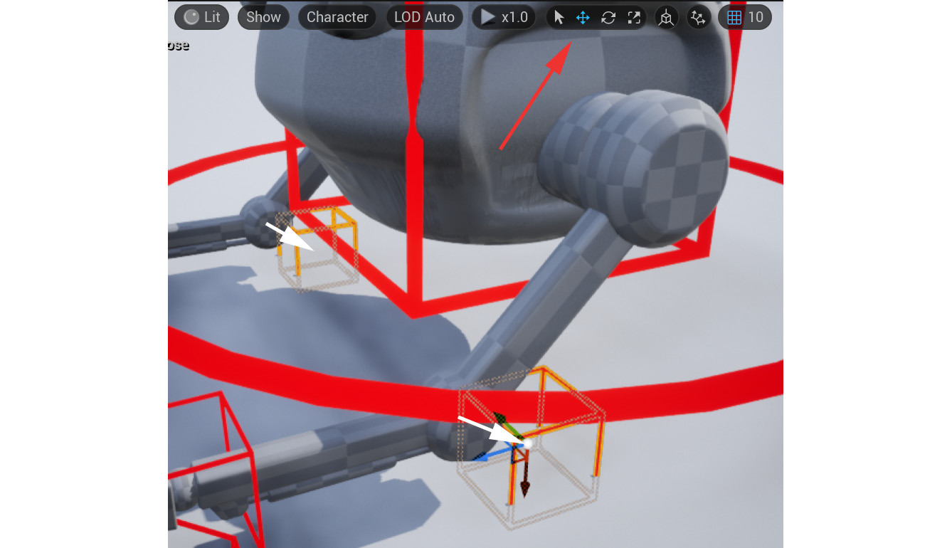
Figure 15.26 – Elbow pole vector controller position
We do this since we want the elbows to point toward them, so they need to be a bit offset. This is how IK pole vector controllers work. Later in this chapter, you will see this in action.
- With both the elbow controllers still selected, right-click in the Rig Hierarchy window and select Set Offset Transform from Current.
We have now created and positioned all the controllers we'll need for our Robot Drone Animation Rig. Next, we need to link the bones to the controllers in Rig Graph.
Linking bones to controllers in Rig Graph
This first part of the process is the same as what we did for the FK setup in the Controlling the Alien Plant skeleton with the controllers section in Chapter 14, Making a Custom Rig for Our Alien Plant with Control Rig:
- Start by dragging the bone object, the Root_Robot bone, into the Rig Graph window and setting it to Set Bone.
- Drag the RobotRoot controller into the Rig Graph window and set it to Get Control.
- Connect the Transform socket from RobotRoot's Get Transform to Root_Robot's Set Transform node.
- Now do the same for the Body_Robot bone and the RobotBody controller. Also connect the Execute sockets, as shown in Figure 15.27:

Figure 15.27 – Body rig
Now, we will do something a bit different from the Alien Plant rig. This is purely to help us organize more complex rigs visually more easily in Rig Graph.
- Press Ctrl + left-click to select all the Set Transform - Bone and Get Transform - Control for the root and body, so four in total. Press C on the keyboard to create a comment. This is just a display box around those items, as shown in Figure 15.28.
- Rename the Comment box Body Controls.
We now know at a glance that these nodes in the rig control the main body of our Robot Drone.
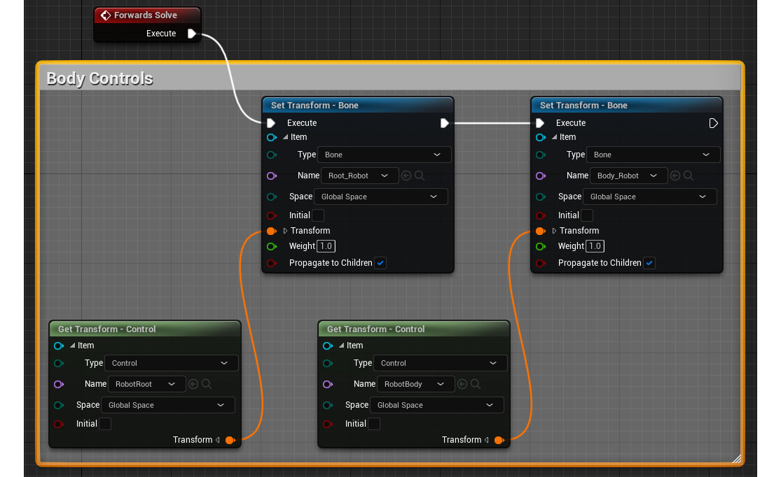
Figure 15.28 – Body rig comment
Next, we'll create the setup for the left hand and the two claws.
- Same as with the body controls, drag the Lhand, L_Hand_Claw_Lower, and L_Hand_Claw_Upper bones into Rig Graph and set to Set Bone. Then, drag the RobotLeftHand, LeftLowerClaw, and LeftUpperClaw controllers into Rig Graph and set it to Get Control. Link up the respective Transform and Execute node sockets.
- Select all six of these new nodes in Rig Graph and press C to add a comment. Name it Left Hand, as shown in Figure 15.29.
Now, all the controls for the left hand of the Robot Drone are grouped together. Adding these comments does not change the functioning of the Animation Rig. It is just a visual tool to quickly make sense of a more complex rig. This rig is not complicated, but in the future, you might do much more complex setups than this.
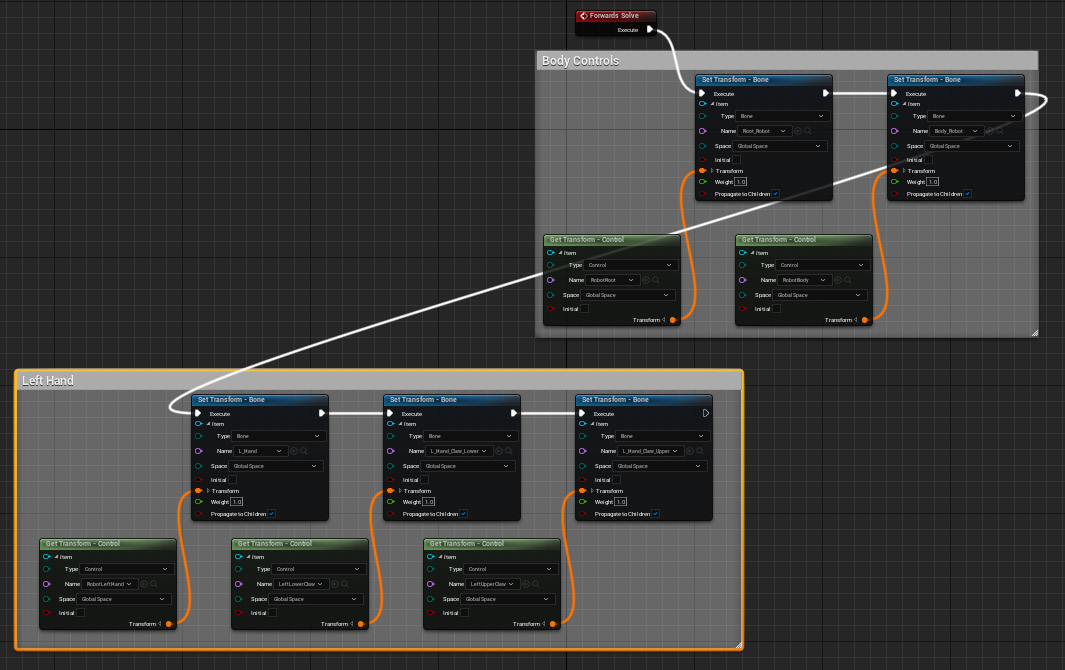
Figure 15.29 – Body rig and left-hand comments
- Repeat this process for the right-hand controls and bones, and also comment them into a group and name it Right Hand, as shown in Figure 15.30:
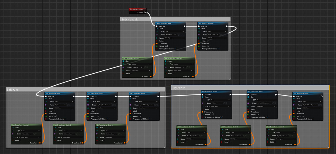
Figure 15.30 – Body rig and left- and right-hand comments
We have now set up the standard FK parts of our Animation Rig, the body and both hands with claws. Now we can set up the arms with IK.
Creating an IK controller and testing the whole rig
Before we set up the IK controls, we need to get a few bits of information from our arm skeleton. This is going to be used later to set up the orientation of our IK control.
Getting bone orientations of our arm bones
In the Rig Hierarchy window, right-click on the L_Arm_Lower bone and select Control Bone Transform, as shown in Figure 15.31:
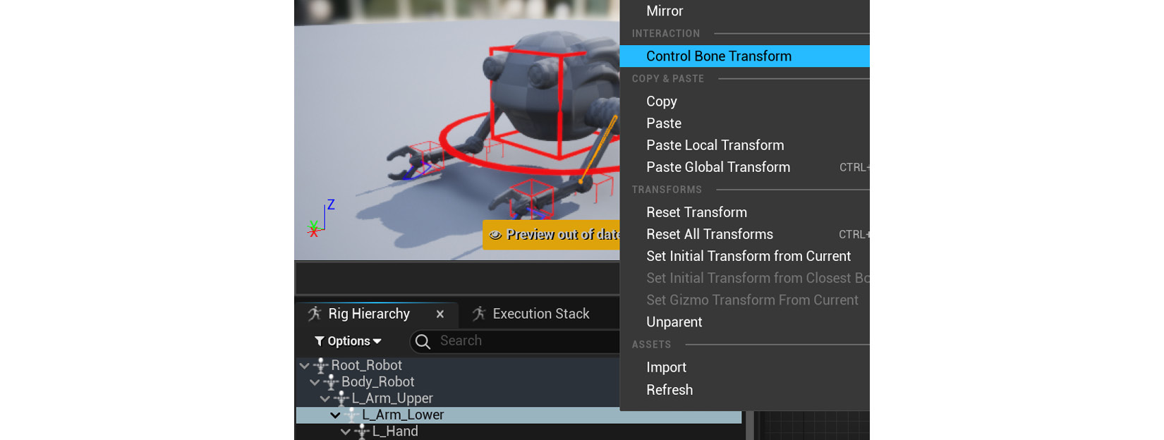
Figure 15.31 – Control Bone Transform
This will display the local transform of the bone. Make sure it's set to Local Space and select Move, as shown in Figure 15.32:

Figure 15.32 – Axes primary and secondary
Notice that the Z axis (blue Z arrow) is pointing directly down the arm toward the hand. Note this direction down as +Z (if the blue Z-axis arrow were pointing in the opposite direction but along the same axis to the hand, it would have been -Z).
This +Z value is what we will use later as the primary IK axis. Now note in what direction axes the elbow is mainly pointing (in this case, toward the ground). This would be the +X axis along the red X arrow. This +X value is what we will use later as the secondary IK axis. Note this down too.
These primary and secondary values we note down now will simply tell the IK controller in what direction our elbow bends when we input them later in this chapter. Now that we have these values, we can build our IK setup.
Setting up an IK controller
To set up the IK controller, there's a Basic IK node in Control Rig that takes care of everything. Let's create it:
- In the Rig Graph window, right-click in an empty space underneath the Left Hand comment group. This will bring up a menu of all the possible nodes that could be added to Rig Graph. In the Search bar at the top, type in ik, then select Basic IK, as shown in Figure 15.33:
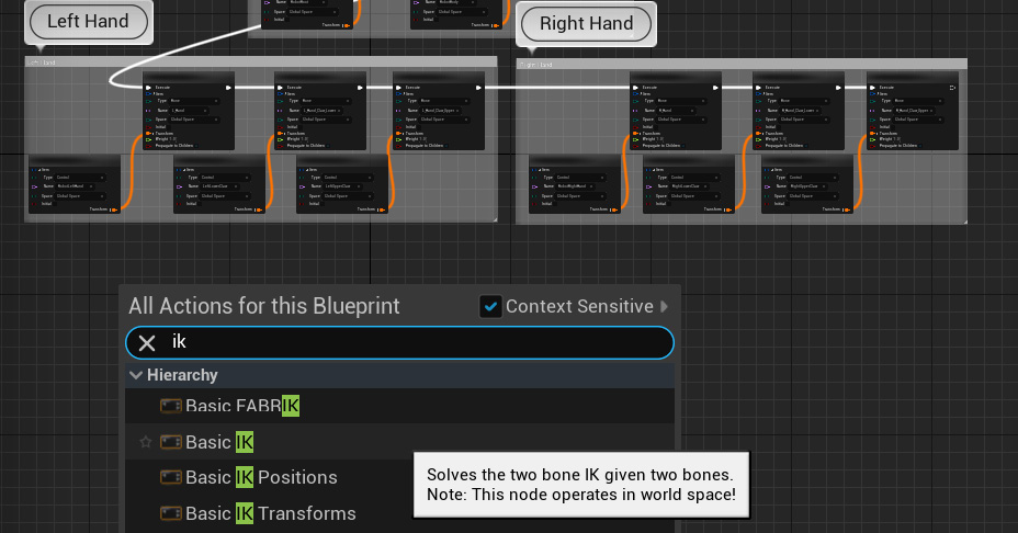
Figure 15.33 – Creating a Basic IK node
This creates the Basic IK node shown in Figure 15.34:
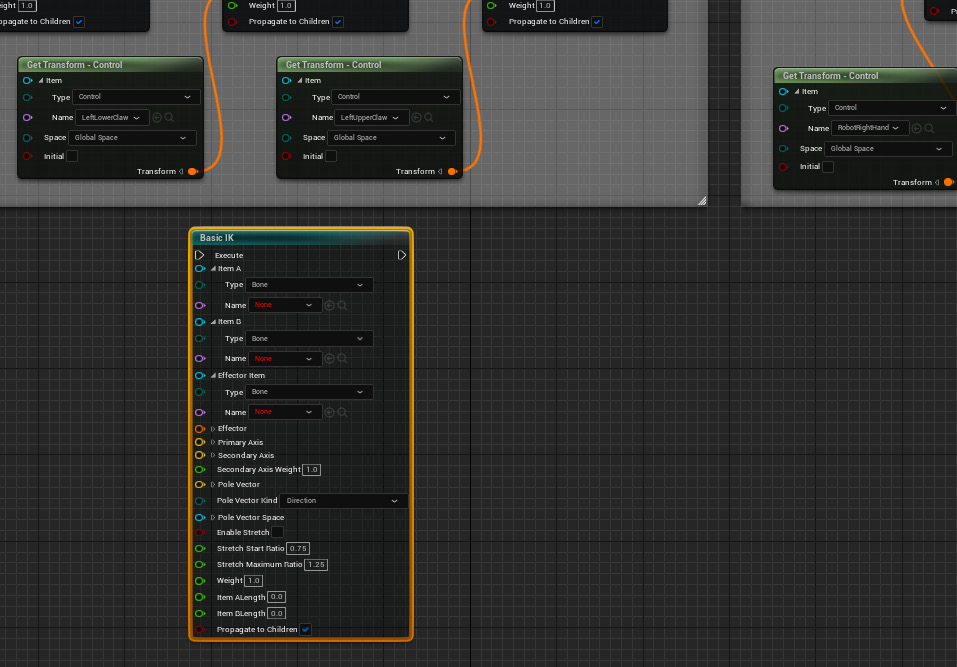
Figure 15.34 – Basic IK node
In the Basic IK settings, there are Item A, Item B, and Effector Item. These are the three bones that will be in our IK setup:
- Item A: Parent or beginning of the IK chain (L_Arm_Upper)
- Item B: The bone that bends like an elbow or knee (L_Arm_Lower)
- Effector Item: Where the IK ends, or in other words, where it's trying to reach (L_hand)
- From the drop-down menu settings on the Basic IK node, make sure Type is set to Bone, and then select L_Arm_Upper for Item A, L_Arm_Lower for Item B, and L_Hand for Effector Item under the Name drop-down menu, as shown in Figure 15.35:
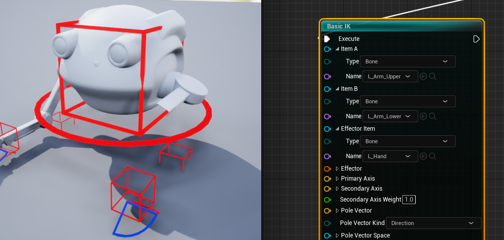
Figure 15.35 – Basic IK node bone select
Remember to connect the Execute socket from the last Set Transform - Bone to the Basic IK Execute socket. Otherwise, Basic IK won't be activated. The robot's left arm will look broken at this point. No need to worry about that since we need to set up the rest of the settings before it will function correctly.
Next, we want our RobotLeftHand controller to be the thing that the IK aims for. Just like it controls the L_Hand bone position, it can also control the Effector position.
- Drag and link the Transform socket connection from RobotLeftHand Get Transform - Control to the Effector socket on the Basic IK node. Now it splits and drives both the L_Hand bone and Basic IK Effector, as shown in Figure 15.36:
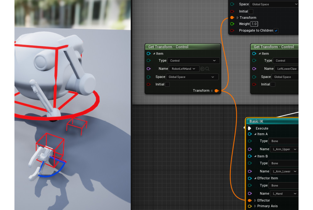
Figure 15.36 – Get Transform to Effector
Now we'll use the values we got from the Getting bone orientations of our arm bones section of this chapter to input the correct values under the primary and secondary axes.
Expand the Primary Axis and Secondary Axis settings by left-clicking on the small arrow in front of their names. The value we noted down for Primary Axis was +Z, so set Z to 1.0 (1.0 = plus and -1.0 = minus). Make the rest 0.0.
The value we noted down for Secondary Axis was +X, so set X to 1.0. Make the rest 0.0, as shown in Figure 15.37:
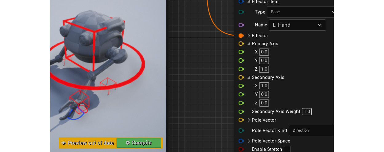
Figure 15.37 – Primary and secondary axes
The arm will still look broken, but less so. This is because the pole vector controller (the direction that the elbow points) is set to be at the origin of the scene by default. We created the RobotLeftElbow and RobotRightElbow controllers for this reason, so now, let's hook up the RobotLeftElbow controller to our Basic IK settings.
- Drag the RobotLeftElbow controller into Rig Graph from the Rig Hierarchy panel, set to Get Control, expand the Transform socket with the little arrow, then connect the yellow Translation socket to the yellow Pole Vector socket, as shown in Figure 15.38.
This is because pole vectors are not influenced by rotation or scale. They are merely points in space that the elbow or knee can point to.
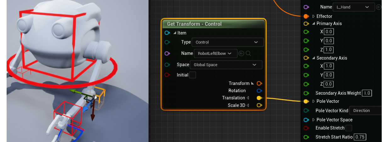
Figure 15.38 – Pole vector
The arm should not look broken anymore. The IK setup for the left arm should now be complete. Next, let's test the IK setup.
Testing the IK setup
You can now test the left arm IK by moving the RobotLeftHand and RobotLeftElbow controllers. Remember not to undo after moving the controllers in the Viewport; when wanting to return them to the original positions, press Compile instead. If you undo, it will undo the work you just did on your rig setup.
Particularly look how the elbow points to the RobotLeftElbow controller when you move it, as shown in Figure 15.39:
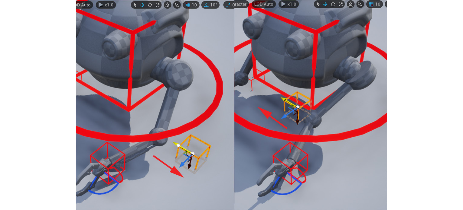
Figure 15.39 – Pole vector test
Hopefully, this will help you to understand what a pole vector is when you see it in action. Move and rotate RobotLeftHand and see that the arm bones automatically bend to always reach the hand. This is IK in action. You can also select the claw controllers and rotate them as a test.
If you're happy with how everything works, repeat this process to create IK controls on the right arm. Test it all, as shown in Figure 15.40, and save your UE project once you're done:
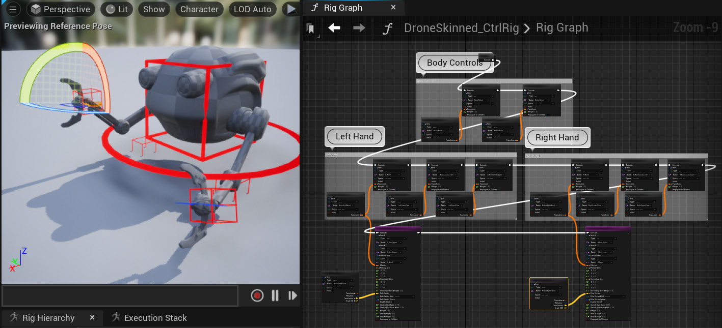
Figure 15.40 – Complete Animation Rig tested
We have provided the completed Control Rig for the Robot Drone in the final project file, which can be downloaded from here with installation instructions: https://github.com/PacktPublishing/Unreal-Engine-5-Character-Creation-Animation-and-Cinematics/tree/main/FullFinalUE5Project
The example Control Rig is under Content/RobotDroneControlRig.
Your Robot Drone Animation Rig is now complete.
Summary
In this chapter, we learned how to correctly export our Robot Drone from Blender and import it into UE. We learned what IK is. We also built a basic FK rig for the body controls and then set up IK controls for our Robot Drone arms on the same Animation Rig.
If you can set up basic FK and IK on an Animation Rig, you're well equipped to set up almost any basic character rig and can achieve a lot. Rigging can be very complicated on complex rigs, but these two basic building blocks of basic FK and IK setups are at the core of it all.
In the next chapter, we will do some animation on these Animation Rigs we created.