
3
Lights, Sound, and Motion with M5Stack
In the previous chapter, we learned about the various units that extend the M5Stack Core operational functions. You learned about the various ports that allow units to attach to the M5Stack Core. You learned how personalized wiring for creating a push button switch can aid the construction of such an electrical device using discrete electronic components. Chapter 2 also introduced you to the approach of using a four-wire jumper harness for attaching units to the M5Stack Core. Further, you learned how to program the M5Stack Core using the UIFlow Blockly code software to operate various units and design basics and received overview information on this software. The new knowledge obtained in Chapter 2 will allow you to learn about and use the external and internal hardware of the M5Stack Core for creating interactive and engaging electronic devices. In this chapter, you will explore M5Stack Core external and internal hardware for lights, sound, and motion applications. The external and internal hardware are electronic circuits such as an external vibration motor, the internal speaker, and the side RGB LED bars. You will use the UIFlow Blockly code to investigate the function of these external and internal hardware electronic circuits.
By the end of this chapter, you will know how to perform the following technical tasks with M5Stack external and internal hardware:
- Draw a typical M5Stack hardware block diagram
- Create and code a haptic controller UIFlow-based device
- Create and code a tone generator
- Create and code an electronic flashlight
- Create and code an emergency flasher
- Create and code an interactive emoji
In this chapter, we are going to cover the following main topics:
- Introducing M5Stack Core hardware
- Using the M5Stack Core vibration motor unit
- Using the M5Stack Core speaker
- Coding an M5Stack Core RGB LED flasher
- Coding an M5Stack Core interactive emoji
Technical requirements
To engage with the chapter’s learning content, you will need the M5GO IoT starter kit to explore the internal/external hardware electronics and software coding of your first basic application. A littleBits vibration motor, the proto module, and a LEGO mounting plate may be purchased to build a Homebrew haptic device. The UIFlow code block software will be required to build and run the M5Stack Core internal and external device applications.
You will require the following:
- The M5Stack Core vibration motor unit
- The M5Stack Core controller
- The M5GO IoT starter kit
- UIFlow code block software
- A littleBits vibration motor
- The proto module
- A LEGO brick adaptor
- A USB-C cable
Here is the GitHub repository for software resources: https://github.com/PacktPublishing/M5Stack-Electronic-Blueprints/tree/main/Chapter03.
Introducing M5Stack Core hardware
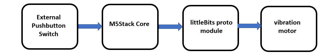
The M5Stack Core is supported by several internal hardware circuits. With these internal hardware circuits, you can create visual interactive devices that engage the human senses. You can access these internal hardware circuits using Blockly code. The internal hardware circuits you will engage with in this chapter are the amplifier speaker, the RGB LED bar, and the pushbutton switches. Besides these internal hardware circuits, you will build and code a mountable vibration motor. The mountable vibration motor provides a sneak preview of Chapter 5. In this hardware introduction, you will be introduced to electrical circuit interfacing by building the mountable vibration motor. To introduce the mountable vibration motor, here is a block diagram representation of the external hardware device:

Figure 3.1 – Mountable vibration motor block diagram
As shown in Figure 3.1, each electronic component is represented by a block. The control signals flow from each block in the direction of left to right. The arrows represent the control signals flowing between the individual components. With this graphical approach, you can draw the hardware architecture of any wearable or electronic controller concept for the M5Stack Core. Here is another example illustrating the drawing of a block diagram:

Figure 3.2 – RGB LED component block diagram
Figure 3.2 shows the RGB LED component, the electronic circuit symbol, and its block diagram. As you can see, the only elements captured in the block diagram are the input and output signal connections. Therefore, the purpose of the block diagram is to show the data or the signal flow between the interconnected hardware components. Thus, the block diagram shows the interconnected relationships between hardware components.
Interactive quiz 1
Using Figure 3.1, draw a block diagram showing an external pushbutton switch operating the vibration motor using the M5Stack Core.
Congratulations, you now have knowledge of drawing block diagrams for the M5Stack Core. You will use this knowledge for the projects in this chapter. You will now explore the vibration motor unit hardware using the M5Stack Core and the UIFlow Blockly code.
Using the M5Stack Core vibration motor unit
You can use the M5Stack Core to operate a vibration motor. The vibration motor unit has a weight that is offset and mounted to its rotating shaft. Figure 3.3 shows an example of the M5Stack Core vibration motor, whose shaft has an attached metal-eccentric weight:

Figure 3.3 – M5Stack Core vibration motor unit
In general, a wide range of products use a vibration motor unit to provide physical stimuli to the user. This physical sensory perception or haptic feedback allows an individual to be totally immersed in the product through a human interaction experience. You can easily operate an M5Stack Core vibration motor using the UIFlow Blockly code software. In the next section, you will learn how to attach a vibration motor to the M5Stack Core. Further, you will learn how to program the M5Stack Core to operate the vibration motor.
Attaching the M5Stack Core to the vibration motor unit
The first step of programming the M5Stack Core to operate the vibration motor is the attachment of the electromechanical component to the programmable unit. To operate the vibration motor, you will attach the programmable device to the M5Stack Core using a four-wire jumper harness. You will use port B of the M5Stack Core to attach the vibration motor to the M5Stack Core. Figure 3.4 shows the attachment of the four-wire jumper harness between the vibration motor and the M5Stack Core. The four-wire jumper harness has a color code scheme consisting of black, red, white, and yellow. You can verify that the jumper harness is correctly attached between the M5Stack Core and the vibration motor by the black wire located on the left side:

Figure 3.4 – Vibration motor unit attached to the M5Stack Core
You are now ready to program the M5Stack Core to operate the vibration motor using the UIFlow Blockly code software.
Programming the M5Stack Core to operate the vibration motor unit
You will use the UIFlow Blockly code software to program the M5Stack Core to operate the vibration motor. You will take a USB-C cable and insert it into the M5Stack Core’s equivalent port. You will take the other end of the USB-C cable and insert it into your UIFlow Blockly code development machine. Your M5Stack Core should be turned on. You will press the middle button to configure your M5Stack Core to be in USB mode. Figure 3.5 shows the M5Stack Core operating in USB mode.
Note
Refer to Chapter 1, in the Communicating with the M5Stack Core section. to configure the programmable controller for USB mode.

Figure 3.5 – The M5Stack Core operating in USB mode
You will select from the appropriate Blockly code blocks bin to build the vibration motor application shown in Figure 3.6:

Figure 3.6 – Vibration motor UIFlow Blockly code
Interactive quiz 2
What effect would switching the binary values in the UIFlow Blockly code shown in Figure 3.6 have on the vibration motor?
As the code is running on the M5Stack Core, the B port turns on and off every 3 seconds. The vibration motor initially turns on for 3 seconds. After the 3 seconds have expired, the vibration turns off and remains in that state for the same amount of time. When the motor is in the on state, the electromechanical component will vibrate, thus providing mechanical motion. Congratulations! You have successfully programmed the M5Stack Core to operate a vibration motor. With our success in operating the M5Stack Core vibration motor, let us take our knowledge of UI layout design and block diagrams to build a mountable vibration motor unit using littleBits electronic modules.
Building a mountable vibration motor unit
The concept behind this project is to create a mountable vibration unit using littleBits electronic modules and a LEGO brick adapter. Figure 3.1 shows the block diagram for the prototype unit. The littleBits mountable vibration unit assembly diagram for attachment of the proto and vibration motor modules is shown in Figure 3.7. You will use the assembly diagram created from the block diagram to attach the littleBits electronic modules together:

Figure 3.7 – Mountable vibration motor unit assembly diagram
To ensure the littleBits electronic modules are electrically stable, a LEGO brick adaptor is used. Figure 3.8 illustrates the LEGO brick adaptor attached to the proto and vibration motor electronic modules:

Figure 3.8 – LEGO brick adaptor attached to the mountable vibration motor unit
With the attached littleBits electronic modules assembled, you will wire the proto module to the four-wire jumper harness using the electrical wiring diagram shown in Figure 3.9. As illustrated in Figure 3.9, individual wires are used to make electrical extensions between the proto module and the four-wire jumper harness. These electrical extensions provide wire routing convenience for the mountable vibration motor. You can see that the vibration motor is magnetically attached to its snap leg. There are two small magnets on each side of the snap leg. The vibration motor will be safely secured to the snap leg illustrated in Figure 3.9.
Interactive quiz 3
With a digital voltmeter, what voltage would be sourced (measured) from the M5Stack Core’s B port?

Figure 3.9 – Mountable vibration motor unit electrical wiring diagram
You will attach the complete unit to the back of the M5Stack Core using the LEGO brick adaptor. You will snap the LEGO brick adaptor to the back of the M5Stack Core by aligning the studs appropriately. Figure 3.10 shows the mountable vibration motor unit attached to the M5Stack Core. Once the mountable vibration motor unit is attached, the final step of the project is to write the operational Blockly code.

Figure 3.10 – The LEGO brick adaptor attached to the M5Stack Core
Programming the M5Stack Core to operate the mountable vibration motor unit
You will start the programming process of operating the mountable vibration motor unit using the M5Stack Core by electrically connecting the two devices with a four-wire jumper harness. You will take a four-wire jumper harness and attach the M5Stack Core and the mountable vibration unit together, as shown in Figure 3.10. Next, you will make the mountable vibration motor unit interactive by creating the UI layout as shown in Figure 3.11:

Figure 3.11 – UI layout for mountable vibration motor unit
You can make the mountable vibration unit interactive by pressing the A and B pushbuttons on the M5Stack Core. You will program the M5Stack Core A button to allow the mountable vibration motor unit to turn on. Conversely, you will program the B button to turn off the mountable vibration motor unit. You will use the Blockly code program shown in Figure 3.12:

Figure 3.12 – Interactive mountable vibration motor unit Blockly code
Attach your M5Stack Core to the UIFlow development machine using a USB-C cable. Click on the Run button to download the interactive mountable vibration motor unit code to the M5Stack Core. Press the A button on the M5Stack Core to run the code. The littleBits vibration motor should be on. You stop the littleBits vibration motor by clicking the B button on the M5Stack Core. Figure 3.13 illustrates the mountable vibration motor in operational mode:
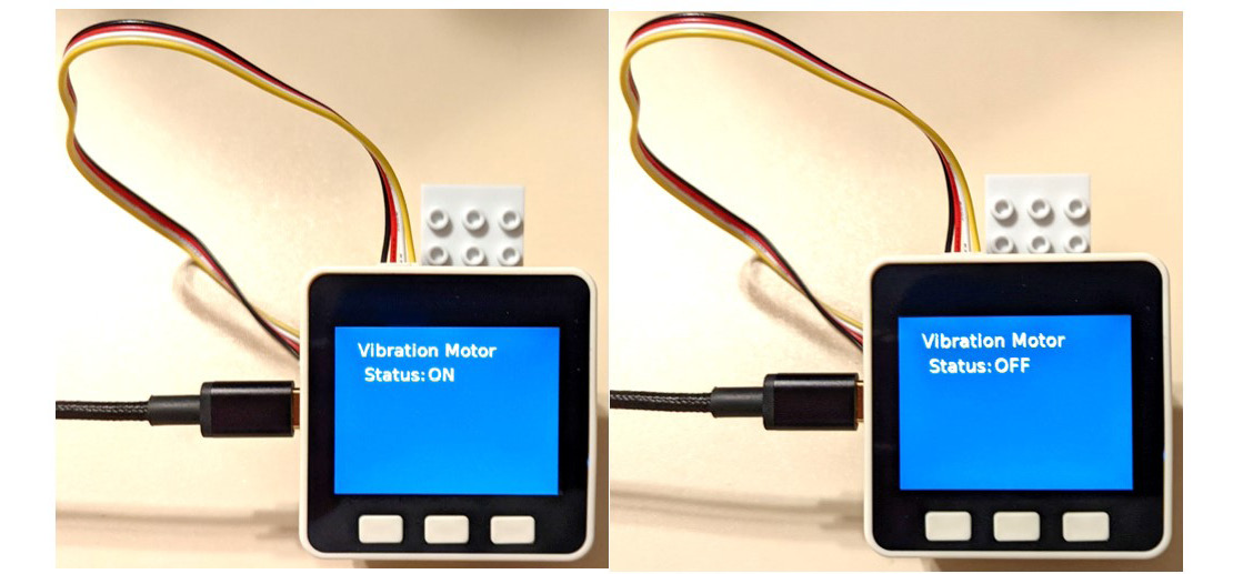
Figure 3.13 – An operational mountable vibration motor unit
Interactive quiz 4
What instructional UIFlow Blockly code block may be used to toggle the output state of the mountable vibration motor unit?
Congratulations, you have created a mountable vibration motor unit! Turn on the unit and hold it in your hand. The vibratory action produced is synonymous with haptic devices. Haptics technology allows the immersion of the user with an object through touch perception. Hand video controllers use a vibration motor to create an immersion experience between the gamer and the physical stimulus of the virtual world they are engaged in. You will explore the M5Stack Core’s internal speaker in the next section.
Using the M5Stack Core speaker
The M5Stack Core speaker allows the programmable unit to be transformed into a portable creative sound generator. The M5Stack Core speaker is driven by a powerful 3W class D amplifier. The benefit of using this type of amplifier is its efficiency. Theoretical class D amplifiers have an operational efficiency of 100%. Typically, a class D amplifier has an efficiency of 90%. This high-efficiency rating is achieved by switching the amplifier’s output transistors instead of driving them linearly. A pulse width modulation (PWM) signal effect is created, thus reducing the output transistors’ thermal dissipation. Further, this output switching produces a high voltage and current amplification signal. With a reduction in thermal dissipation, the efficiency of the output transistors driving a speaker is highly effective. Figure 3.14 shows a block diagram of the M5Stack Core speaker-amplifier circuit:

Figure 3.14 – M5Stack Core speaker-amplifier block diagram
Figure 3.15 shows the electronic circuit schematic diagram for the M5Stack Core speaker-amplifier block diagram:

Figure 3.15 – M5Stack Core speaker-amplifier circuit schematic diagram
In reviewing the electronic circuit schematic diagram, you will notice an input coupling capacitor C43 with a capacitance value of 100nF. This C43 capacitor has an impedance value. This impedance value establishes the input alternating current (AC) resistance necessary to allow audio generator electrical sound to flow into the amplifier without signal reduction or attenuation. This impedance value is called capacitive reactance (Xc). You can calculate this equivalent AC resistance or impedance value with the following equation:

Figure 3.16 – Capacitive reactance equation
The variables are defined as such: f is the input signal frequency, c is the input capacitor value, π (pi), and Xc is the capacitive reactance in ohms. To illustrate how to use this equation, here is an example problem.
Determine Xc for the input capacitor shown in Figure 3.15. The input signal’s applied frequency is 1.8 kilohertz (kHz) or 1,800 Hz.
The solution steps are shown in Figure 3.17:

Figure 3.17 – Solution for the example problem
Therefore, the capacitive reactance for the M5Stack Core amplifier with a generated sound signal of 1,800 Hz is 885 Ω.
Interactive quiz 5
Using the solution steps shown in Figure 3.17, determine Xc for an M5Stack Core-generated sound signal of 100 Hz.
You now understand the type of amplifier that operates the M5Stack Core speaker. You also know the basic function of the class D amplifier, its block diagram configuration, and the equivalent electronic circuit schematic diagram. You have mathematical knowledge of calculating the capacitive reactance of an audio amplifier. In the next section, you will learn how to program the M5Stack Core to produce a basic sound. Further, you will learn how to make an interactive sound generator with a graphically displayed speaker icon.
Programming the M5Stack Core to produce a sound
You will start the programming process of producing a sound using the M5Stack Core by programming a basic warning alarm. You will operate the basic warning alarm by pressing the A button. The warning alarm will sound five times and stop. Figure 3.18 shows the warning alarm block diagram:

Figure 3.18 – The warning alarm block diagram
You will use the sound Blockly code blocks to program the M5Stack Core to produce an audible warning tone. Figure 3.19 shows the location of the sound code blocks within the UIFlow programming palette. The selected sound blocks will be added with the A button and the Wait code blocks to create a two-tone alarm.

Figure 3.19 – The sound code block palette
The UIFlow Blockly code that aligns with the warning alarm block diagram is shown in Figure 3.20. You will use these code blocks to program the M5Stack Core. Click the Run button with your mouse to run the Blockly code on the M5Stack Core.

Figure 3.20 – The warning alarm Blockly code
Once you have built the code in the UIFlow environment, a simple speaker message can be added to display on the M5Stack Core TFT LCD using a label. Figure 3.21 shows the UI label properties of the speaker message. As you can see, the label is somewhat placed in the middle of the M5Stack Core TFT LCD:

Figure 3.21 – The warning alarm M5Stack Core UI
With the Blockly code built and the UI designed, you can execute the Blockly code on the M5Stack Core by clicking the Run button with your mouse. Press the A button to hear a two-tone sound playing from the M5Stack Core speaker. Congratulations, you have successfully built a handheld warning alarm. You will now enhance the UI by adding a speaker icon to the M5Stack Core TFT LCD.
Interactive quiz 6
In reviewing the Blockly code shown in Figure 3.20, how can the interval time between tones be increased to 1 second?
Adding a speaker icon to the TFT LCD
You can make the speaker application TFT LCD appealing by adding an icon. The icon enhances the UI by visually identifying the operation of the programmed M5Stack Core. To add a speaker icon or picture to the M5Stack Core, drag the Image icon from the side panel and place it on the M5Stack Core’s UI manager. Figure 3.22 illustrates this action:

Figure 3.22 – Placing the Image icon onto the M5Stack Core UI manager
You will then configure the properties of the speaker label and the image. Figure 3.23 illustrates configuring the label and image properties.
Note
The .jpg or .png file extensions are acceptable formats for displaying images on the M5Stack Core TFT LCD.

Figure 3.23 – Configuring the label and image properties
The speaker icon is uploaded to the image from a stored location on your desktop personal computer or laptop computer’s hard drive. The imagePath field is the location of the stored speaker icon on your desktop personal computer or laptop computer’s hard drive. You will click the Reload image to upload the speaker icon to the image. Once completed, the speaker icon should be displayed on the M5Stack Core’s UI manager, as shown in Figure 3.24:

Figure 3.24 – The speaker icon displayed on the M5Stack Core’s UI manager
Here is the speaker icon displayed on an actual M5Stack Core. The Blockly code shown in Figure 3.20 may be used with this speaker icon-enhanced display:

Figure 3.25 – An M5Stack Core displaying a speaker icon
Congratulations, you have created an enhanced speaker application with a visually appealing TFT LCD. In this section, you have learned the basics of creating audible tones using the internal NS4148 3W Class D amplifier and speaker. In the next section, you will build a portable emergency flasher using the M5Stack Core’s internal RGB LED hardware.
Coding an M5Stack Core RGB LED flasher
The M5Stack Core has internal RGB LEDs that can be commanded by the ESP32 microcontroller. The RGB LEDs are of the SK6812 programmable family variant. The SK6812 is a smart control circuit that operates an LED. The smart control circuit and light-emitting circuit are packaged inside one programmable LED source. You can refer to Figure 3.2 for viewing the physical package, mechanical dimensions, and electronic symbol of the SK6812 RGB component. Another added feature of the SK6812 LED is the ability to emit a natural white light. Therefore, the SK6812 is an RGBW light-emitting component.
Note
Obtaining the natural white color requires a technique in color mixing of the RGB emitters. The following website provides information on obtaining white and various colors: https://txwes.libguides.com/c.php?g=978475&p=7075536.
The M5Stack Core uses two SK6812 LED bars. The SK6812 LED bar is located on each side of the M5Stack Core. Figure 3.26 shows the location of one SK6812 LED bar. There are five SK6812 LEDs wired together to make one LED bar. Therefore, the M5Stack Core uses 10 SK6812 LEDs to allow various light patterns to be created by you.

Figure 3.26 – An SK6812 LED bar
To create an RGB LED flasher, let us create a block diagram for the light-emitting switch device. The RGB LED flasher block diagram will consist of three components, a pushbutton switch, the ESP32 microcontroller, and the SK6812. Figure 3.27 illustrates the RGB LED flasher block diagram. You will use the block diagram to code the RGB flasher in the UIFlow Blockly code coding environment. The RGB LED flasher code will be programmed onto the M5Stack Core.

Figure 3.27 – M5Stack Core RGB LED flasher block diagram
Programming the M5Stack Core to operate the RGB LED as a flashlight
You will start the programming process of operating the IR remote unit using the M5Stack Core by obtaining the Blockly code blocks from the RGB code block palette. Figure 3.28 shows the various RGB Blockly code blocks available for the M5Stack Core. As you can see, there are seven unique Blockly code block instructions available for the M5Stack Core to operate the LED bars:
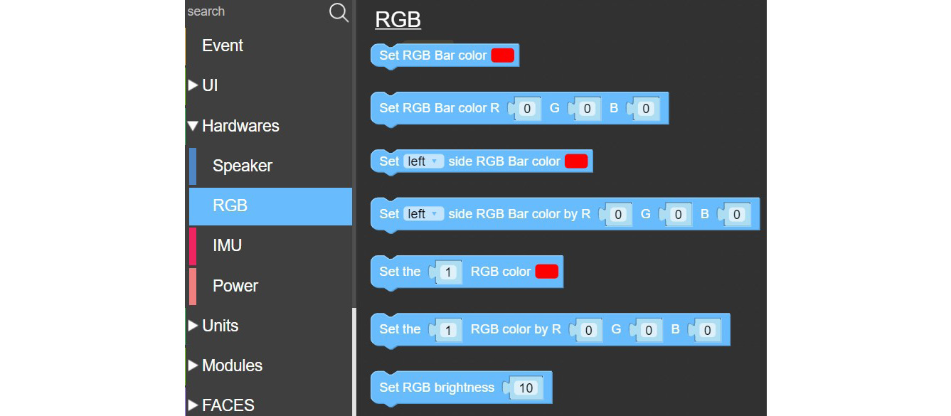
Figure 3.28 – RGB Blockly code block palette
Before building the RGB LED flasher, you will code a basic LED flashlight. To code this application on the M5Stack Core, you will use the Blockly code blocks shown in Figure 3.29:

Figure 3.29 – Basic LED flashlight code blocks
To adjust the red, green, and blue LEDs for a specific color, you can adjust the value using the slider control, as shown in Figure 3.30:

Figure 3.30 – Adjusting RGB colors using the slider control
You will adjust the green and blue values to 255. The final code block is shown in Figure 3.31:

Figure 3.31 – The final Blockly code blocks for the M5Stack Core LED flashlight
Note
Besides using the slider control, you can enter the values directly into the textbox.
When you click the Run button in the top-right panel, the LED bars will turn on. You will notice that the color display is white. Therefore, your LED flashlight will emit white light. The value for obtaining white for the RGB parameters is 255. Figure 3.32 shows the white light being emitted from an M5Stack Core’s LED bars:

Figure 3.32 – M5Stack Core LED bars emitting white light
You will now code the B button to turn off the LED bars. The Blockly code blocks that will accomplish the function of your M5Stack Core LED flashlight are shown next:

Figure 3.33 – Completed LED flashlight Blockly code blocks
Run the code and press the A button, and the LED bars will turn on. Now, press the B button, and the LED bars will turn off. Congratulations, you have created a flashlight using an M5Stack Core. The final step in this coding project is to make an RGB LED flasher. The next section will provide the Blockly code blocks to build the RGB LED flasher.
Interactive quiz 7
Using the LED flashlight Blockly code blocks shown in Figure 3.33, draw a block diagram for them.
Programming the M5Stack Core to operate the RGB LED as an LED flasher
In this final project, you will code the M5Stack Core to flash the RGB LED bars to run until the repeat value is reached. The A button starts the RGB LED bars’ flashing cycle. The repeat loop code block will run a set of code block instructions. When the repeat loop code block has completed the instructions for operating the RGB LED bars, the flashing effect will stop. To track the repeat loop code block instructions, a counter is included. The counter keeps track of every on-and-off flash cycle. The timing between flashing the RGB LED on and off is 1 second. Therefore, it takes 2 seconds to complete one flashing cycle. The complete LED flasher Blockly code blocks are shown in Figure 3.34.
Note
Counters are used in various applications requiring events to be sequenced properly.

Figure 3.34 – RGB LED flasher Blockly code
To build the counter, you will need to create a variable. You can create the counter variable by accessing its code block palette. Figure 3.35 shows the palette of Blockly code blocks available when the counter variable is created:

Figure 3.35 – The counter Blockly code palette
To display the counter on the M5Stack Core, a label placed on the TFT LCD is required. You configure the label using the techniques discussed previously in this chapter. The label will initially display Text on the M5Stack Core’s TFT LCD. As the code is being executed, the counter will display its numeric value on the TFT LCD as the flasher switching cycle is sequenced. Figure 3.36 illustrates the UI manager layout and properties for displaying the RGB LED flasher counter:
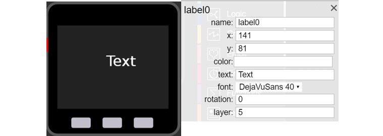
Figure 3.36 – The counter’s UI manager layout and properties
With the code built, execute the application by clicking the Run button in the top-right panel. You will see the word Text follow by the LED bars flashing in 1-second intervals. The counter increments will be visible on the M5Stack Core’s TFT LCD. Figure 3.37 illustrates the RGB LED flasher’s operation. You will notice, in reviewing the UIFlow Blockly code shown in Figure 3.34, that the counter increments every 2 seconds.

Figure 3.37 – The final RGB LED flasher operation
Interactive quiz 8
By changing the counter index value from 1 to 2 in the RGB LED flasher counter Blockly code shown in Figure 3.34, what starting count value will be displayed on the M5Stack Core TFT LCD?
Congratulations on completing the RGB LED flasher project! You have obtained knowledge of operating the internal M5Stack Core LED bar hardware using the UIFlow Blockly coding environment. You also have knowledge of using the counter and repeat Blockly code blocks to establish predefined flash rates for the LED bar hardware. In the final topic of this chapter, you will explore emojis and Blockly coding approaches to adding human-computer interaction to your M5Stack Core devices.
Coding an M5Stack Core interactive emoji
An emoji is a small icon that conveys the feelings of an individual in electronic mail or a document. With today’s computer graphics capabilities, emojis have evolved into interactive and animated forms of digital expression. You will learn how to create a basic emoji using the M5Stack Core. The UIFlow Blockly coding environment has a palette of Emoji blocks. With these coding blocks, you can create animated and interactive emojis. Figure 3.38 shows the Emoji code block palette:

Figure 3.38 – Emoji code block palette
The primary Emoji code block is the Set emoji map in instruction. The approach to using the Emoji code block is to select the pixel or square of interest by clicking it with your mouse. By selecting appropriate pixels, a two-dimensional (2D) image can be created. The Change backgroundimage code block allows a predefined background to be present with your emoji. There are six predefined backgrounds that you can select for your emoji. To begin the interactive emoji project, you will create a smiley face emoji. Figure 3.39 illustrates the pixels to select for the smiley face emoji:

Figure 3.39 – Smiley face emoji
With the appropriate code blocks placed on the UIFlow coding area, you will click the Run button to display the emoji on your M5Stack Core’s TFT LCD. You will see a smiley emoji, as shown in Figure 3.40. The background is the default setting of 0.

Figure 3.40 – M5Stack Core smiley emoji
You will create a sad emoji using the same approach that you used to make a smiley face. Here are the code blocks to create the sad emoji:

Figure 3.41 – M5Stack Core sad emoji code blocks
With the appropriate code blocks placed in the UIFlow coding area, you will click the Run button to display the emoji on your M5Stack Core’s TFT LCD. You will see a sad emoji, as shown in Figure 3.42. The background is the default setting of 0.
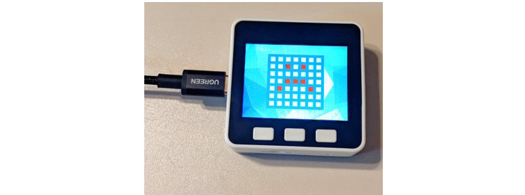
Figure 3.42 – M5Stack Core sad emoji
With two emoji blocks created, you will combine them to create a free-running animated emoji. You will use a Wait code block to provide a 1-second delay in displaying a smiley and sad emoji on the M5Stack Core TFT LCD. The code to accomplish this animation control function is shown in Figure 3.43:

Figure 3.43 – Emoji animated control code blocks
With the appropriate code blocks placed in the UIFlow coding area, you will click the Run button to display the animated emoji on your M5Stack Core’s TFT LCD. You will see the smiley and sad emojis toggling, and the default background setting of 0 will be displayed. To add an interactive control feature, the A, B, and C buttons will be used. The features for each of the buttons are as follows: the A button will toggle the smiley and sad emojis, the B button will select the smiley emoji, and the C button will display the sad emoji. Figure 3.44 shows the final interactive emoji Blockly code blocks:

Figure 3.44 – The final interactive emoji Blockly code blocks
With the appropriate code blocks placed in the UIFlow coding area, you will click the Run button to execute the interactive emoji application on your M5Stack Core. You will see the animated emoji running on the M5Stack Core’s TFT LCD when the A button is pressed. The smiley emoji will be displayed by pressing the B button. Pressing the C button will show the sad emoji. The background is the default setting of 0. Congratulations on completing the final project in the chapter!
Summary
Congratulations, you have completed the hands-on activities and interactive quizzes in this chapter! In the chapter, you learned about the circuit technologies used in the M5Stack Core. You learned how to draw block diagrams representing the M5Stack Core hardware architecture. You learned how to make a haptic controller using the M5Stack Core, a littleBits vibration motor module, and the hardware proto module. With the sound code blocks, you learned how to make a tone generator for a simulated warning alarm. You also explored the M5Stack Core’s LED bars. In the hands-on exploration, you were able to make an electronic flashlight and an RGB LED flasher. These projects were accomplished with an RGB code blocks palette. In addition, you used your coding knowledge to answer the interactive quizzes through hands-on investigation. Lastly, you explored emojis in this chapter. You created an interactive emoji using the emoji code blocks within the UIFlow coding area.
With this knowledge, you will be able to explore the M5Stack Core as a programmable controller to operate external electronic circuits in the next chapter. The M5Stack Core input and output hardware ports will allow external electronic circuits to be operated with the M5Stack Core. You will use your knowledge of the M5Stack Core’s subcircuits and hardware architecture to assist in wiring and controlling external electronic circuits.
Interactive quiz answers
- Interactive quiz 1:
- Interactive quiz 2: The vibration motor will initially be off.
- Interactive quiz 3: The voltage source from the B port will be approximately 3.3V.
- Interactive quiz 4: The digital toggle pin code block.
- Interactive quiz 5: Xc = 15.9 KΩ.
- Interactive quiz 6: Change the Wait code block value to 1 for 1 second.
- Interactive quiz 7:

- Interactive quiz 8: The counter start value will be 2.