
There is nothing more frustrating than receiving complicated advice as a solution to a problem. Because of this, I have always made it a point to focus on the fundamentals. In order to render graphics on the JavaFX scene, you will need basic shapes and colors. Expanding upon your knowledge of the JavaFX scene graph, which you visited toward the end of Chapter 1, you will learn in this chapter how to draw and manipulate 2D shapes on the JavaFX scene graph.
Even more fundamental than a shape object is JavaFX’s javafx.scene.Node class. The Node class is a fundamental base class for all JavaFX scene graph nodes. The Node class provides the ability to transform, translate, and apply effects to any node. Many examples in this chapter involve the javafx.scene.shape.Shape class, which is a descendant of the Node class. Therefore, the Shape class will inherit all of the Node class’ capabilities. In this chapter you will explore many derived classes that inherit from Shape. You will begin this chapter by examining JavaFX’s most basic shape, the Line node.
Rendering lines in JavaFX is conceptually similar to Euclidean geometry in that two (x, y) coordinate points connect to draw a segment into space. When drawn on the JavaFX scene graph, lines are rendered using the screen coordinate space (system). In geometry, a line is defined as a segment connected by two points in space, although it lacks a width (thickness) and color value. Does this mean that the line is invisible? In the computer world, physical devices plot pixels and shapes that occupy real surfaces. Monitors and printers are examples of such surfaces. Because of this method of production, modern graphics programming has adopted the standard screen coordinate system. In this system, lines that are drawn are visible and have attributes of width and color.
In a nutshell, the standard screen coordinate system places (0, 0) at the upper-left corner; this differs from the Cartesian coordinate system, where (0, 0) is placed at the center of the graphing area or the point at which the x and y axes converge. In both coordinate systems, the x coordinate has the same effect when moving a point along the x axis. However, when using the screen coordinate system to move along the y axis, the effect is opposite that of the Cartesian system. In other words, the y coordinate’s value increases when moving a point in a downward direction (top to bottom). Figure 2-1 illustrates shapes drawn using the screen coordinate system. Also note that using negative values will plot objects off the screen.
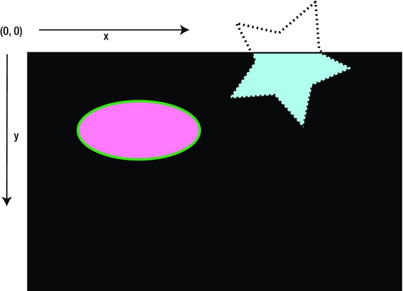
Figure 2-1. The screen coordinate system
As you learn more about JavaFX, you will discover many scene graph objects, such as lines, circles, and rectangles. These objects are derived classes of the Shape class. All shape objects can perform geometric operations between two shaped areas, such as subtract, intersect and union. By mastering the Shape API, you will begin to see endless possibilities. Now let’s discuss how to create lines.
To draw lines in JavaFX, you will use the javafx.scene.shape.Line class. When creating a Line instance you need to specify a start (x, y) coordinate and an end coordinate to draw a line. There are two ways to specify the start and end points when creating Line nodes. The first method is to use a constructor with the parameters startX, startY, endX, and endY. The data types of all the parameters are double values, which provide floating-point decimal precision. The following line has a start point (100, 10) and end point (10, 110) created using a constructor.
Line line = new Line(100, 10, 10, 110);
The second method to create a line node is to instantiate a Line class by using the empty default constructor and subsequently setting each attribute using associated setter methods. The following code snippet shows how to specify a line’s start and end points using setter methods.
Line line = new Line();
line.setStartX(100);
line.setStartY(10);
line.setEndX(10);
line.setEndY(110);
Line nodes drawn on the scene graph default to a stroke width of 1.0 (double) and a stroke color of black (Color.BLACK). According to the Javadoc, all shapes have a stroke color of null (no color) except Line, Polyline, and Path nodes.
Now that you know how to draw lines on the scene graph, you are probably wondering how to be more creative with lines. Creating different kinds of lines is simple; you basically set properties inherited from the parent class (javafx.scene.shape.Shape). Table 2-1 shows the properties you can set on a line (Shape). To retrieve or modify each property, you will use its appropriate getter and setter methods. The table lists each property name and its data type, with a description. Please refer to the Javadoc documentation for more details.
Table 2-1. The javafx.scene.shape.Shape Class Properties
Property |
Data Type |
Description |
|---|---|---|
fill |
javafx.scene.paint.Paint |
A color to fill inside a shape. |
smooth |
Boolean |
True turns on anti-aliasing, otherwise false. |
strokeDashOffset |
Double |
The offset (distance) into the dashed pattern. |
strokeLineCap |
javafx.scene.shape.StrokeLineCap |
The cap style on the end of a line or path. There are three styles: StrokeLineCap.BUTT, StrokeLineCap.ROUND, and StrokeLineCap.SQUARE. |
strokeLineJoin |
javafx.scene.shape.StrokeLineJoin |
Decoration when lines meet. There are three types: StrokeLineJoin.MITER, StrokeLineJoin.BEVEL, and StrokeLineJoin.ROUND. |
strokeMiterLimit |
Double |
The limit of a miter joint. Used along with the miter join decoration (StrokeLineJoin.MITER). |
stroke |
javafx.scene.paint.Paint |
A color for the shape’s line stroke. |
strokeType |
javafx.scene.shape.StrokeType |
Where to draw the stroke around the boundary of a Shape node. There are three types: StrokeType.CENTERED, StrokeType.INSIDE, and StrokeType.OUTSIDE. |
strokeWidth |
Double |
A stroke line’s width. |
To get a better idea of how you would use a shape’s properties based on Table 2-1, let’s look at an example. Figure 2-2 is the output of Listing 2-1, the DrawingLines.java source code, demonstrating the drawing of JavaFX lines. The JavaFX application in the listing draws three lines with various properties modified. Some common properties used in this example are stroke dash offset, stroke line cap, stroke width, and stroke color.
In Figure 2-2 you can see that the first line (top) is a thick red line with a dashed stroke pattern. The second line is a thick white line having rounded end caps (line cap). Last is an ordinary blue line having the same thickness as the others. You will also notice in Figure 2-2 underneath the blue line are a label and slider control; these allow the user to change the red (top) line’s stroke dash offset property dynamically. The label control displays the dash offset value as the slider control moves.
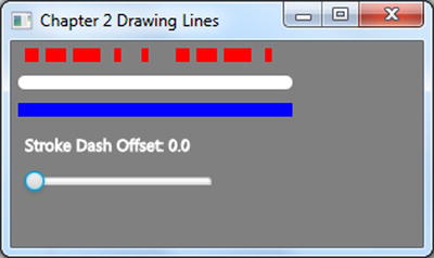
Figure 2-2. Drawing lines
Listing 2-1 shows the source code for DrawingLines.java.
Listing 2-1. DrawingLines.java
package jfx8ibe;

import javafx.application.Application;
import javafx.beans.value.ObservableValue;
import javafx.scene.Group;
import javafx.scene.Scene;
import javafx.scene.control.Slider;
import javafx.scene.paint.Color;
import javafx.scene.shape.Line;
import javafx.scene.shape.StrokeLineCap;
import javafx.scene.text.Text;
import javafx.stage.Stage;

/**
 * Drawing Lines
 * Listing 2-1 DrawingLines.java
 * @author carldea
 */
public class DrawingLinesextends Application {

   @Override
   public void start(Stage primaryStage) {
       primaryStage.setTitle("Chapter 2 Drawing Lines");

       Group root = new Group();
       Scene scene = new Scene(root, 300, 150, Color.GRAY);

       // Red line
       Line redLine = new Line(10, 10, 200, 10);

       // setting common properties
       redLine.setStroke(Color.RED);
       redLine.setStrokeWidth(10);
       redLine.setStrokeLineCap(StrokeLineCap.BUTT);

       // creating a dashed pattern
       redLine.getStrokeDashArray().addAll(10d, 5d, 15d, 5d, 20d);
       redLine.setStrokeDashOffset(0);

       root.getChildren().add(redLine);

       // White line
       Line whiteLine = new Line(10, 30, 200, 30);
       whiteLine.setStroke(Color.WHITE);
       whiteLine.setStrokeWidth(10);
       whiteLine.setStrokeLineCap(StrokeLineCap.ROUND);

       root.getChildren().add(whiteLine);

       // Blue line
       Line blueLine = new Line(10, 50, 200, 50);
       blueLine.setStroke(Color.BLUE);
       blueLine.setStrokeWidth(10);

       root.getChildren().add(blueLine);

       // slider min, max, and current value
       Slider slider = new Slider(0, 100, 0);
       slider.setLayoutX(10);
       slider.setLayoutY(95);

       // bind the stroke dash offset property
       redLine.strokeDashOffsetProperty()
              .bind(slider.valueProperty());
       root.getChildren()
           .add(slider);

       ;Text offsetText = new Text("Stroke Dash Offset: 0.0");
       offsetText.setX(10);
       offsetText.setY(80);
       offsetText.setStroke(Color.WHITE);

       // display stroke dash offset value
       slider.valueProperty()
             .addListener((ov, curVal, newVal) ->
                 offsetText.setText("Stroke Dash Offset: " + slider.getValue()));
       root.getChildren().add(offsetText);
               primaryStage.setScene(scene);
       primaryStage.show();
   }
   /**
    * @param args the command line arguments
    */
   public static void main(String[] args) {
       launch(args);
   }
}
DrawingLines.java begins by setting the title of the Stage window using the setTitle() method. Then it creates a root node (javafx.scene.Group) for the Scene object. All root nodes (those extending javafx.scene.Parent) have a method getChildren().add() to allow any JavaFX node to be added to the scene graph. By default the Scene object will be filled with a white background; however, because one of our lines is white, the code will set the scene to have a color of gray (Color.GRAY). This will allow some contrast in order to see the white line. Next is the code that creates the three lines (red, white and blue).
In the first line, the code sets the common properties of a Line node. The common properties are stroke color, stroke width, and stroke line cap. As noted earlier, lines do not have a shape internally, so a line’s fill color property is set to null (no color) and stroke color defaults to black. To set the stroke color you can use built-in JavaFX colors by using the javafx.scene.paint.Color class. For instance, for the color red you will use Color.RED. There are many ways to specify color, such as using RGB, HSB, or Web hex values. All three methods also have the ability to specify alpha value (transparency). Later, you will see additional methods for coloring shapes. Please refer to the Javadoc to learn more about color (javafx.scene.paint.Color). After setting the stroke’s outline color you can set the line’s stroke width (thickness) by using the setStrokeWidth() method. Shapes also have a stroke line cap property. This property specifies the style of the ends of the line. For instance, specifying the stroke line cap as butt (StrokeLineCap.BUTT) will make a flat square end, while a round (StrokeLineCap.ROUND) style will appear with a rounded end. The following code snippet sets a line node’s common shape properties:
// setting common properties
redLine.setStroke(Color.RED);
redLine.setStrokeWidth(10);
redLine.setStrokeLineCap(StrokeLineCap.BUTT);
After setting the common properties on the red Line node, the example code creates a dashed pattern. To form a dashed pattern you would simply add double values to the getStrokeDashArray().add() method. Each value represents the number of pixels for a dash segment. To set the dash segment array, the first value (10d) is a visible dash segment 10 pixels wide. Next is a five-pixel empty segment (not visible). Following that is a visible dash segment 15 pixels wide, and so on. Because the array has an odd number of values, you can see that as the pattern repeats itself, the first value (10d) becomes a 10-pixel empty segment (not visible). Following is the code to create a dashed pattern for a Line node:
// creating a dashed pattern
redLine.getStrokeDashArray().addAll(10d, 5d, 15d, 5d, 20d);
redLine.setStrokeDashOffset(0);
By default the dash offset property value is zero. To see what happens when the offset property changes, the user can drag the slider thumb to the right to increase the offset. The stroke dash offset is the distance into the current pattern to begin the line drawing.
Because the other two lines are pretty much the same in the way they modify common properties, I will not explain them any further. I trust you now understand the fundamentals of creating lines. One last thing to mention about this example is the Slider control and the way it is wired up using binding. We will discuss binding further in Chapter 3.
Notice in Listing 2-1 also that after the three lines just discussed, the slider control has handler code that updates a Text node dynamically to display the dash offset value. Also notice the invocation to the addListener() method, containing concise code added as a change listener. This may look odd to you; however, it reflects a new Java 8 feature called lambda expressions, which you will learn more about in Chapter 3. The following code snippet creates a change listener using lambdas instead of an anonymous inner class (ChangeListener).
// display stroke dash offset value
slider.valueProperty()
      .addListener( (ov, oldVal, newVal) ->
            offsetText.setText("Stroke Dash Offset: " + slider.getValue()));
Learning about how to draw lines will help you apply the same knowledge to any Shape node in JavaFX. These important concepts will allow you to create any kind of shape styled the way you see fit. Speaking of shapes, that’s what we’ll discuss next.
If you are familiar with drawing programs that allows a user to draw shapes on the canvas, you’ll notice a lot of similarities when using the JavaFX’s Shape API. The JavaFX Shape API allows you to create many common shapes such as lines, rectangles, and circles. Some of the more complex shapes are Arc, CubicCurve, Ellipse, and QuadCurve. JavaFX also lets you create custom shapes for situations where the predefined stock shapes don’t fit the bill. In this section you will be exploring basic shapes, complex shapes, and custom shapes. I will not demonstrate all of the shapes available to JavaFX, because of space limitations. To see all the available shapes, refer to the Javadoc documentation for details.
As stated earlier, JavaFX has common shapes such as lines, rectangles and circles. In the section “Drawing Lines,” you learned the basic method of changing any shape’s stroke color, stroke width, and many other attributes. Knowing these skills will be useful throughout this chapter. Let’s begin by getting familiar with the rectangle shape.
Drawing rectangles on the scene graph is quite easy. Just as you learned in a geometry classroom, you specify a width, height, and an (x, y) location (upper-left corner) to position the rectangle on the scene graph. To draw a rectangle in JavaFX you use the javafx.scene.shape.Rectangle class. In addition to common attributes, the Rectangle class also implements an arc width and arc height. This feature will draw rounded corners on a rectangle. Figure 2-3 shows a rounded rectangle, which has both an arc width and an arc height.

Figure 2-3. A rounded rectangle’s arc width and arc height
Following is a code snippet that draws a rectangle positioned at (50, 50) with a width of 100, a height of 130, an arc width of 10, and an arc height of 40.
Rectangle roundRect = new Rectangle();
roundRect.setX(50);
roundRect.setY(50);
roundRect.setWidth(100);
roundRect.setHeight(130);
roundRect.setArcWidth(10);
roundRect.setArcHeight(40);
Having the basic knowledge of simple shapes such as lines and rectangles you will inevitably come across other simple shapes having equivalent properties that we can manipulate in the same way. Armed with this knowledge of simple shapes let’s look at creating more complex shapes.
Drawing Complex Shapes
Learning about simple shapes is great, but to create more complex shapes you need to see what other built-in shapes that the JavaFX API has to offer. Exploring the Java documentation (javafx.scene.shape.*), you will discover many derived shape classes to choose from. The following are all the currently supported shapes:
- Arc
- Circle
- CubicCurve
- Ellipse
- Line
- Path
- Polygon
- Polyline
- QuadCurve
- Rectangle
- SVGPath
- Text (which is considered to be a type of shape)
To demonstrate the drawing of complex shapes, the next code example draws four fun cartoon-like shapes. Normally cartoon drawings have a thick stroke width, similar to a penciled-in outline. The first shape in the example is a sine wave; the second an ice cream cone, the third a smile, and the last a donut. Before studying the code you may want to see the shapes drawn onto the scene, so you can visualize each shape as you look at the code listing. Figure 2-4 is the output of Listing 2-2, depicting four complex shapes.

Figure 2-4. Drawing complex shapes
The DrawingShape.java code shown in Listing 2-2 demonstrates the drawing of the shapes you see in Figure 2-4. The first complex shape involves a cubic curve (CubicCurve) that is drawn in the shape of a sine wave. The next shape is an ice cream cone; it uses the Path class, which contains path elements (javafx.scene.shape.PathElement). The third shape is a Quadratic Bézier curve (QuadCurve) forming a smile. Our final shape is a delectable donut; to create this donut shape you will create two (Ellipse) shapes (one smaller and one larger) and subtract one. For brevity, Listing 2-2 shows just the start() method, containing the main JavaFX elements. To get the full code listing, download the example code from the book’s web site.
Listing 2-2. DrawingShape.java
   @Override
public void start(Stage primaryStage) {
    primaryStage.setTitle("Chapter 2 Drawing Shapes");
    Group root = new Group();
    Scene scene = new Scene(root, 306, 550, Color.WHITE);

    // Sine wave
    CubicCurve cubicCurve = new CubicCurve(
            50,  // start x point
            75,  // start y point
            80,  // control x1 point
            -25, // control y1 point
            110, // control x2 point
            175, // control y2 point
            140, // end x point
            75); // end y point
    cubicCurve.setStrokeType(StrokeType.CENTERED);
    cubicCurve.setStroke(Color.BLACK);
    cubicCurve.setStrokeWidth(3);
    cubicCurve.setFill(Color.WHITE);

    root.getChildren().add(cubicCurve);

    // Ice cream cone
    Path path = new Path();
    path.setStrokeWidth(3);

    // create top part beginning on the left
    MoveTo moveTo = new MoveTo();
    moveTo.setX(50);
    moveTo.setY(150);

    // curve ice cream (dome)
    QuadCurveTo quadCurveTo = new QuadCurveTo();
    quadCurveTo.setX(150);
    quadCurveTo.setY(150);
    quadCurveTo.setControlX(100);
    quadCurveTo.setControlY(50);

    // cone rim
    LineTo lineTo1 = new LineTo();
    lineTo1.setX(50);
    lineTo1.setY(150);

    // left side of cone
    LineTo lineTo2 = new LineTo();
    lineTo2.setX(100);
    lineTo2.setY(275);

    // right side of cone
    LineTo lineTo3 = new LineTo();
    lineTo3.setX(150);
    lineTo3.setY(150);

    path.getElements().addAll(moveTo, quadCurveTo, lineTo1, lineTo2 , lineTo3);

    path.setTranslateY(30);

    root.getChildren().add(path);

    // A smile
    QuadCurve quad = new QuadCurve(
            50, // start x point
            50, // start y point
            125,// control x point
            150,// control y point
            150,// end x point
            50);// end y point
    quad.setTranslateY(path.getBoundsInParent().getMaxY());
    quad.setStrokeWidth(3);
    quad.setStroke(Color.BLACK);
    quad.setFill(Color.WHITE);

    root.getChildren().add(quad);

    // outer donut
    Ellipse bigCircle = new Ellipse(
            100,   // center x
            100,   // center y
            50,    // radius x
            75/2); // radius y
    bigCircle.setStrokeWidth(3);
    bigCircle.setStroke(Color.BLACK);
    bigCircle.setFill(Color.WHITE);

    // donut hole
    Ellipse smallCircle = new Ellipse(
            100,   // center x
            100,   // center y
            35/2,  // radius x
            25/2); // radius y

    // make a donut
    Shape donut = Path.subtract(bigCircle, smallCircle);
    donut.setStrokeWidth(1.8);
    donut.setStroke(Color.BLACK);

    // orange glaze
    donut.setFill(Color.rgb(255, 200, 0));

    // add drop shadow
    DropShadow dropShadow = new DropShadow(
        5,    // radius
        2.0f, // offset X
        2.0f, // offset Y
        Color.rgb(50, 50, 50, .588));

    donut.setEffect(dropShadow);

    // move slightly down
    donut.setTranslateY(quad.getBoundsInParent().getMinY() + 30);

    root.getChildren().add(donut);

    primaryStage.setScene(scene);
    primaryStage.show();
}
Four shapes are drawn in Figure 2-4. Each shape will be detailed further in the following sections, which describe the code and the reasoning behind the creation of each of the four shapes.
In Listing 2-2 the first shape, drawn as a sine wave, is really a javafx.scene.shape.CubicCurve class. To create a cubic curve, you simply look for the appropriate constructor to be instantiated. A cubic curve’s main parameters to set are startX, startY, controlX1 (control point1 X), controlY1 (control point1 Y), controlX2 (control point2 X), and controlY2 (control point2 Y), endX, endY. Figure 2-5 shows a cubic curve with control points influencing the curve.

Figure 2-5. Cubic curve
The startX, startY, endX, and endY parameters are the starting and ending points of a curved line, and controlX1, controlY1, controlX2, and controlY2 are control points. The control point (controlX1, controlY1) is a point in screen space that will influence the line segment between the start point (startX, startY) and the midpoint of the line. The point (controlX2, controlY2) is another control point that will influence the line segment between the midpoint of the line and its end point (endX, endY). A control point is a point that pulls the curve toward the direction of itself. A definition of a control point is a line perpendicular to a tangent line on the curve. In our example, we simply have a control point 1 above the line to pull the curve upward to form a hill and control point 2 below the line to pull the curve downward to form a valley.
Note All older JavaFX 2.x Builder classes are deprecated in JavaFX 8. Be advised that the previous edition of this book used Builder classes. Shape classes using deprecated builder classes should be converted in favor of constructors and setter methods when specifying properties.
At this point I want to mention that beginning with JavaFX 8, Oracle’s JavaFX team has decided to deprecate the many Builder classes in JavaFX. The decision to deprecate builder classes was mainly due to two bugs found in Java 6 & 7 that were fixed in Java 8. The bug fixes would later cause binary compatibility issues that would break the builder classes. To get the full story please see Chapter 13 in the section under JavaFX 8’s Features which references links to the discussions about the issue of builder classes. Knowing this will allow you to recognize older JavaFX 2.x code so that refactoring should be painless. The first edition of this book used Builder classes quite frequently, and they are an elegant way to create JavaFX objects. Although the Builder classes are deprecated, it doesn’t prevent us from creating APIs with the builder pattern in mind. To create objects without an associated builder class, just find the appropriate constructor to be instantiated or use setter methods to set the object’s properties.
The ice cream cone shape is created using the javafx.scene.shape.Path class. Each path element is created and added to the Path object. Also, each element is not considered a graph node (javafx.scene.Node). This means that path elements do not extend from the javafx.scene.shape.Shape class and they cannot be child nodes in a scene graph to be displayed. Figure 2-6 shows an ice cream cone shape.

Figure 2-6. The ice cream cone is drawn using JavaFX’s Path node
Path elements actually extend from the javafx.scene.shape.PathElement class, which is used only in the context of a Path object. So you won’t be able to instantiate a LineTo class to be put in the scene graph. Just remember that the classes with To as a suffix are path elements, not Shape nodes.
For example, the MoveTo and LineTo object instances are Path elements added to a Path object, not shapes that can be added to the scene. Following are Path elements added to a Path object to draw an ice cream cone:
// Ice cream
Path path = new Path();

MoveTo moveTo = new MoveTo();
moveTo.setX(50);
moveTo.setY(150);

...// Additional Path Elements created.
LineTo lineTo1 = new LineTo();
lineTo1.setX(50);
lineTo1.setY(150);

...// Additional Path Elements created.

path.getElements().addAll(moveTo, quadCurveTo, lineTo1, lineTo2 , lineTo3);
The Smile
To render the smile shape, the code uses the javafx.scene.shape.QuadCurve class. This is similar to the cubic curve example described earlier in the first shape. Instead of two control points you only have one control point. Again, a control point influences a line by pulling the midpoint toward it. Shown in Figure 2-7 is a QuadCurve shape with a control point below its starting and ending points to form a smile.
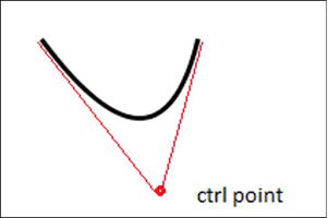
Figure 2-7. Quadratic curve
The following code draws a quadratic curve with a stroke thickness of three pixels filled with the color white:
// A smile
QuadCurve quad = new QuadCurve(
        50, // start x point
        50, // start y point
        125,// control x point
        150,// control y point
        150,// end x point
        50);// end y point

quad.setStrokeWidth(3);
quad.setStroke(Color.BLACK);
quad.setFill(Color.WHITE);
Last is our tasty donut shape with an interesting drop shadow effect shown in Figure 2-8. This custom shape was created using geometric operations such as subtract, union, intersection, and so on. With any two shapes you can perform geometric operations to form an entirely new shape object. All of the operations can be found in the javafx.scene.shape.Path class.
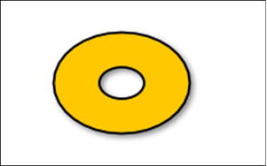
Figure 2-8. A donut shape created by using shape subtraction
To create the donut shape, you begin by creating two circular ellipse (javafx.scene.shape.Ellipse) instances. Subtracting the smaller ellipse (donut hole) from the larger ellipse area creates a newly derived Shape object, which is returned using the static Path.subtract() method. The following code snippet creates the donut shape using the Path.subtract() method:
// outer donut
Ellipse bigCircle = ...//Outer shape area

// donut hole
Ellipse smallCircle = ...// Inner shape area

// make a donut
Shape donut = Path.subtract(bigCircle, smallCircle);
Next is applying a drop shadow effect to the donut shape. A common technique is to draw the shape filled black while the original shape is laid on top slightly offset to appear as a shadow. However, in JavaFX the code will be drawing the donut shape once and use the setEffect() method to apply a DropShadow object instance. To cast the shadow offset, call the setOffsetX() and setOffsetY() methods. Typically if the light source is from the upper left, the shadow is shown from the lower right of the shape.
One last thing to point out is that all shapes in the example are initially drawn to be positioned underneath one another. Looking back at Listing 2-2, you’ll notice that as each shape was created, its translateY property was set to reposition or shift each shape from its original position. For example, if a shape’s upper-left bounding box point is created at (100, 100) and you want it to be moved to (101, 101), the translateX and translateY properties would be set to 1.
As each shape is rendered beneath another in this example, you may invoke the getBoundsInParent() method to return the information about the bounding region of a node, such as its width and height. The getBoundsInParent() calculation for the height and width includes the node’s actual dimensions (width and height) plus any effects, translations, and transformations. For example, a shape that has a drop shadow effect increases its width by including the shadow.
Figure 2-9 is a dashed red rectangle surrounding a Rectangle node inside a parent node better known as the bounding rectangle in parent (Bounds in Parent). You will notice that the width and height calculations include transforms, translates, and effects applied to the shape. In the figure, the transform operation is a rotation and the effect is a drop shadow.

Figure 2-9. Bounding rectangle in parent
I’ve mentioned that various drawing programs have their own tools to draw shapes. Drawing programs also provide the ability to paint shapes, using a color palette. Typically, paint programs have a paint bucket tool to fill areas on the canvas. Often, photo editing software packages have the ability to fill using a gradient color or change the lighting of colors. In JavaFX you can also apply colors (Paint) to objects using similar techniques. In this section you will see an example of a JavaFX application that will showcase three shapes filled with colors (Paint).
An Example of Color
To demonstrate common color fills, Figure 2-10 illustrates an application that displays three shapes, with different color fills. It depicts the following three shapes: ellipse, rectangle, and rounded rectangle. Each shape has a gradient fill. The first shape, the ellipse, is filled with a red radial gradient. The second is a rectangle filled with a yellow linear gradient. Finally, the rounded rectangle has a green cycle reflect gradient fill. You’ll also notice a thick black line behind the yellow rectangle to illustrate the alpha level (transparency) of colors.

Figure 2-10. Colored shapes
Note The example to follow touches on basic techniques for creating solid colors, gradient colors, and translucent colors. There are also advanced strategies, such as the ImagePattern API and Blend API. You can read about those, if you are interested, in the API documentation viewable through Javadoc.
In JavaFX, all shapes can be filled with simple colors and gradient colors. As a reminder, according to the Javadoc all shape nodes are filled with the color black by default except for Line, Polyline, and Path class (descendents of java.scene.shape.Shape). Listing 2-3 uses the following main classes that will be used to fill the shape nodes shown in Figure 2-10:
- javafx.scene.paint.Color
- javafx.scene.paint.Stop
- javafx.scene.paint.RadialGradient
- javafx.scene.paint.LinearGradient
Note In figure 2-10, the blackLine, rectangle, and roundRectangle shapes are all positioned by the setTranslateY() method relative to the ellipse shape and to one another.
Listing 2-3. PaintingColors.java
@Override
public void start(Stage primaryStage) {
    primaryStage.setTitle("Chapter 2 Painting Colors");
    Group root = new Group();
    Scene scene = new Scene(root, 350, 300, Color.WHITE);

    // Red ellipse with radial gradient color
    Ellipse ellipse = new Ellipse(100, // center X
            50 + 70/2, // center Y
            50,        // radius X
            70/2);     // radius Y
    RadialGradient gradient1 = new RadialGradient(
            0,    // focusAngle
            .1,   // focusDistance
            80,   // centerX
            45,   // centerY
            120,  // radius
            false, // proportional
            CycleMethod.NO_CYCLE, // cycleMethod
            new Stop(0, Color.RED), // stops
              new Stop(1, Color.BLACK)
    );

    ellipse.setFill(gradient1);
    root.getChildren().add(ellipse);
    double ellipseHeight = ellipse.getBoundsInParent()
                                  .getHeight();

    // thick black line behind second shape
    Line blackLine = new Line();
    blackLine.setStartX(170);
    blackLine.setStartY(30);
    blackLine.setEndX(20);
    blackLine.setEndY(140);
    blackLine.setFill(Color.BLACK);
    blackLine.setStrokeWidth(10.0f);
    blackLine.setTranslateY(ellipseHeight + 10);

    root.getChildren().add(blackLine);

    // A rectangle filled with a linear gradient with a translucent color.
    Rectangle rectangle = new Rectangle();
    rectangle.setX(50);
    rectangle.setY(50);
    rectangle.setWidth(100);
    rectangle.setHeight(70);
    rectangle.setTranslateY(ellipseHeight + 10);

    LinearGradient linearGrad = new LinearGradient(
            0,   // start X
            0,   // start Y
            0,   // end X
            1, // end Y
            true, // proportional
            CycleMethod.NO_CYCLE, // cycle colors
            // stops
            new Stop(0.1f, Color.rgb(255, 200, 0, .784)),
            new Stop(1.0f, Color.rgb(0, 0, 0, .784)));

    rectangle.setFill(linearGrad);
    root.getChildren().add(rectangle);

    // A rectangle filled with a linear gradient with a reflective cycle.
    Rectangle roundRect = new Rectangle();
    roundRect.setX(50);
    roundRect.setY(50);
    roundRect.setWidth(100);
    roundRect.setHeight(70);
    roundRect.setArcWidth(20);
    roundRect.setArcHeight(20);
    roundRect.setTranslateY(ellipseHeight + 10 +
                rectangle.getHeight() + 10);

    LinearGradient cycleGrad = new LinearGradient(
            50, // start X
            50, // start Y
            70, // end X
            70, // end Y
            false, // proportional
            CycleMethod.REFLECT,  // cycleMethod
            new Stop(0f, Color.rgb(0, 255, 0, .784)),
            new Stop(1.0f, Color.rgb(0, 0, 0, .784))
    );
    roundRect.setFill(cycleGrad);
    root.getChildren().add(roundRect);

    primaryStage.setScene(scene);
    primaryStage.show();
}
When specifying color values, the PaintingColors.java code uses the colors in the default RGB color space. To create a color, the code uses the Color.rgb() method. This method takes three integer values, representing red, green, and blue components. Another overloaded method takes three integer values and a fourth parameter with a data type of double. This fourth parameter is the alpha channel, which sets the opacity of the color. This value is between zero (0) and one (1).
Note Keep in mind that there are other ways to create color, such as by specifying hue, saturation, and brightness (HSB). To create a color using HSB, you would invoke the Color.hsb() method. Another way to specify color values that is common to web development in HTML and CSS is the use of RGB hexadecimal values. Developers who are familiar with this convention can use the Color.web() method.
After drawing the ellipse shape, the code invokes the setFill() method using a radial gradient to give the appearance of a 3D spherical object. Next, it creates a rectangle filled with a yellow semitransparent linear gradient. Added behind the yellow rectangle is a thick black line to demonstrate the semitransparent color. Finally, the code implements a rounded rectangle filled with a green-and-black reflective linear gradient resembling 3D tubes in a diagonal direction. Each shape and its associated color fill will be discussed in more detail in the following sections.
Creating a gradient color in JavaFX involves five things:
- A starting point to begin the first stop color.
- The end point, representing the end stop color.
- The proportional property to specify whether to use standard screen coordinates or unit square coordinates.
- The Cycle method to specify one of the three enums: NO_CYCLE, REFLECT, or REPEAT.
- An array of stop (Stop) colors. Each stop containing a color will begin by painting the first stop color, then interpolating to the second stop color, and so on.
When dealing with either linear or radial gradient color, pay special attention to the proportional attribute. By setting this attribute to false, you can draw a line (the gradient axis) having a beginning point (start X, start Y) and an end point (end X, end Y) based on standard screen (x, y) coordinates.
However, if the proportional attribute is set to a value of true, the gradient axis line beginning and ending points will be represented as unit square coordinates. This means that x, y coordinates for begin and end points must be between 0.0 and 1.0 (double). This strategy is more compact and easier to define than screen coordinates on the scene graph.
The amazing thing about colors with gradients is that they can often make shapes appear three-dimensional. Gradient paint allows you to interpolate between two or more colors, which gives depth to the shape. JavaFX provides two types of gradients: a radial (RadialGradient) and a linear (LinearGradient) gradient. For our ellipse shape you will be using a radial gradient (RadialGradient).
Table 2-2 presents the JavaFX 8 Javadoc definitions found for the RadialGradient class. You can find this documentation at the following URL:
http://docs.oracle.com/javase/8/javafx/api/javafx/scene/paint/RadialGradient.html
Table 2-2. RadialGradient Properties
Property |
Data Type |
Description |
|---|---|---|
focusAngle |
Double |
Angle in degrees from the center of the gradient to the focus point to which the first color is mapped. |
focusDistance |
Double |
Distance from the center of the gradient to the focus point to which the first color is mapped. |
centerX |
Double |
X coordinate of the center point of the gradient’s circle. |
centerY |
Double |
Y coordinate of the center point of the gradient’s circle. |
radius |
Double |
Radius of the circle defining the extents of the color gradient. |
proportional |
boolean |
Coordinates and sizes are proportional to the shape this gradient fills. |
cycleMethod |
CycleMethod |
Cycle method applied to the gradient. |
Stops |
List<Stop> |
Gradient’s color specification. |
In our example the focus angle is set to zero, the distance is set to .1, center X and Y are set to (80, 45), the radius is set to 120 pixels, proportional is set to false, the cycle method is set to the no cycle (CycleMethod.NO_CYCLE), and two color stop values set to red (Color.RED) and black (Color.BLACK). These settings give a radial gradient to our ellipse by starting with the color red with a center position of (80, 45) (upper left of the ellipse) that interpolates to the color black with a distance of 120 pixels (radius).
Semitransparent Gradients
Next, you will see how to create the rectangle, which has a yellow semitransparent linear gradient. For our yellow rectangle you will use a linear gradient (LinearGradient) paint.
Table 2-3 presents the JavaFX 8 Javadoc definitions found for the LinearGradient class. You can find the definitions also at the following URL:
http://docs.oracle.com/javase/8/javafx/api/javafx/scene/paint/LinearGradient.html
Table 2-3. LinearGradient Properties
Property |
Data Type |
Description |
|---|---|---|
startX |
Double |
X coordinate of the gradient axis start point. |
startY |
Double |
Y coordinate of the gradient axis start point. |
endX |
Double |
X coordinate of the gradient axis end point. |
endY |
Double |
Y coordinate of the gradient axis end point. |
proportional |
Boolean |
Whether the coordinates are proportional to the shape which this gradient fills. When set to true use unit square coordinates, otherwise use scene/screen coordinate system. |
cycleMethod |
CycleMethod |
Cycle method applied to the gradient. |
stops |
List<Stop> |
Gradient’s color specification. |
To create a linear gradient paint, you specify startX, startY, endX, and endY for the start and end points. The start and end point coordinates denote where the gradient pattern begins and stops.
To create the second shape in Figure 2-10, the yellow rectangle, you set the start X and Y to (0.0, 0.0), end X and Y to (0.0, 1.0), proportional to true, the cycle method to no cycle (CycleMethod.NO_CYCLE), and two color stop values to yellow (Color.YELLOW) and black (Color.BLACK) with an alpha transparency of .784.These settings give a linear gradient to our rectangle from top to bottom with a starting point of (0.0, 0.0) (the top left of a unit square) that interpolates to the color black to an end point of (0.0, 1.0) (the bottom left of a unit square).
Finally, at the bottom of Figure 2-10 you’ll notice a rounded rectangle with a repeating pattern of a gradient using green and black in a diagonal direction. This is a simple linear gradient paint that is the same as the linear gradient paint (LinearGradient) except that the start X, Y and end X, Y values are set in a diagonal position, and the cycle method is set to reflect (CycleMethod.REFLECT). When specifying the cycle method to reflect (CycleMethod.REFLECT), the gradient pattern will repeat or cycle between the stop colors. The following code snippet implements the rounded rectangle having a cycle method of reflect (CycleMethod.REFLECT):
LinearGradient cycleGrad = new LinearGradient(
        50, // start X
        50, // start Y
        70, // end X
        70, // end Y
        false, // proportional
        CycleMethod.REFLECT,  // cycleMethod
        new Stop(0f, Color.rgb(0, 255, 0, .784)),
        new Stop(1.0f, Color.rgb(0, 0, 0, .784))
);
Another basic JavaFX node is the Text node. Text nodes allow you to display a string of characters onto the scene graph. To create Text nodes on the JavaFX scene graph you will use the javafx.scene.text.Text class. Because all JavaFX scene nodes extend from javafx.scene.Node they will inherit many capabilities such as the ability to be scaled, translated, or rotated.
Based on the Java inheritance hierarchy, the Text node’s direct parent is a javafx.scene.shape.Shape class which provides even more capabilities than the Node class. Because a Text node is both a Node and a Shape object it is able to perform geometric operation between two shape areas such as subtract, intersect, or union. You can also clip viewport areas with a shape similar to stenciled letters.
To demonstrate drawing text, in this section you will look at a basic example of how to draw text nodes on the scene graph. This example will touch on the following three capabilities:
- Positioning Text nodes using (x, y) coordinates
- Setting a Text node’s stroke color
- Rotating a Text node about its pivot point
To make things a little interesting, we will create 100 Text nodes and produce random values for the three capabilities just mentioned. Figure 2-11shows our drawing text example in action.
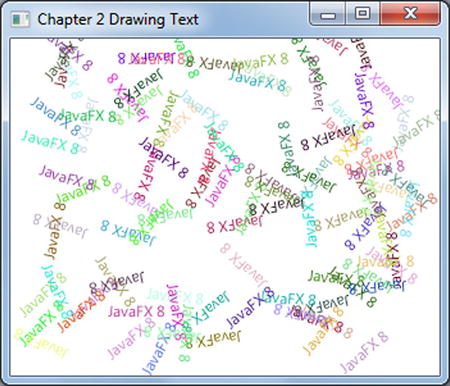
Figure 2-11. Drawing text
The DrawingText.java code shown in Listing 2-4 creates 100 Text nodes with randomly generated values for the following attributes:
- x, y coordinates
- RGB fill color
- Angle of rotation (degrees).
The code first creates a loop to generate random (x, y) coordinates to position Text nodes. In the loop, it creates random RGB color components between 0 and 255 to be applied to the Text nodes. Setting all components to zero produces black. Setting all three RGB values to 255 produces the color white.
Listing 2-4. DrawingText.java
@Override
public void start(Stage primaryStage) {
    primaryStage.setTitle("Chapter 2 Drawing Text");
    Group root = new Group();
    Scene scene = new Scene(root, 300, 250, Color.WHITE);
    Random rand = new Random(System.currentTimeMillis());
    for (int i = 0; i < 100; i++) {
        int x = rand.nextInt((int) scene.getWidth());
        int y = rand.nextInt((int) scene.getHeight());
        int red = rand.nextInt(255);
        int green = rand.nextInt(255);
        int blue = rand.nextInt(255);

        Text text = new Text(x, y, "JavaFX 8");

        int rot = rand.nextInt(360);
        text.setFill(Color.rgb(red, green, blue, .99));
        text.setRotate(rot);
        root.getChildren().add(text);
    }

    primaryStage.setScene(scene);
    primaryStage.show();
}
The rotation angle (in degrees) is a randomly generated value from 0–360 degrees, which causes the baseline of the text to be tilted. According to the API documentation the setRotate() method will rotate about the pivot point, which is the center of the untransformed layout bounds (layoutBounds) property. Basically, the pivot point is the center of a node that has no transforms (scaling, translating, shearing, rotating, and so on) applied.
Note If you need to use a combination of transforms, such as rotate, scale, and translate, take a look at the getTransforms().add(...) method. For more details on the difference between bounds in local, bounds in parent, and layout bounds, please see the Javadoc documentation.
The following code is used in DrawingText.java to create random values for a Text node’s x and y position (baseline), color, and rotation:
int x = rand.nextInt((int) scene.getWidth());
int y = rand.nextInt((int) scene.getHeight());
int red = rand.nextInt(255);
int green = rand.nextInt(255);
int blue = rand.nextInt(255);
int rot = rand.nextInt(360);
Once the random values are generated, they are applied to the Text nodes, which will be drawn onto the scene graph. Each Text node maintains a text origin property that contains the starting point of its baseline. In Latin-based alphabets, the baseline is an imaginary line underneath letters, similar to books on a bookshelf. However, some letters, such as the lowercase j, extend below the baseline. When specifying the x and y coordinate of the Text node you will be positioning the start of the baseline. In Figure 2-12, the x and y coordinate is located left of the lowercase j on the baseline in the text node “javafx 8.”
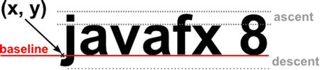
Figure 2-12. Text node’s baseline (x, y) coordinate position
The following code snippet applies (x, y) coordinates, color (RGB) with an opacity .99 and a rotation (angle in degrees) to the Text node:
Text text = new Text(x, y, "JavaFX 8");
text.setFill(Color.rgb(red, green, blue, .99));
text.setRotate(rot);

root.getChildren().add(text);
You should be starting to see the power of the scene graph API in its ease of use, especially when working with Text nodes. Here you were able to position, colorize, and rotate text. To spruce things up a bit more, you will next see how to change a text’s font and apply effects.
JavaFX’s Font API enables you to change font styles and font sizes in the same way as word processing applications. To demonstrate it, I created a JavaFX application that displays four text nodes with the string value of “JavaFX 8 Intro by Example,” each having a different font style. In addition to the font styles I also added effects such as a drop shadow (DropShadow) and reflection (Reflection).
Figure 2-13 shows the example’s output, and Listing 2-5 shows the ChangingTextFonts.java source code.
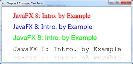
Figure 2-13. Changing text fonts
Listing 2-5. ChangingTextFonts.java
@Override
public void start(Stage primaryStage) {
    primaryStage.setTitle("Chapter 2 Changing Text Fonts");

    System.out.println("Font families: ");
    Font.getFamilies()
        .stream()
        .forEach( i -> System.out.println(i));
    System.out.println("Font names: ");
    Font.getFontNames()
        .stream()
        .forEach( i -> System.out.println(i));

    Group root = new Group();
    Scene scene = new Scene(root, 580, 250, Color.WHITE);

    // Serif with drop shadow
    Text text2 = new Text(50, 50, "JavaFX 8: Intro. by Example");
    Font serif = Font.font("Serif", 30);
    text2.setFont(serif);
    text2.setFill(Color.RED);
    DropShadow dropShadow = new DropShadow();
    dropShadow.setOffsetX(2.0f);
    dropShadow.setOffsetY(2.0f);
    dropShadow.setColor(Color.rgb(50, 50, 50, .588));
    text2.setEffect(dropShadow);
    root.getChildren().add(text2);

    // SanSerif
    Text text3 = new Text(50, 100, "JavaFX 8: Intro. by Example");
    Font sanSerif = Font.font("SanSerif", 30);
    text3.setFont(sanSerif);
    text3.setFill(Color.BLUE);
    root.getChildren().add(text3);

    // Dialog
    Text text4 = new Text(50, 150, "JavaFX 8: Intro. by Example");
    Font dialogFont = Font.font("Dialog", 30);
    text4.setFont(dialogFont);
    text4.setFill(Color.rgb(0, 255, 0));
    root.getChildren().add(text4);

    // Monospaced
    Text text5 = new Text(50, 200, "JavaFX 8: Intro. by Example");
    Font monoFont = Font.font("Monospaced", 30);
    text5.setFont(monoFont);
    text5.setFill(Color.BLACK);
    root.getChildren().add(text5);

    // Reflection
    Reflection refl = new Reflection();
    refl.setFraction(0.8f);
    refl.setTopOffset(5);
    text5.setEffect(refl);

    primaryStage.setScene(scene);
    primaryStage.show();
}
Note Listing 2-5, ChangingTextFonts.java, presents only the start() method, which is the heart of the example application. To see the full code listing please download the book’s full example code from Apress.com.
With Text nodes JavaFX takes a retained-mode approach, in which nodes are using vector-based graphics rendering instead of an immediate mode rendering. The immediate mode uses bitmap graphic rendering strategies. By using vector-based graphics you will have nifty advantages over bitmap graphics. The major advantage is that it allows you to scale shapes and apply different effects without pixilation (the jaggies). For example, in an immediate mode rendering the image becomes grainy when scaled larger; however, in retained mode you will have smooth (anti-aliased) shapes. It’s nice to be able to see beautiful type fonts (typography) that are smooth at all sizes.
ChangingTextFonts.java focuses on the following JavaFX classes to be applied to the Text node. The code uses the Serif, SanSerif, Dialog, and Monospaced fonts along with the drop shadow and reflection effects.
- javafx.scene.text.Font
- javafx.scene.effect.DropShadow
- javafx.scene.effect.Reflection
The code begins by setting the title on the stage. Next, you will notice the new Java 8 language lambdas feature at work, where the code lists the current system’s available font families and font names. If you are new to lambdas, in Chapter 3 you will take a closer look at the concept, but for right now you can think of it as an elegant way to iterate over collections. The font family and font name list will be printed on the console output. This is very convenient for you to later experiment with different font styles. The following lines list the available fonts on the current system using Java 8’s lambda syntax (as we’ll discuss in Chapter 3):
System.out.println("Font families: ");
Font.getFamilies()
    .stream()
    .forEach( i -> System.out.println(i));
System.out.println("Font names: ");
Font.getFontNames()
    .stream()
    .forEach( i -> System.out.println(i));
Note In case the selected font is not installed on your system, Text will use a default font. If you can find this font, download and install it, to get the proper rendering.
A fter listing the available fonts, the code creates a root node with a background color for its scene. Before drawing the first Text node, let’s quickly discuss how to obtain a font. To obtain a font the code invokes the static method font() from the Font class. When calling the font() method, you can specify the font name and the point size to return a suitable font to the caller. A font name is a string value that represents a system’s supported font types. Secondly, is the point size or standard sizing value for fonts. Please refer to the Javadoc documentation to see the other ways to obtain system fonts. The following lines show the creation of a Text node instance and obtaining a 30 point Serif font. Once the font is obtained the Text node setFont() method is used to apply the font.
Text text = new Text(50, 50, "JavaFX 8: Intro. by Example");
Font serif = Font.font("Serif", 30);
text.setFont(serif);
Note Although, the example Listing 2-5 uses absolute positioning of text nodes at some point you may want to display text nodes with the ability to wrap several text nodes while keeping their own font formatting in the same layout. To achieve this behavior refer to JavaFX 8’s new TextFlow API. Refer to the Javadoc documentation at: http://docs.oracle.com/javase/8/javafx/api/javafx/scene/text/TextFlow.html.
In the first Text node in the ChangingTextFonts.java example, the code adds a drop shadow effect. In JavaFX a drop shadow is an actual effect (DropShadow) object and is applied to a single Text node instance without the need of multiple images layered. The DropShadow object is set to be positioned based on an x, y offset in relation to the Text node. You also have the ability to set the color of the shadow; here the code will set the shadow color to gray with 0.588 opacity. Opacity is a range between 0 and 1 (double) where 0 is transparent and 1 is fully opaque. The following is an example of setting a Text node’s effect property with a drop shadow effect (DropShadow):
DropShadow dropShadow = new DropShadow();
dropShadow.setOffsetX(2.0f);
dropShadow.setOffsetY(2.0f);
dropShadow.setColor(Color.rgb(50, 50, 50, .588));
text2.setEffect(dropShadow);
Although this example is about setting text fonts, it also demonstrates applying a drop shadow effect to Text nodes. The ChangingTextFonts.java example includes yet another effect. While creating the last Text node using the monospaced font, I’ve applied the popular reflection effect. Calling the setFraction() method with 0.8f is essentially specifying that you want 80 percent of the reflection to be shown. The reflection values range from zero (0%) to one (100%). In addition to the fraction to be shown, the reflection’s gap or top offset can be set. In other words the space between the opaque node portion and the reflection portion is adjusted by the setTopOffset() method. The top offset defaults to zero. The following code snippet implements a reflection of 80% with a float value of 0.8f and a top offset of five pixels:
Reflection refl = new Reflection();
refl.setFraction(0.8f);
refl.setTopOffset(5);
text5.setEffect(refl);
Summary
In this chapter you learned the fundamentals of drawing 2D shapes on the JavaFX scene graph. You gained insight into the difference between the Cartesian and screen coordinate systems. This furthered your knowledge of how to draw shape nodes onto the JavaFX scene graph. Our first example was the basic shape of a line using the JavaFX Line class. Here, you delved deeper into the common properties of the parent class (Shape). Some of the common properties discussed were setting the shape’s stroke width, stroke color, and dash pattern. Next, you explored simple, complex, and custom shapes by drawing fun cartoon-like images. After creating shapes, you learned how to paint them using colors. You not only used standard RGB colors, you also used various built-in techniques such as a linear (LinearGradient) and radial (RadialGradient) gradient paint. Finally, you worked with JavaFX’s Text node. Using the Text node you were able to obtain the available system fonts and also apply effects such as drop shadow (DropShadow) and reflection (Reflection).
In our last example which detailed changing text fonts, you learned how to iterate over a list of system fonts using Java 8’s new stream API and lambda expressions. In Chapter 3 you will be introduced with Java 8’s lambdas and properties.