
![]()
Flowchart Workflows
Before WF4 was released, WF workflows were composed as either sequential or state machine workflows, which left many developers asking why flowchart workflows weren’t included with WF. Flowchart workflows have been around for decades. They are one of the most natural ways of modeling complex logic; therefore sequential workflows were used as the best way to model flowchart control flows.
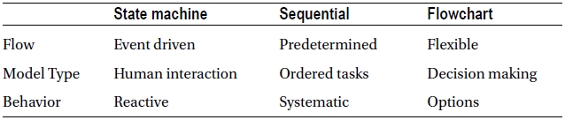
Even with sequential workflows, there were limitations for modeling processes—precisely because sequential workflows execute activities one after another and follow a top-down execution flow. With the release of WF4, the flowchart control flow was introduced into WF for authoring workflows. It added the necessary flexibility for modeling execution flow using decisions instead of a top-down execution flow or looping constructs through sequential workflows. In fact, WF4 removed the idea of having workflow-type templates for building workflows and replaced them with state machine and flowchart workflow activities, thus ending the limitations imposed by integrating state machine, sequential, and flowchart control flows within the same workflow. Table 5-1 categorizes the different control flows found in WF4 and 4.5 around flow, modeling type, and behavior.
Table 5-1. WF4-4.5 Control Flows
The flexibility that flowcharting confers hinges on being able to flow back up to activities that have been executed previously based on conditions used for making decisions within a business process. This flexibility provides a modeling approach for building workflows using WF, which is parallel to how people usually visualize business logic. Therefore, modeling a flowchart workflow in WF yields so detailed a picture that it can also serve as a medium for communicating development requirements to non-technical people.
This chapter will walk you through different scenarios for building and implementing flowchart control flows within workflows as well as communication between workflow and their hosting applications. While demonstrating the flowchart control flows for building workflows, I will use the out-of-the-box activities within WF to show how different patterns of logic can be modeled, taking advantage of the features provided by WF activities.
Flow Activities
WF4 provides three activities for building a flowchart control flow. At first glance it might seem that there is more involved, but because a flowchart in WF is a type of control flow that leverages the same WF activities as any other workflow, it doesn’t take much to model a business process as a flowchart. The three activities for building flowchart control flow are
- Flowchart: Provides the flowchart control flow itself when applied to the WF designer for building a workflow.
- FlowDecision: Establishes the mechanics for making decisions throughout a workflow by provisioning two distinctly opposite transitions where only one of the transitions can execute based on a decision.
- FlowSwitch: Predefines transitions based on a matched value associated with a transition, for coordinating work to other activities. Only one transition can be executed based on the matched value.
Figure 5-1 shows the Flowchart section within the activity toolbox.
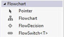
Figure 5-1. Flowchart secion within the activity toolbox
Flowchart
The Flowchart activity represents the foundation for building a flowchart control flow within the WF. Once it is added to the WF designer, it sets the stage by providing the starting point for a flowchart control flow (see Figure 5-2).
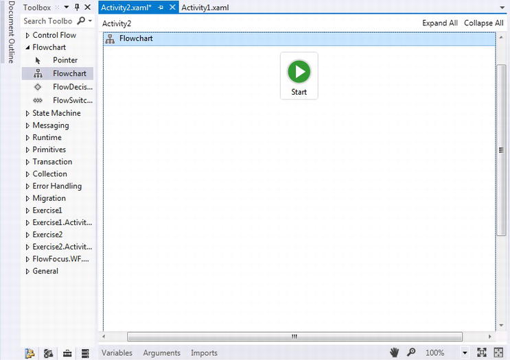
Figure 5-2. Flowchart activity
A Flowchart activity must be added first (Figure 5-2), before either a FlowDecision or FlowSwitch activity can be added. A new feature that WF4.5 provides is a ValidateUnconnectedNodes property that can be viewed within the Properties window in Visual Studio (see Figure 5-3).
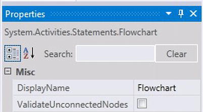
Figure 5-3. ValidateUnconnectedNodes property
By default, the ValidateUnconnectedNodes property is set to false, so the workflow in Figure 5-4 will compile when building a workflow project within which it is included.
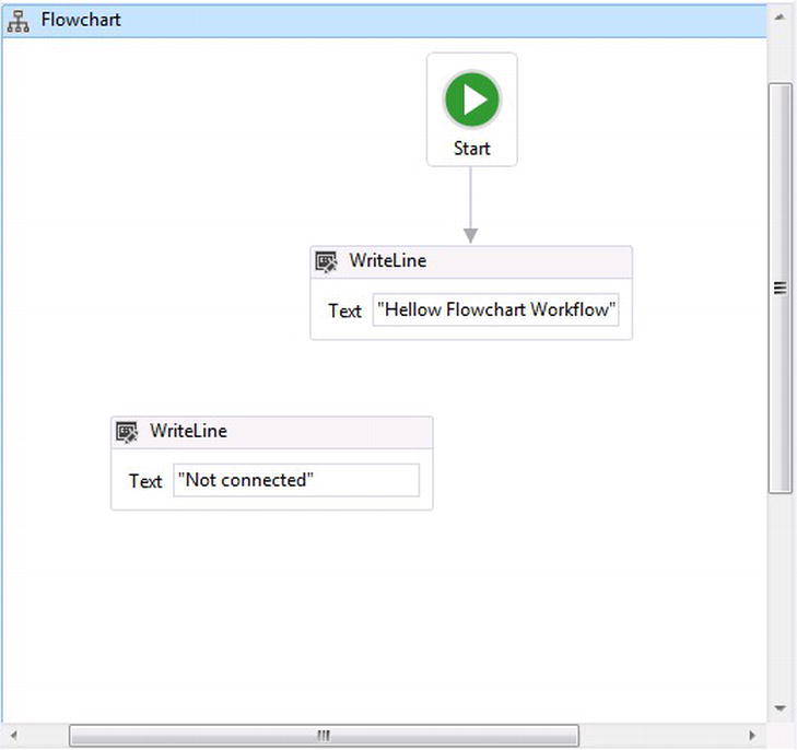
Figure 5-4. Unconnected activity nodes
The ValidateUnconnectedNodes property was added because sometimes workflows that are built at design time are incomplete but nevertheless will compile and run. Checking the property’s checkbox for ValidateUnconnectedNodes tells WF to check and make sure that a flowchart workflow does not have any unconnected activity nodes. If it does, WF will indicate at design time that there are one or more unconnected nodes between activities.
FlowDecision
The FlowDecision activity can be added within a Flowchart activity (Figure 5-5) and represents the decision-making logic that will be implemented within a workflow.
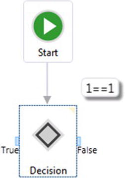
Figure 5-5. FlowDecision activity
After a FlowDecision activity has been added to a workflow, there are three unique properties that need to be set:
- Condition
- FalseLabel
- TrueLabel
The Condition property uses an expression that returns a Boolean to determine a decision that needs to be processed. FalseLabel and TrueLabel represent the two and only two transitions that can be executed based on the returned Boolean value from the expression. The condition property for the FlowDecision activity in Figure 5-5 indicates that the expression 1==1 has been set and that there are two possible transitions that represent the possible flow, which in this case will always be True. An interesting behavior in this case is that the activity can afford to only use one transition, but only when ValidateUnconnectedNodes is unchecked, since the expression 1==1 will always equal true. The FalseLabel and TrueLabel properties have the default text values of True and False, however they can be changed for a more descriptive representation for the decision that is being made. WF4.5 also adds a new property called DisplayName to the FlowDecision activity, so the FlowDecision activity can also be changed to be more descriptive about the type of decision being made. See Figure 5-6.
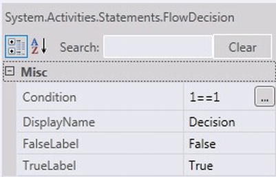
Figure 5-6. FlowDecision properties
To demonstrate this, a FlowDecision activity is used to verify if a WF variable, representing a person's age and defined as an integer named varAge. The FalseLabel and TrueLabel properties representing the two transitions have also been changed to “65 or older” and “Under 65” (see Figure 5-7).
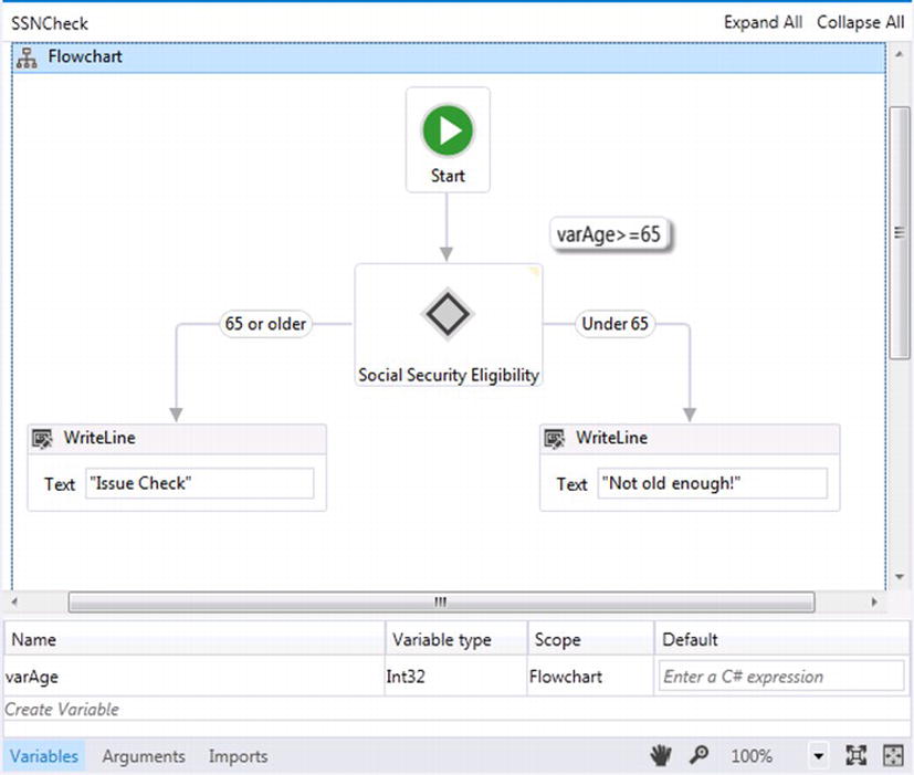
Figure 5-7. Using the Decision activity
The last activity within the flowchart palette is the FlowSwitch <T> activity. The logic it performs closely mimics the coding construct of a switch statement represented within most programming languages. After a FlowSwitch activity is added to the designer canvas of a flowchart workflow, the value type for the object that will be used to guide the possible predefined flows of the workflow must be selected (see Figure 5-8).
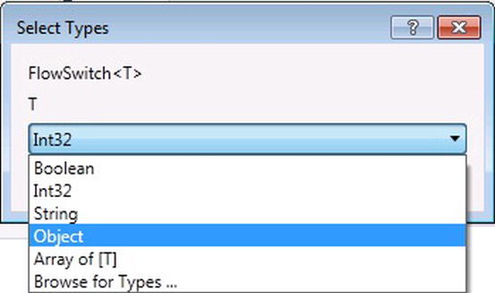
Figure 5-8. FlowSwitch type selection
After the value type for the FlowSwitch is set, the Expression property for the activity needs to be set; it will return the value type. The expression’s return value must match the value type defined while adding the activity to the WF designer. The Expression Editor in Figure 5-9 demonstrates using a custom WF variable, varCustomerRating, for a return type of Int32 that returns the number representing a customer’s rating between 1 and 5.
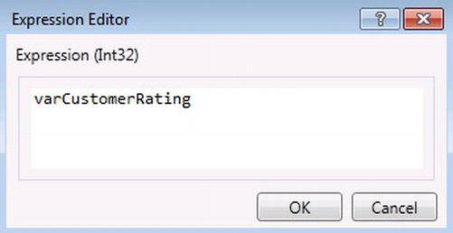
Figure 5-9. Expression used for returning the value type
Finally, when adding the first transition to the FlowSwitch, it is represented as the default transition, which means that if there is no match for any of the other transitions for execution, the default transition is designated to be executed. Figure 5-10 shows the results for setting up a simple workflow using the FlowSwitch activity and transitioning the flow based on the returned value from the expression in Figure 5-9.
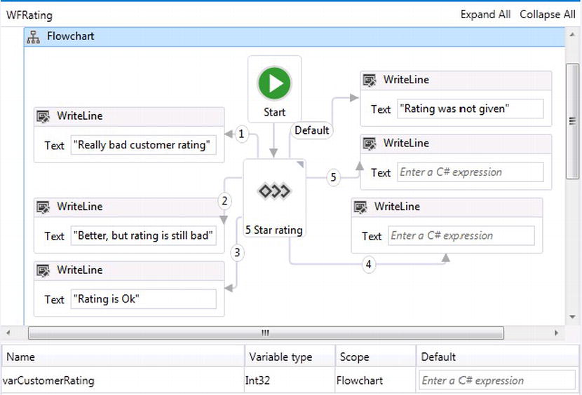
Figure 5-10. Demonstrating the default and rating transitions
BUILDING A FLOWCHART WORKFLOW
This exercise will walk you through modeling the business process for retrieving a customer’s order from the database, using a flowchart workflow, and totaling the amount owed based on the customer’s order. The data plumbing for the workflow will take advantage of the Entity Framework’s Code First model, allowing you to generate the database and wire the data plumbing through code.
![]() Note By the time this book is published, Entity Framework 5 will probably be released and can be used instead of EF4.3 in this exercise.
Note By the time this book is published, Entity Framework 5 will probably be released and can be used instead of EF4.3 in this exercise.
- Open Visual Studio 2012 and create a new Project
- Select the Workflow template to see a list of installed workflow templates.
- Select workflow console application and name it Chapter5.FlowChart.
- Rename the workflow console application to Exercise1. Delete the workflow that is included with the project and add a new activity named wfCustomerOrders.xaml.
- Right-click on the solution and add new Visual C# class library. Name it Chapter5.DataModel. This project will handle all of the database plumbing used within the solution.
- Rename the file Class1.cs that was added by default to Customer.cs.
- Paste the following code into the Customer.cs file:
using System;
 using System.Collections.ObjectModel;
 using System.Collections.Generic;
 using System.Text;
 using System.Threading.Tasks;
 using System.ComponentModel.DataAnnotations;
 namespace Chapter5 .DataModel
 {
     public class Customer
     {
         public Customer()
         {
             CustomerOrders =  new Collection <Order> ();
         }
         [Key]
         public int CustomerId { get; set; }
         public string CCNumber { get; set; }
         [Required]
         public string FirstName { get; set; }
         [Required]
         public string LastName { get; set; }
         public virtual ICollection <Order>  CustomerOrders { get; set; }
     }
     public class Customers : Collection <Customer>
     {
     }
} - Add a new class to the Chapter5.DataModel and call it Order.cs. Paste the following code into the file:
using System;
 using System.Collections.ObjectModel;
 using System.Collections.Generic;
 using System.Linq;
 using System.Text;
 using System.Threading.Tasks;
 using System.ComponentModel.DataAnnotations;
 namespace Chapter5 .DataModel
 {
     public class Order
     {
         public Order()
         {
             LineItems =  new Collection <OrderLineItem> ();
         }
         [Key]
         public int OrderId { get; set; }
         [Required]
         public int CustomerId { get; set; }
         [Required]
         public DateTime DateOrdered { get; set; }
         [Required]
         public virtual ICollection <OrderLineItem>  LineItems { get; set; }
     }
} - Add new class to the Chapter5.DataModel and call it OrderLineItem.cs. Paste the following code into the file:
using System;
 using System.Collections.Generic;
 using System.Linq;
 using System.Text;
 using System.Threading.Tasks;
 using System.ComponentModel.DataAnnotations;
 namespace Chapter5 .DataModel
 {
     public class OrderLineItem
     {
         [DatabaseGenerated(DatabaseGeneratedOption.Identity)]
         public int LineItemId { get; set; }
         [Key]
         public int OrderId { get; set; }
 [Required]
         public string LineDescription { get; set; }
 [Required]
         public string SKU { get; set; }
 [Required]
         public Decimal? Price { get; set; }
     }
 }
At this point you have built the Plain Old CLR Objects (POCO) that will be used to manage customers and their orders. The code that was pasted in might look different to developers who are not used to using Microsoft’s Entity Framework for object-relational mapping (ORM). However, later I will give a detailed description for what is going on within the POCO classes that were just added.
Entity Framework (EF) has been around for a number of years now and is used for building and managing data layers within an application and the tables and relationships for data within SQL Server. EF’s Code First approach lets developers use code to handle the building of databases and application integration of an application and a SQL Server database. EF’s Code First approach may not be appropriate to use as a standard for all software projects, but huge benefits are gained within projects that are built from the ground up and when used within the initial stages for building architecture. The next steps will set up the code that will be used to build the database using EF’s Code First.
The version of EF used in this exercise it Entity Framework 4.3, and if it is not already installed with Visual Studio 11, it can be downloaded via NuGet. NuGet is an extension to Visual Studio that assists in downloading companion frameworks for writing software within Visual Studio. By default Entity Framework 4.3 will use SQL Server 2008 R2 Express, which can be downloaded and installed from www.microsoft.com/sqlserver/en/us/editions/express.aspx to build the database required in this exercise. - Add new class to the Chapter5.DataModel and call it Ordering.cs. Paste in the following code into the file:
using System;
 using System.Collections.Generic;
 using System.Linq;
 using System.Text;
 using System.Threading.Tasks;
 using System.Data.Entity;
 namespace Chapter5 .DataModel
 {
     public sealed class Ordering : DbContext
     {
         public DbSet <Order>  Orders { get; set; }
         public DbSet <Customer>  Customers { get; set; }
         protected override void OnModelCreating(DbModelBuilder modelBuilder)
     {
             // Customer can have many Orders.
         modelBuilder.Entity <Customer> ()
                 .HasMany <Order> (customer =>  customer.CustomerOrders);
             // Order can have many LineItems.
         modelBuilder.Entity <Order> ()
                 .HasMany <OrderLineItem> (order =>  order.LineItems);
             // LineItems contains a composite key.
         modelBuilder.Entity <OrderLineItem> ()
             .HasKey(p =>  new { p.OrderId, p.LineItemId });
         }
     }
} - Add a new Unit Test project to the solution by right-clicking the solution and selecting New Project. Select the Test template that is represented under the Visual C# section (see Figure 5-11).
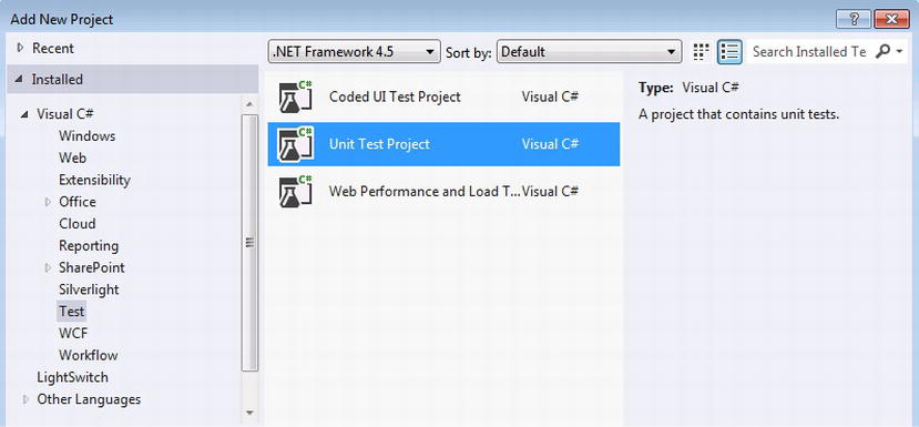
Figure 5-11. New Test Project
- Rename the new test project as TestOrders. This project will test the EF Code First implementation and will also load customers and orders for the customers into the database.
- By default the test project comes with a UnitTest1.cs file that has the stubs used for writing unit tests. Replace the existing file with the following code:
using System;
 using System.Text;
 using System.Collections.ObjectModel;
 using System.Collections.Generic;
 using Microsoft.VisualStudio.TestTools.UnitTesting;
 using Chapter5 .DataModel;
 using System.Data.Entity;
 using System.Linq;
 namespace Chapter5 .Testing
 {
     [TestClass]
     public class UnitTest1
         {
         [TestMethod]
         public void TestGetOrders()
 {
             using (var ordering =  new Ordering())
             {
                 var custs =  from cust in ordering.Customers
            select cust;
                 var customers =  new Collection <Customer> ();
                 foreach (var c in custs)
                 {
                     customers.Add(c);
                 }
             }
         }
         [TestMethod]
         public void TestCodeFirst()
         {
             Database.SetInitializer(
                  new DropCreateDatabaseIfModelChanges <Ordering> ());
             using (var ordering =  new Ordering())
             {
                 ordering.Database.Initialize(false);
                 var customer =  new Customer
                 {
                     FirstName =  "John"
                     ,
                     LastName =  "Smith"
                 };
                 var order =
                     new Order
                     {
                         DateOrdered =  DateTime.Now
                     };
                 order.LineItems.Add(new OrderLineItem
                         {
                             LineDescription =  "Widget 1",
                             Price =  5.50m,
                             SKU =  "fff-321-gfsf"
                         });
                 order.LineItems.Add(new OrderLineItem
                 {
                          LineDescription =  "Widget 2",
                          Price =  4.10m,
                          SKU =  "AAA-234-asdf"
                 });
                 order.LineItems.Add(new OrderLineItem
                 {
                     LineDescription =  "Widget 3",
                     Price =  10.10m,
                     SKU =  "BBB-321-j7df"
                 });                customer.CustomerOrders.Add(order);
                 ordering.Customers.Add(customer);
                 ordering.SaveChanges();
             }
         }
     }
} - Some references within the projects need to be made, so we can start by adding the references to the Chapter5.DataModel. Once NuGet is installed, check the project to make sure that Entity Framework 4.3 is installed. Figure 5-12 demonstrates how to right-click on the project and select “Manage NuGet Packages.”
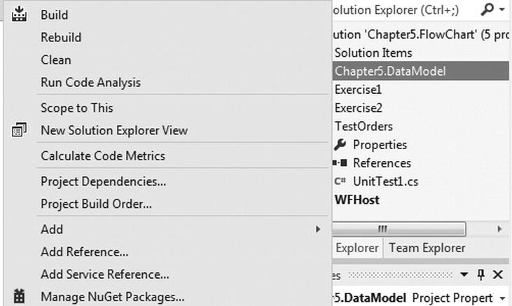
Figure 5-12. Managing NuGet packages
Check to see if Entity Framework 4.3 is installed by viewing the installed NuGet packages, illustrated in Figure 5-13. If it is not installed, an Install button can be pressed to download Entity Framework 4.3.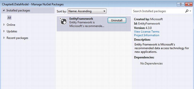
Figure 5-13. Checking if EntityFramework 4.3 is installed
- Right-click References for the project and make sure to add references to System.ComponentModel.DataAnnotations, System.Data.DataSetExtensions, and System.Data.Entity. The reference list should look like Figure 5-14.
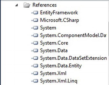
Figure 5-14. Chapter5.DataModel references
- After adding the references, build the project by right-clicking on the project and selecting Build.
Add a reference to the Entity Framework 4.3 within the test project TestOrders by either following the same steps for adding it via NuGet or adding it to the test project by using the file path for the EntityFramework referenced within the Chapter5.DataModel project, selecting References, and browsing to the same file path to add the reference to Entity Framework 4.3. The TestOrders reference list should look like Figure 5-15.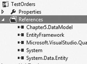
Figure 5-15. TestOrders references
- Now that the references have been added, right-click the project and select Build.
- After the project successfully builds, open up the UnitTest1.cs file within the TestOrders project.
- Put the cursor on the test method TestCodeFirst() and then go to the top menu for visual studio and click on Test
 Run Tests in Current Context. This will run the test that will create the customer order and line items. To test that the records have been successfully created, you can either look at the database using SQL Server Management Studio or add a breakpoint by clicking the grey boundary of the code editor on the same line as the foreach statement within the test method TestGetOrders().
 - This time put the cursor on the test method TestGetOrders(), and then go to the top menu for Visual Studio and click on Test Debug Tests in Current Context. This will run the test method in debug mode, allowing the code to rest of the breakpoint. Press F10 to cycle through the ForEach statement, indicating that a customer has been loaded into the database.
At this point, the data access layer is built and you can start building the workflow that is going to retrieve the customer order and line items, and build the logic for tallying up the total cost for the line items. To get the customer order, the workflow will rely on using a code activity that will implement the same code used to test that the customer record had been added to the database. - Right-click the workflow project Exercise1 and add a new folder called Activities. Right-click the folder and add a new class file. Name the file GetCustomeOrders.cs and replace the code with the following code:
using System;
 using System.Activities;
 using System.Collections.Generic;
 using System.Linq;
 using System.Text;
 using System.Threading.Tasks;
 using Chapter5 .DataModel;
 using System.Collections.ObjectModel;
 namespace Exercise1.Activities
 {
     public class GetCustomerOrders:CodeActivity
     {
         [RequiredArgument]
         public OutArgument <Customers>  outCustomers { get; set; }
         protected override void Execute(CodeActivityContext context)
         {
             using (var db =  new Ordering())
             {
	        db.Configuration.LazyLoadingEnabled =  false;
                 var custs =  db.Customers.Include("CustomerOrders.LineItems");
                 var customers =  new Customers();
                 foreach (var c in custs)
                 {
                     customers.Add(c);
                 }
                 // Reassign the argument.
                 context.SetValue(outCustomers,customers);
             }
         }
     }
} - There are two references that need to be made for the workflow project Exercise1. The first reference needs to add EntityFramework and the second is Chapter5.DataModel. Right-click on the Exercise1 project and select Build. After a successful build, the code activity GetCustomerOrders should appear in the Exercise1.Activties section of the toolbox.
- Now the flowchart workflow is ready to be modeled. Double-click the Workflow1.xaml file to view the workflow designer. Next, drag a Flowchart activity from the toolbox onto the designer canvas. This sets the foundation for the flowchart workflow. While the workflow has focus and the Properites window is visible, check the ValidateUnconnectedNodes so all activity connections are validated.
- Drag and drop the custom code activity GetCustomerOrders onto the designer canvas and while dragging the activity, lightly brush it close to the left side of the start activity on the workflow. This behavior will cause the nodes to appear on the start activity and will automatically connect the two activities once it is dropped. Figure 5-16 represents how the workflow should look at this point.
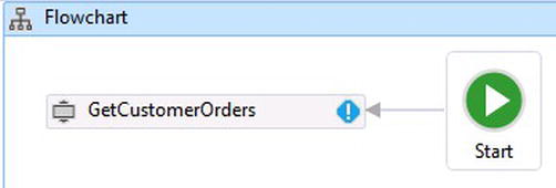
Figure 5-16. GetCustomerOrders
GetCustomersOrders activity has an OutArgument called OutCustomers and because it is not set, the exception notification is visible on the activity. Viewing the Error List gives the details to the exception (that it must be set when using the activity within a workflow). A WF variable needs to be created to receive the collection of customers that the activity will return. See Figure 5-17.
Figure 5-17. Out argument required exception
- Add a new WF variable for the workflow by clicking the Variable tab on the bottom left of the workflow. Set the name to varCustomers. The variable type is a custom type, Customers, and it is referenced in the Chapter5.DataModel project (see Figure 5-18). Click the drop-down box for the variable type and select Browse for Types.
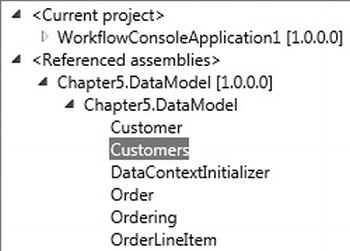
Figure 5-18. Customers type
- Select Customers for the variable type and set the default value for the variable to new Customers(). Make sure that the scope is set to Flowchart (see Figure 5-19).

Figure 5-19. Creating the variable to hold customers
- Add the new WF variable varCustomers to the GetCustomersOrders by selecting the activity and viewing its properties within the Properties window. Select the button for outCustomers and type varCustomers into the textbox. After clicking OK, the exception notification for the activity will go away.
- Drag a FlowDecision activity from the Flowchart section of the toolbox. And brush it close to the GetCustomersOrders activity so it can auto-connect the activities. While the FlowDecision activity has focus, make sure the Properties window is visible.
- Set the Condition by pressing the button and adding varCustomers! = null&&varCustomers.Count> 0. This Condition will return a Boolean that will determine the flow for activity. Click OK.
- Change the FalseLabel property to No Orders and the TrueLabel to Orders Exist.
- Drag a WriteLine activity from the toolbox and brush the right side of the FlowDecision activity exposing the No orders node so it can auto-connect. Add There are no new customer orders inside the textbox for the WriteLine activity.
- Drag the ForEach <T> activity from the toolbox and brush it to the left side of the FlowDecision activity to auto-connect the Orders Exist node with the ForEach <T> activity.
- Click on the ForEach <t> activity to set configure its properties. Click the drop-down box for the TypeArgument property and select Browse for Types. Expand Chapter5.DataModel as illustrated in Figure 5-18 and select Customer as the argument type. At this point the workflow should resemble Figure 5-20.
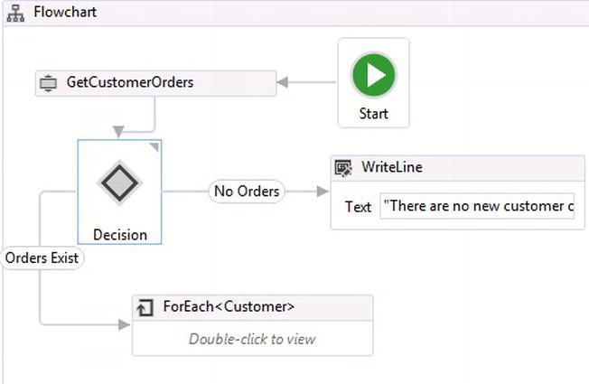
Figure 5-20. Customer orders workflow
- Double-click the ForEach activity, which will make the body for the activity accessible. There are two textboxes at the top of the activity. Add cust as the value for the textbox on the left and the LINQ expression from c in varCustomers select c for the value of the textbox on the right (see Figure 5-21).

Figure 5-21. Textbox value
- Drag another ForEach <T> activity within the body of the existing ForEach <T> activity. Set the TypeArgument property to Chapter5.DataModel.Order. Add order as the value for the textbox on the left and cust.CustomerOrders for the value of the textbox on the right (see Figure 5-22).

Figure 5-22. Textbox value
- Drag another ForEach <T> activity within the body of the last ForEach <T> activity that was added. Set the TypeArgument property to Chapter5.DataModel.OrderLineItem. Add lineItem as the value for the textbox on the left and order.LineItems for the value of the textbox on the right (see Figure 5-23).

Figure 5-23. Textbox value
- Drag an Assign activity within the body of the ForEach <T> activity that was just added.
- Drag a WriteLine activity just underneath the last ForEach <T> activity. The designer will automatically create a new Sequence activity so the WriteLine activity can be dropped.
- Before the Assign activity can be configured, another WF variable needs to be added that has scope within the auto-generated Sequence activity.
- Click on the Variable tab and add a WF variable named varTotalPrice. Select Browse for Types and set the VariableType to System.Decimal and set the scope to Sequence.
- Click on the Assign activity and within the Properties window, set the To property to varTotalPrice and the Value property to varTotalPrice + lineItem.Price.value.
- Click on the WriteLine activity and set the Text property to
string.Format("Order for {0} has a total cost of {1}",←
At this point the composite activity built from steps 35–43 should look like Figure 5-24.
cust.FirstName + " " + cust.LastName,string.Format("{0:C}",varTotalPrice))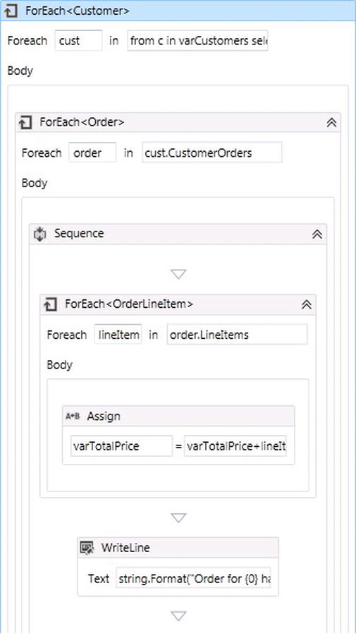
Figure 5-24. Nested ForEach <T> activities
- Open up the Program.cs file and replace the existing code with the following code:
using System;
 using System.Linq;
 using System.Activities;
 using System.Activities.Statements;
 namespace Exercise1
 {
    class Program
     {
         static void Main(string[] args)
         {
             // Create and cache the workflow definition
             Activity workflow1 =  new wfCustomerOrders();
             WorkflowInvoker.Invoke(workflow1);
             Console.ReadKey();
         }
     }
 }
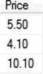
Remember that you already created the test data that the workflow will use. There should be one order for John Smith with three line items within the order with the following prices:
Make sure that Exercise1 is set as the startup project and press F5 to run the solution. Once everything builds successfully and the workflow runs to completion, the results are displayed within the console window (see Figure 5-25).
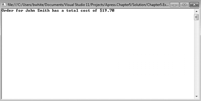
Figure 5-25. Order totaled for customer
Using Entity Framework with WF
Entity Framework is a great data technology that can be used with WF for handling the data plumbing code required to interact with SQL Server. In fact, the previous exercise demonstrated how EF4.3 can be used as a Code First approach for writing code that generates a database within SQL Server Express 2008 R2 and the data access code for inserting and retrieving order information for a customer. I want to quickly answer some of the most obvious questions based on the code that was used in the exercise pertaining to EF.
Three POCO classes were built as the entities used for a customer order. The classes are nothing out of the ordinary, other than they implement additional EF namespaces for added EF functionality. The first EF implementation to point out is the namespace of System.ComponentModel.DataAnnotations. DataAnnotations allowed the entity’s properties to be decorated indicating the following:
- Required: The property cannot be saved to the database with a value of null.
- Key: The property indicates that it is either part of a composite key or is the primary key.
- DatabaseGenerated (DatabaseGeneratedOption.Identity): Indicates the property is seeded as an identity property, therefore the value will be generated within the database table.
If you have worked with POCO objects, some of the implementation for the Ordering.cs file probably is not too far off from other EF implementations you have experienced. Except with Code First, the entity relationships are no longer described using the EF designer canvas. This is a good thing because those files can become hard to manage over time and as the model gets bigger. Instead, Code First describes all of the relationships through code, using the same class that inherits from DbContext. The difference is lies within protected override void OnModelCreating(DbModelBuilder modelBuilder). This override method is called first to mash up the relationships described through code. As crazy as it sounds, that is all that is required for using POCO objects and to have the data access code and database tables generated. The code within the unit tests for building the customer and order record is no different than any other call using EF. Figure 5-26 shows the tables that were generated.
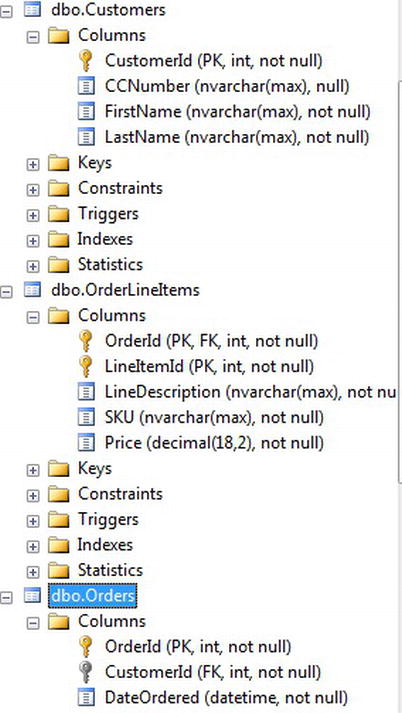
Figure 5-26. Generate tables through EF Code First
The ForEach <T> activity was also used in Exercise 1, so I want to cover in more detail why it was used. The ForEach <T> activity is used to loop through enumerable objects just like the coding construct of a ForEach loop. The goal through WF, though, is to handle the same functionality declaratively. In Exercise 1, three different ForEach <T> activities were used to loop through
- The number of customer records
- The number of orders per customer
- The number of line items per order
Most programmers might find that wiring up the ForEach <T> activity is not as intuitive when compared to the writing ForEach loops in code, so here is what you need to know. There are two properties that need to be set:
- TypeArgument: The type returned from each iteration
- Values: Expression that will return a collection for the iteration type. This includes WF variables, arguments, or LINQ statements for narrowing down collection values.
The first ForEach <T> activity that was added in Exercise1 was used to iterate through the customers objects that were returned from the database, so the ForEach <T> properties set were as follows:
- TypeArgument: Chapter5 .DataModel.Customer
- Values: from c in varCustomers select c or just varCustomers
Double-clicking the activity will show the two text boxes that resemble an actual ForEach coding construct in C#. Figure 5-27 shows that the left textbox holds the name of the Customer object named cust, which is set to a Customer object for each iteration of the loop. The textbox on the right is where the collection of customers is set using the code from c in varCustomers select c, which grabs the customers from the WF variable that was set using the OutArgument of the GetCustomerOrders activity.
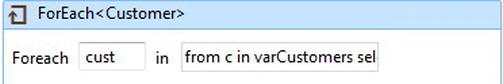
Figure 5-27. Intializing each customer object within a WF variable
The body of the ForEach <T> activity is where logic can be added to handle each iteration. A second ForEach <T> activity is added within the parent ForEach <T> activity for iterating further within a customer object, as the pattern starts to reflect a common practice of a nested ForEach coding construct (see Figure 5-28).
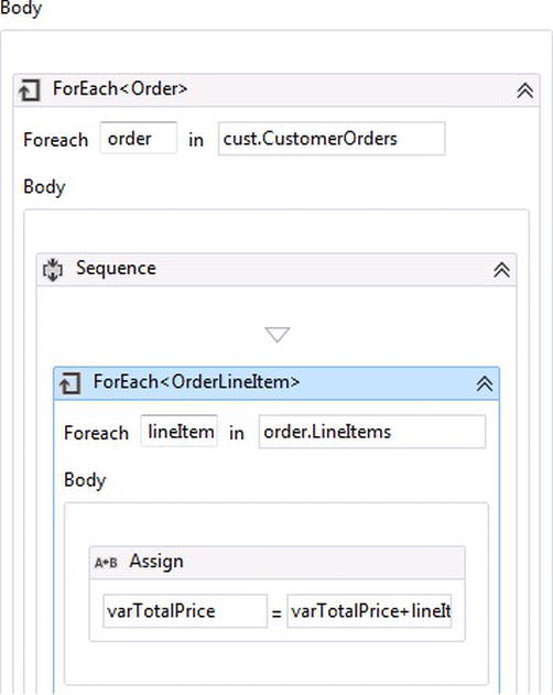
Figure 5-28. Nested ForEach <T> activity
The ForEach <T> properties set for iterating through the orders object are
- TypeArgument: Chapter5.DataModel.Order
- Values: cust.CustomerOrders
The TypeArgument property indicates that an order will be returned with each iteration for a customer’s order, represented as cust.
A third ForEach <T> activity is added within the body of the existing nested ForEach <T> activity to iterate through each of the line items of an order. The properties set for iterating through the OrderLineItems object are
- TypeArgument: Chapter5.DataModel.OrderLineItem
- Values: order.LineItems
The TypeArgument property indicates that a lineItem will be returned with each iteration for an order represented as order. A Sequence activity is used as a container for the ForEach <T> activity because with each iteration of an order’s line item, an Assign activity is required to calculate the total charge for the order. As a result, the WF variable varTotalPrice is used to add the price for each line item (see Figure 5-28).
Of course the logic represented using the nested ForEach <T> activities could have been handled differently either by using C# code within a code activity or by calling code outside of the workflow, but the goal for WF is to declaratively handle logic for an order on the fly—also giving the power to others who may not be technical enough to write custom code.
![]() Tip I mentioned that WF4.5 has a new Flowchart control flow property called ValidateUnconnectedNodes that checks that unconnected nodes within the workflow are set. At first glance, it might make sense that this should be set, but instead think of it as an option for added flexibility while building a workflow. For instance, you might want to change up the workflow, so unchecking the property will allow activities to be disconnected from others but remain on the designer canvas without validation, so they can be reconnected later if needed. It might be a good idea to check the property in the beginning for authoring a flowchart, but later it can be unchecked while changing up the workflow.
Tip I mentioned that WF4.5 has a new Flowchart control flow property called ValidateUnconnectedNodes that checks that unconnected nodes within the workflow are set. At first glance, it might make sense that this should be set, but instead think of it as an option for added flexibility while building a workflow. For instance, you might want to change up the workflow, so unchecking the property will allow activities to be disconnected from others but remain on the designer canvas without validation, so they can be reconnected later if needed. It might be a good idea to check the property in the beginning for authoring a flowchart, but later it can be unchecked while changing up the workflow.
Flowchart Composite Activities
One of the cool factors in WF is the ability to take declarative logic and use it more than once. As developers, we already have this feature in code, where objects can be defined using classes and then compiled for reuse within other frameworks or applications. The same applies to WF and composite activities, which are simply more than one activity working together.
I know what you are thinking! “Then what is a workflow?” Well, a workflow is essentially a composite activity but usually at a much grander scale. A good practice for writing code is to keep it simple and modular. The same applies to composite activities. You want them to focus on a certain piece of logic. When they start becoming too large, that might be a good time to look at refactoring.
A great example for building a composite activity is the logic used in Exercise 1 for calculating total cost for an order, except let’s give the activity a little more functionality. Instead of just calculating cost, the activity will also do the following:
- Calculate total cost for an order with tax.
- Return what the tax amount was for the order.
To make things even more interesting, I will demonstrate using the FlowSwitch activity to calculate tax for an order based on certain states within the United States. Since the ordering system takes orders online orders, tax is collected on orders that are shipped within the state where the company resides. So if your fictional company of ACME is located within Florida and an order is to be shipped in Florida, the order will be taxed.
The first thing to do is to take the nested ForEach <T> activities used in Figure 5-24 and make them into their own composite activity. A new activity can be added to a project by right-clicking on a project and selecting New Item. Under the installed workflow templates there is an Activity template that can be selected, as illustrated in Figure 5-29.
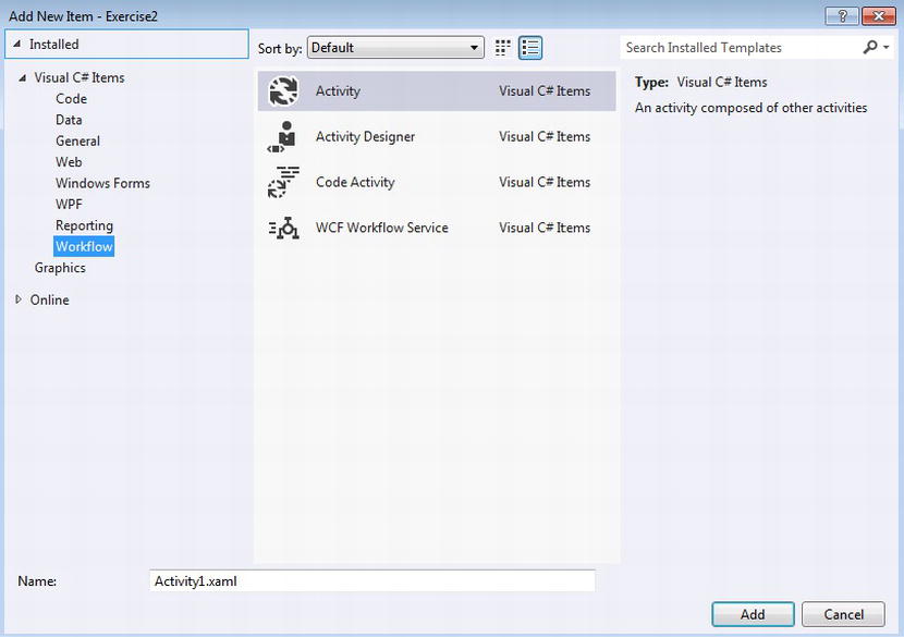
Figure 5-29. Adding a new XAML activity
The new activity will be created from existing XAML. Note that the extension for the default activity file name is XAML as well. After the new activity is added to the project, activities can be added to the WF designer, but instead of adding activities from the toolbox, the ForEach <T> activities used earlier need to be added. Simply select the parent ForEach <T> activity used for iterating though customers, right-click on the tab of the activity, and select Copy (see Figure 5-30).
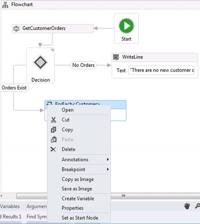
Figure 5-30. Copying a composite activity
After copying the composite activity, it can be pasted into the new activities designer canvas. Once it is pasted in, the nested ForEach <T> activities are exposed visually. Right away the expression used to get customers is invalid, and the composite activity needs an argument so it can receive data. A new argument can be created by clicking on the Arguments tab for the workflow. Figure 5-31 shows the new argument created for the composite activity. The new argument’s direction is In and its argument type is Chapter5 .DataModel.Customers. The Values property of for the parent ForEach <T> activity can now be changed to argInCalcCustomers as a generic way for handling the customers object within the activity.

Figure 5-31. New composite activity in argument
Currently the activity calculates the total price for the order based on the order’s line items and then sends a string to the console (see Figure 5-32).
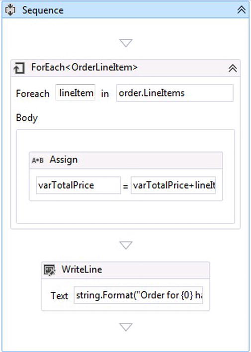
Figure 5-32. Calculating total price and writing to the console
To calculate the total price for the order and the tax amount, the activity needs to be changed around slightly, as does the Order object. The following three properties were added to the Order object:
[NotMapped]
Public decimal Tax { get; set; ]

[NotMapped]
Public decimal TotalPrice { get; set; ]

[Required]
Public string ShippingState { get; set; ]
Instead of using the WF variable varTotalPrice, the properties TotalPrice and Tax will hold the appropriate values. These properties are not important as far as the database is concerned, so they are marked with the attribute [NotMapped] so Entity Framework is not aware of them. The ShippingState property will be used later for checking if tax needs to be calculated for the order and at what percent.
To calculate the order’s total price, the workflow can utilize the new TotalPrice property for an order instead of the WF variable, varTotalPrice. Also, the WriteLine activity is no longer needed. Instead, a Flowchart activity is added to calculate the State tax. The Assign activity in Figure 5-33 can now calculate the total price of an order based on the argument that was passed in, without having to build additional variables. Next, the composite Flowchart activity represented in Figure 5-33 needs to be built to calculate tax if required.
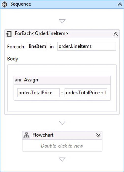
Figure 5-33. Calculating total price based on the argument passed in
So hypothetically, your fictitious company has stores in the specific States, with the corresponding tax rates, shown in Table 5-2.
Table 5-2. States and tax rates
| State | Tax Rate |
|---|---|
| Florida | 7% |
| Georgia | 3& |
| Alabama | 5% |
Because there are more than two options for taxing and ordering, and because there could be more in the future, a FlowSwitch activity can be used to model the flow for taxing an order. Figure 5-34 represents how this can be done. Notice that annotations were added for the workflow and each of the activities in Figure 5-34, which is a feature of WF4.5 that represents the logic for what needs to be performed.
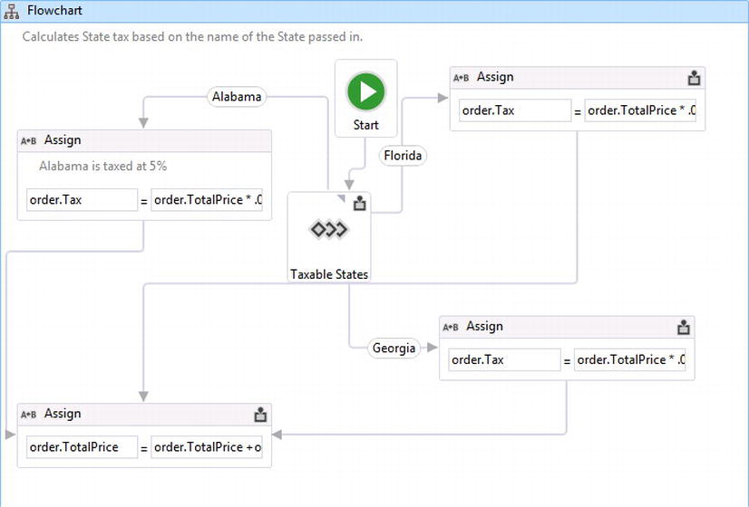
Figure 5-34. Flowchart activity for handing state tax logic
Annotations can be visible, as in Figure 5-34, or hidden where only a little icon, located in the top right of the activity, can be seen indicating that an annotation exists. Stepping back out of the Flowchart activity, annotations are visible for giving a description for what logic a composite activity performs (see Figure 5-35).
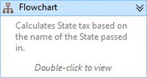
Figure 5-35. External view of an activity’s annotation
To add activities within the Flowchart activity, double click on it, as Figure 5-35 indicates. This is just like starting a new Flowchart activity except it is now a composite activity or a child activity. From the toolbox, a new FlowSwitch activity is needed to coordinate the possible flows for taxing based on a state, and the value type that will be returned from the expression property will be a String. The Expression property is set to order.ShippingState, therefore the shipping state supplied with an order can be matched based on its literal value (see Figure 5-36).
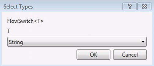
Figure 5-36. Setting the FlowSwitch activity Type
Only three states (Florida, Georgia and Alabama) need to collect taxes, so if a shipping state is blank or not equal to one of these states, taxes will not be calculated. The Expression property for the FlowSwitch activity is set to order.ShippingState; because the Flowchart activity is a composite activity, it also has scope to the order object used in the parent ForEach <T> activity, shown in Figure 5-33.
Four Assign activities are also added. A shortcut for adding four of the same activities is to drag the first one from the toolbox, copy the activity added using the shortcut keys Ctrl-C, and then pressing Ctrl-V four times to paste it within the WF designer (see Figure 5-37). Three of the Assign activities are used to calculate taxes for each of the three states and the fourth Assign activity adds the appropriate tax amount set within the order.Tax property to the order.TotalPrice property.
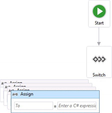
Figure 5-37. Cutting and pasting Assign activities
The three Assign activities that set the state taxes are similar (apart from the tax rate), so the To property is set to order.Tax and the Value property for each state is as follows:
- Florida: Order.TotalPrice * .07m
- Alabama: Order.TotalPrice * .05m
- Georgia: Order.TotalPrice * .03m
The fourth Assign activity calculates the overall total price by adding any taxes to the total cost for the order based on the line items. The To and Value properties values are as follows:
- To : order.TotalPrice
- Value : order.TotalPrice + order.Tax
And the other three Assign activities that calculate the state’s taxes can all be transitioned to it (see Figure 5-37).
After setting up the Assign activities, the FlowSwitch activities cases are wired up with the appropriate state tax rates. This is done by connecting nodes from the FlowSwitch activity to each of the Assign activities used to calculate the taxes. Remember that the first node created from the FlowSwitch activity will try to assign it as the default case, so unchecking the IsDefaultCase property will allow the Case property to be visible so it can be modified to a literal state name. After a transition is created, Table 5-2 represents the state names in relation to the tax rates that are set up within Figure 5-34. Once the project is compiled, the CalculateOrder activity will show up within the toolbox for the project and it can then be used for other workflows.
Bookmarks for Flowchart Workflows
So far I have focused on building flowchart workflows, but just like state machine workflows, we need to be able to communicate with them. Earlier I demonstrated using WF bookmarks to communicate with state machine workflows and the hosting application using workflow application by adding the bookmarks within the trigger of a transition. Flowchart and sequential workflows implement bookmarks differently. In most cases, state machine workflows require human interaction before transitioning from one state to the other, but sequential and flowchart workflows tend to always be executing and thus need the flexibility of resuming without worrying about a bookmark being executed from the host. What activity is up for the task for hosting bookmarks within a flowchart activity? If you guessed the Pick activity, you guessed correctly.
After a Pick activity is dropped onto the designer canvas, it comes standard with two Branch activities; however, additional Branch activities can be added from the toolbox. A Branch activity has two parts, similar to the state machine in that it has its own Trigger and Action but within the Action there is no Condition component (see Figure 5-38).
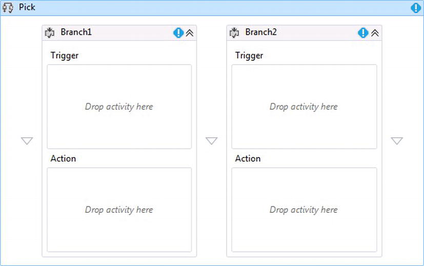
Figure 5-38. Pick activity with two Branch activities
Pick Branches execute in parallel. As one Branch completes, the other branch’s execution is canceled. Bookmarks are added within the Trigger part of a Branch within the Pick activity, and because the Branches fire off in parallel, additional logic can be set up within the other Branch for doing some type of logic. Most implementations take advantage of a Delay activity within the other Branch for giving a time limit for how long a bookmark should wait before the workflow continues execution.
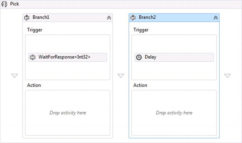
Figure 5-39. Pick activity with a bookmark and a delay activity
Figure 5-39 represents a standard implementation for establishing resuming a workflow from a hosting application. In this case, the Duration property is given to the Delay activity. A simple example would be 00:00:05, which would represent 5 seconds, or TimeSpan.FromSeconds(5), which would represent the same.
CALCULATING THE TAX ON AN ODER IN A TAXABLE STATE
The scenario will pick up from the previous exercise and will demonstrate how to calculate the tax on an order from taxable states. The order will need to be approved if it is over $18.75; If the order is less than $18.75, it will be approved. There will be a time limit of 7 seconds to approve an order; if the order is not approved by then, it will not be approved. You might lose some sells here so hopefully most orders are approved or rejected within the seven seconds.
This exercise will build a composite activity that will be used within a new flowchart workflow. After the logic has been added to calculate state tax, the workflow will approve orders by implementing a bookmark within a Pick activity. A Delay activity will be used to wait for the bookmark to be triggered from the hosting client application; after the set time has expired, the workflow will continue its execution.
- Open Visual Studio 12 and open up the solution containing the project from Exercise 1.
- Right-click the solution, select Add and then New Project. Select the Workflow template.
- Select a new Activity Library and name it Chapter5 .Exercise2.
- Rename the Activity1.xaml that is included with the project to wfCommunication.xaml.
- Double-click the wfCommunication.xaml file to view the workflow designer. Next, drag a Flowchart activity from the toolbox onto the designer canvas. While the workflow has focus and the Properties window is visible, check the ValidateUnconnectedNodes so all activity connections are validated.
- Drag and drop the custom code activity GetCustomerOrders onto the designer canvas. The GetCustomerorders activity was built within Exercise 1 and since it is a compiled activity, it can be seen within the activity toolbox under Exercise 1.
- Add a reference for the Exercise2 project to the Chapter5.DataModel.
- This workflow will return a complex Customers object as a WF OutArgument, so create one by clicking the Arguments tab. Set the Name to argOutCustomers, the Direction to Out and the ArgumentType to Chapter5.DataModel.Customers.
Click the GetCustomersOrders activity so its Property window is viewable and set the OutArgument called outCustomers to the workflow’s OutArgument,argOutCustomers. - Right-click the project and create a new folder called Activities.
- Right-click the new folder and add a new activity from the Workflow template. Rename the activity to CalculateOrder.xaml.
- Click to expand the project Exercise1 and click on workflow wfCustomerOrders.xaml. Right-click the ForEach <Customer> activity and select Copy.
- Go back to the Exercise2 project and click on the activity CalculateOrder.xaml. Right-click and paste in the ForEach <Customer> activity.
- Create a new InArgument for the activity by selecting the Arguments tab. Set the Name property to argInCustomers, and the Direction property to In. Set the Argument type property to Chapter5.DataModel.Customers.
- Click on the Variables tab and remove the variable varCustomers.
- Open the Chapter5.DataModel project and open up the Order.cs file. Add the following lines of code:
[NotMapped]
 Public decimal Tax { get; set; ]

 [NotMapped]
 Public decimal TotalPrice { get; set; ]

 [Required]
Public string ShippingState { get; set; ] - Open up the Activities folder in Exercise2 and click the parent Foreach <T>. Click the ellipses button to change the Values property from from c in varCustomers select c to argInCalcCustomers.
- Click on the Assign activity within the ForEach <OrderLineItem> activity and change the To property to order.TotalPrice and the Value property to order.TotalPrice + lineItem.Price.Value.
- Click on the Variables tab and remove the variable varTotalPrice.
- Remove the WriteLine activity and drag a Flowchart activity from the toolbox and add it where the WriteLine was located.
- Right-click the new Flowchart activity and select Annotations and Add Annotations.Set the annotation to Calculates State tax based on the name of the State passed in (see Figure 5-40).
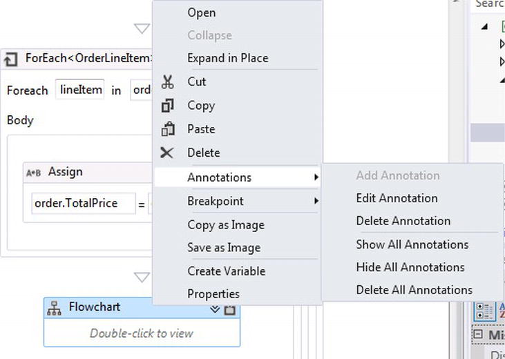
Figure 5-40. Adding an annotation
- Right-click again on the activity and select Annotations and then Show All Annotations.
- Double-click the new Flowchart activity just added. Drag a FlowSwitch from the toolbox onto the designer canvas and set the type to String.
- Make sure the Property window is open while the FlowSwitch activity has focus and set the Expression property to order.ShippingState.
- Right-click the new FlowSwitch activity and select Annotations and Add Annotations. Set the annotation to Tax is determined from an order's ShippingState property.
- Drag a new Assign activity to the designer canvas. Set the To property to order.TotalPrice and the Value property to order.TotalPrice + order.Tax.
- Right-click the new Assign activity and select Annotations and Add Annotations. Set the annotation to Calculates tax based on the State.
- Drag a new Assign activity to the designer canvas. Set the To property to order.Tax and the Value property to order.TotalPrice * .05m.
- Select the Assign activity that was just added and press Ctrl-C to copy the activity. Then press Ctrl-V twice to paste two new Assign activities.
- Click one of the new Assign activities that were pasted and change the Value property of .05m to .03m.
- Right-click the Assign activity where its Value property was changed to reflect the .03m change and select Annotations and Add Annotations. Set the annotation to Georgia is taxed at 3%.
- Click the other Assign activity that was pasted and change the Value property of .05m to .07m.
- Right-click on the on the Assign activity where its Value property was changed to reflect the .07m change and select Annotations and Add Annotations. Set the annotation to Florida is taxed at 7%.
- Right-click on the on the Assign activity that does not have an annotation and select Annotations and Add Annotations. Set the annotation to Alabama is taxed at 5%.
At this point the Flowchart workflow should look something like Figure 5-34, which will provide the functionality for calculating State tax as a composite activity. The next couple of steps set up the approval process. If the annotations are not visible, right click on the workflow and select Annotations and then Show All Annotations. - The WaitForResponse code activity that has been used in other chapters can be used as the bookmark. If you don’t have the bookmark code activity handy, right click on the Activities folder within Exercise2 and add a new class. Rename the class to WaitForResponse
- Paste in the following code within the new class that was added:
using System;
 using System.Collections.Generic;
 using System.Linq;
 using System.Text;
 using System.Activities;
 namespace FlowFocus.WF.Activities
 {
     public sealed class WaitForResponse <TResult> : NativeActivity <TResult>
     {
         public WaitForResponse()
             : base()
     {
         }
         public string ResponseName { get; set; }
         protected override bool CanInduceIdle
         { //override when the custom activity is allowed to make he workflow go idle
             get
             {
                 return true;
             }
         }
         protected override void Execute(NativeActivityContext context)
         {
             context.CreateBookmark(this.ResponseName, new BookmarkCallback(this.ReceivedResponse));
         }
         void ReceivedResponse(NativeActivityContext context, Bookmark bookmark, object obj)
         {
             this.Result.Set(context, (TResult)obj);
         }
     }
} - Right click on the Exercise2 project and select Build. This will compile the new WaitForResponse code activity so it can be selected from the toolbox and added to the workflow.
- After the project compiles, drag an If activity from the toolbox and lightly brush the Assign activity which has the annotation :Calculates tax based on the State , until the nodes show and the two activities are connected.
- Right-click the If activity and select Annotations and Add Annotations. Set the annotation to Orders over $18.75 need approval.
- Double-click the If activity to view its implementation.
- Set the Condition for the If activity to order.TotalPrice> 18.75.
- Drag a Pick activity onto the designer canvas and place it within the Then section of the If activity. The Pick activity will be used to manually approve or reject an order.
- By default, two Branch activities are provided for implementing the Pick activity. Drag the WaitForResponse activity from the Exercise2 section of the toolbox and place it within the Trigger for Branch1. Select its type to Boolean. See Figure 5-41.
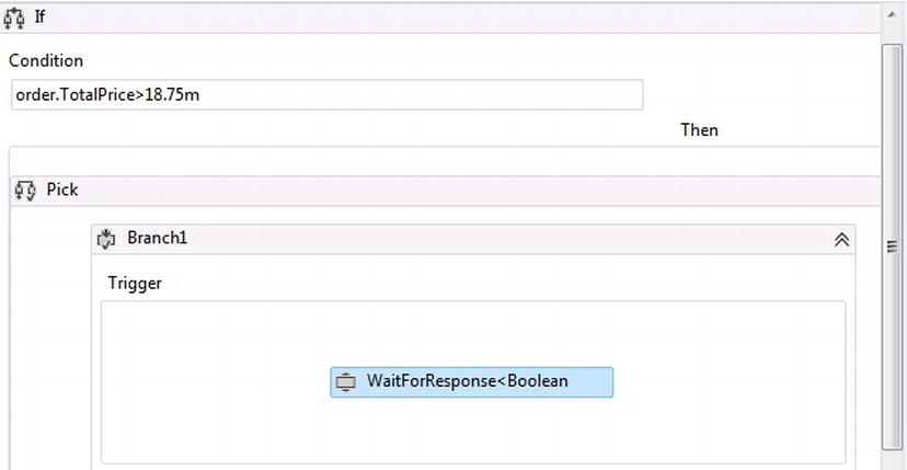
Figure 5-41. Adding a bookmark activity within the trigger
- Drag a Delay activity from the toolbox and place it within the Trigger for Branch2. Click on the Delay activity and set the Duration property to 00:00:07 or seven seconds. The duration of seven seconds can also be set as TimeSpan.FromSeconds(7).
- Drag an Assign activity from the toolbox and place it within the Action for Branch2. Set the To property to order.OrderApproved. Set the Value property to false. The logic that Branch2 now implements is waiting seven seconds for an order to be processed that is over $18.75. If the order is not manually approved after seven seconds, the workflow automatically rejects the order.
- Drag an Assign activity from the toolbox and place it within the Else section of the If activity. Set the To property to order.OrderApproved. Set the Value property to true. The Else part of the If activity will execute if an order is less than $18.75, therefore the order automatically is approved. See Figure 5-42.
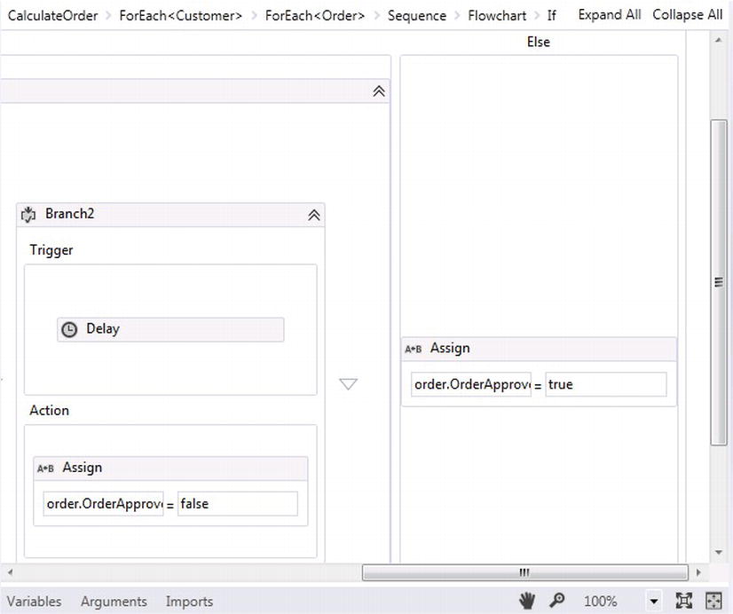
Figure 5-42. Implementing the Else and Branch2
- Click Branch1 and add a WF variable called varApproved. This variable will be used to hold the approval or rejection Boolean response, sent from the hosting application through the WaitForResponse activity. Set the variable type to Boolean and the scope to Branch1 along with a default value of false. This will prevent any orders being automatically approved.
- Drag an If activity into the Action for Branch1. Set the Condition to varApproved.
- Drag an Assign activity from the toolbox and place it within the Then section for the If activity. Set the To property to order.OrderApproved. Set the Value property to true.
- Drag another Assign activity from the toolbox and place it within the Else section for the If activity. Set the To property to order.OrderApproved. Set the Value property to false. See Figures 5-43 and 5-44.
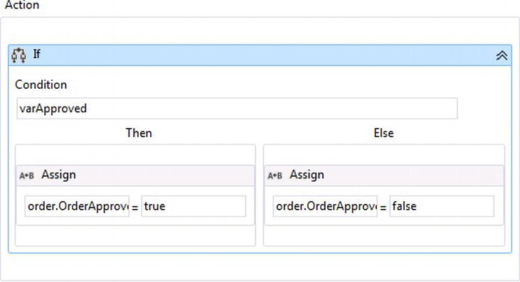
Figure 5-43. Setting the approval flag
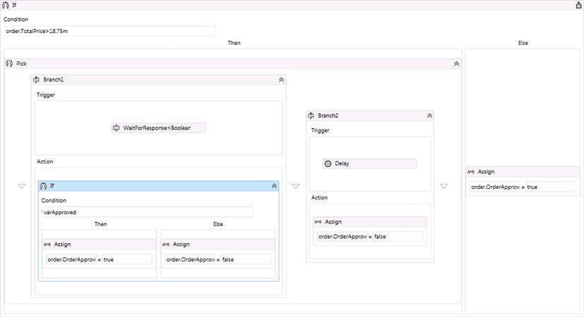
Figure 5-44. Order approval workflow
- Right-click the Exercise2 project and select Build.CalculateOrder activity should now appear within the toolbox. Open the wfCommunication.xaml workflow so the designer is open. Drag and drop the CalculateOrder activity on the designer canvas. Attach the GetCustomerOrders activity to the new CalculateOrder activity; see Figure 5-45.
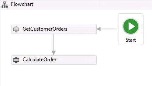
Figure 5-45. wfCommunication parent workflow
At this point the workflow is complete. The next step is to set up the hosting application to start off the workflow and provide functionality for approving or rejecting an order. - Right-click the Chapter5.FlowChart solution, select Add, and then New Project. Select the Windows template and add a new WPF Application. Name the project WFHost.
- Add two references for Exercise1 and Chapter5.DataModel to the WFHost project.
- Click on the MainWindow.xaml file and paste in the following XAML:
<Window
        xmlns = "http://schemas.microsoft.com/winfx/2006/xaml/presentation"
        xmlns:x = "http://schemas.microsoft.com/winfx/2006/xaml"
        xmlns:d = "http://schemas.microsoft.com/expression/blend/2008"
xmlns:mc = "http://schemas.openxmlformats.org/markup-compatibility/2006" mc:Ignorable = "d"
x:Class = "wpfHost.MainWindow"
        Title = "MainWindow" Height = "350" Width = "300">
    <Grid>
        <Grid.RowDefinitions>
            <RowDefinition Height = "158*"/>
            <RowDefinition Height = "8*"/>
            <RowDefinition Height = "146*"/>
        </Grid.RowDefinitions>
        <Button Name = "cmdRuntime" Content = "Get Orders" HorizontalAlignment = "Left"
Margin = "108,83,0,0" VerticalAlignment = "Top" Width = "75" Click = "cmdRuntime_Click" Height = "22"/>
        <Button Name = "cmdApprove" Content = "Approve/DisApprove Order"
HorizontalAlignment = "Left" Margin = "62,136,0,0" VerticalAlignment = "Top" Width = "166"
Click = "cmdApprove_Click" Height = "22"/>
        <CheckBox Name = "chkApprove" IsChecked = "true" Content = "Approve"
HorizontalAlignment = "Left" Margin = "108,116,0,0" VerticalAlignment = "Top"/>
    </Grid>
</Window>
This will add a simple interface with two buttons and a checkbox for approving or rejecting orders (see Figure 5-46).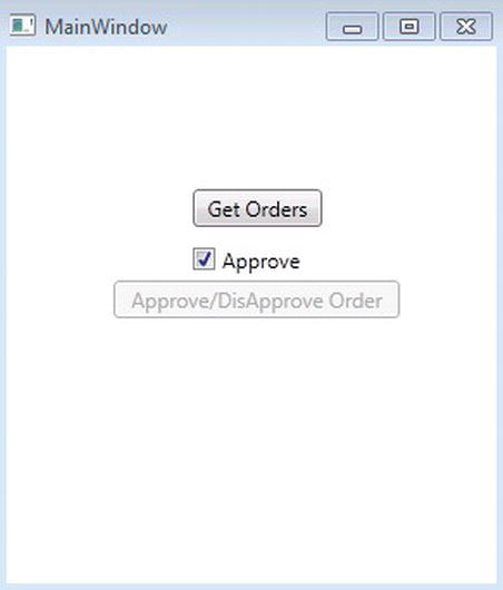
Figure 5-46. Simple approval user interface
- Open up the MainWindow.xaml.cs file and paste in the following code:
using System;
 using System.Activities;
 using System.Collections.Generic;
 using System.Linq;
 using System.Text;
 using System.Threading;
 using System.Threading.Tasks;
 using System.Windows;
 using System.Windows.Controls;
 using System.Windows.Data;
 using System.Windows.Documents;
 using System.Windows.Input;
 using System.Windows.Media;
 using System.Windows.Media.Imaging;
 using System.Windows.Navigation;
 using System.Windows.Shapes;
 using Chapter5 .DataModel;
 using Exercise2;
 namespace wpfHost
 {
     /// <summary>
     /// Interaction logic for MainWindow.xaml
     /// </summary>
     public partial class MainWindow : Window
     {
         private WorkflowApplication wfApp;
         public MainWindow()
         {
             InitializeComponent();
             cmdApprove.IsEnabled =  false;
         }
         private UnhandledExceptionAction OnUnhandledException(WorkflowApplicationUnhandledExceptionEventArgs uh)
         {
             return UnhandledExceptionAction.Terminate;
         }
         /// <summary>
         /// The on workflow completed.
         /// </summary>
         /// <param name = "wc">
         /// The event args
         /// </param>
         private void OnWorkflowIdle(WorkflowApplicationIdleEventArgs iw)
         {
             cmdApprove.IsEnabled =  true;
         }
         /// <summary>
         /// The on workflow completed.
         /// </summary>
         /// <param name = "wc">
         /// The event args
         /// </param>
         private void OnWorkflowCompleted(WorkflowApplicationCompletedEventArgs wc)
         {
             foreach (var arg in wc.Outputs)
             {
                 if (arg.Key.Equals("argOutCustomers"))
                 {
                     var customers =  arg.Value as Customers;
                     foreach (var cust in customers)
                     {
                         foreach (var order in cust.CustomerOrders)
                         {
                             MessageBox.Show(string.Format(" Approved: {2}, Total
Order Price: {0} with Tax: {1}", string.Format("{0:C}", order.TotalPrice),
string.Format("{0:C}", order.Tax),order.OrderApproved.ToString()));
                         }
                     }
                 }
                 cmdRuntime.IsEnabled =  true;
             }
         }
         private void cmdRuntime_Click(object sender, RoutedEventArgs e)
         {
             try
             {
                 Activity workflow =  new wfCommunication();
                 wfApp =  new WorkflowApplication(workflow);
                 wfApp.SynchronizationContext =  SynchronizationContext.Current;
                 wfApp.OnUnhandledException =  OnUnhandledException;
                 wfApp.Completed =  OnWorkflowCompleted;
                 wfApp.Idle =  OnWorkflowIdle;
                 wfApp.Run();
                 cmdRuntime.IsEnabled =  false;
             }
             catch (Exception ex)
             {
                 throw;
             }
         }
         private void cmdApprove_Click(object sender, RoutedEventArgs e)
         {
             try
             {
                 wfApp.ResumeBookmark("ApproveOrder",chkApprove.IsChecked);
                 cmdApprove.IsEnabled =  false;
             }
             catch (Exception ex)
             {
                 throw;
             }
         }
     }
} - Right-click the WFHost project, choose “Set as StartUp Project,” and press F5 to run the solution.
Figure 5-46 represents the default screen used to approve orders through the workflow. Retrieving an order without pressing Approve/Disapprove and waiting seven seconds causes the workflow to respond with the total cost with tax for an order and indicates that the order was not approved through the message box represented in Figure 5-47, as it pops up indicating the total for the order and that the order was not approved.
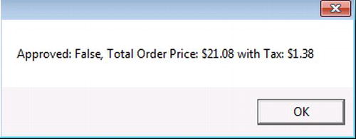
Figure 5-47. Response from the workflow
Clicking “Get Orders” again and clicking on the Approve/Disapprove button once it becomes enabled pops up another message box indicating the same information about the tax and total price, but shows this time that the order has been approved (see Figure 5-48).
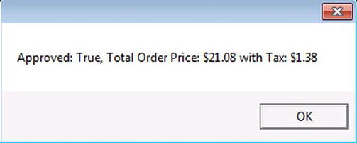
Figure 5-48. Approved order
Summary
Flowchart workflows provide a natural way of modeling processes because they provide a high level of flexibility for flowing logic within business processes. This chapter covered the components for building Flowchart workflows and gave detailed examples for using the Flowchart activity for initiating a flowchart workflow. The FlowDecision activity for controlling the flow for a workflow is based on a Boolean value returned by a condition. The FlowSwitch activity was covered and used to model predetermined values that could be matched for directing the flow of a workflow as well.
The chapter also demonstrated how to use the Microsoft Entity Framework Code First pattern to dynamically change the database tables and data plumbing for accessing dynamic data on the fly. The idea of building composite activities was introduced by using a flowchart control flow where parent activities contained child activities and were then reused as an activity within other workflows. A composite activity was demonstrated for calculating total cost for an order based on each of the order line item costs and state taxes. Finally, the chapter covered communication to flowchart workflows by demonstrating an order approval process. Bookmarks were used with a Pick activity and branches within the Pick activity were used for triggering bookmarks and providing a time limit for how long a bookmark should wait before a workflow should resume.
Now that I have introduced state machine and flowchart control flows, the next chapter will go into detail about building the different types of custom activities and when they should be built and used within workflows for encapsulating domain specific business logic.