
Introduction by Matthew Beckler
Welcome to 10 LED Projects for Geeks, featuring 10 projects of varying complexity that you can build using electronics. You’ll be using the Raspberry Pi and Arduino to create all kinds of gadgets and inventions in this book. In this introduction you’ll learn how to get started with both boards, including installing the necessary software, and you’ll meet the simple electronic component that is the focus of this book: the LED.
At the end of this introduction, you’ll also find a list of popular suppliers for parts you’ll need in the projects.
ALL ABOUT LEDS
Before you start building cool projects using LEDs, let’s take a moment to define them. An LED is a circuit component that converts electricity into light. LEDs come in all colors, shapes, and sizes, and are useful in a variety of projects. Most LEDs are used for indication, meaning they indicate the status of something to a nearby human, such as “door is open,” “radio is on,” or “security system is armed.” Nowadays, larger and brighter LEDs are available that can provide illumination of an object or region. Figure 1 shows some basic LEDs used for indication.

FIGURE 1: A variety of single LEDs
LED stands for light-emitting diode. There are a few words here to unpack, but let’s start with the word diode. In a circuit, a diode works like a one-way valve, permitting electricity to flow in only one predefined direction. If you try to send electricity in the other direction, it won’t flow. Diodes convert alternating current (AC) electricity into direct current (DC), a process called rectification. Diodes were originally designed for use in AM radio receivers to rectify radio frequency signals, but are now used in many different applications where electrical current must flow in only one direction. For example, diodes in many consumer electronics help protect the circuitry against batteries inserted backward. Most of the time, however, the diode aspect of an LED is not important. The rest of the name, light-emitting, simply means that this type of diode is designed to light up when electricity passes through.
How LEDs Work
An LED is a semiconductor device, built with crystalline metals like silicon and germanium, plus small amounts of impurities that change the characteristics of the material. These impurities are added to the semiconductor in a process called doping. The added element, called the dopant, changes the base material into either a p-type or n-type semiconductor.
The distinction between p-type and n-type depends on whether the dopant adds excess free electrons, or causes a deficit of free electrons. The place where these two types of doped semiconductor meet is called the P-N junction, and this is where light is created. Electrical energy passing through the junction excites some of the charge carriers, which emit light when they return to their nonexcited state in a process called electroluminescence.
The exact chemical composition of the semiconductor material determines the band gap of the materials involved, which in turn determines the color of light produced. The first LEDs, developed in the 1960s, emitted light in the infrared end of the color spectrum, which is invisible to the human eye but still useful for scientific experiments. Later developments of other semiconductors and dopants introduced new, visible colors, resulting in mass production of red LEDs in the late 1960s and yellow LEDs in the early 1970s.
A high-brightness blue LED was very difficult to develop, and was considered the Holy Grail of the LED world until 1994, when three Japanese scientists finally figured out the secret to a blue LED. They received the 2014 Nobel Prize in physics for this accomplishment!
LED Configurations
LEDs are very popular for all types of artificial light, and come in many configurations. Let’s explore some of the most common types you’ll encounter.
Single and Bicolor LEDs
The basic single LED configuration has two connections: the anode and cathode. If sufficient voltage is applied, the LED lights up. Pretty simple! Single LEDs come in all different shapes, sizes, and colors, and some, such as the second and fourth ones shown in Figure 1, have extra plastic to help direct the generated light through an opening in the side of an electronics case.
A bicolor LED contains two LEDs in the same two-lead package, typically with the individual LEDs connected anode-to-cathode, as shown in Figure 2.

FIGURE 2: A bicolor LED has two LEDs connected anode-to-cathode.
Usually the two LEDs have different colors, enabling the circuit to display two different colors using only two leads. For example, if current travels through the circuit from left to right, the lower LED turns on. If current travels through the circuit from right to left, the upper LED turns on.
Another fun type is the candle flicker LED, which contains a small computer chip that turns the LED on and off in a flickering pattern, designed to emulate the natural flicker of a candle. You’ve probably seen these LEDs at fancy restaurants or wedding receptions, or anywhere you want to have the ambiance of a candle without the risk of fire.
Red-Green-Blue LED
The red-green-blue (RGB) LED packages three LEDs into one, and actually allows you to create a whole spectrum of colors, not just red, green, and blue. For example, you can combine red and green light to make yellow, green and blue light to create cyan, and red and blue light to make violet. Mixing all three colors of light at the same intensity produces white light.
By combining these three colors of light at varying levels of brightness for each individual color, you can make millions of colors; this is the same method your TV and phone use to display full-color images. Usually, to vary the brightness, each color is switched on and off very rapidly, which tricks our eyes into seeing each color at a different level of intensity. The simplest RGB LED has four connections, one for each of the three colors plus one connection common to all three LEDs. This common connection can be either a common anode (CA) or common cathode (CC), which describes the internal connections of a four-pin RGB LED. Figure 3 shows a diagram of the connections of a common anode RGB LED.
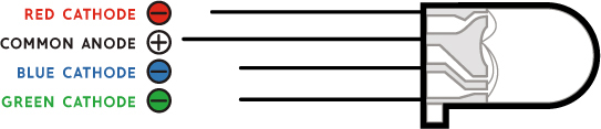
FIGURE 3: A common anode RGB LED contains red, green, and blue LEDs and has four wire leads
Another common type of RGB LED is the digitally controlled RGB LED, which contains a tiny computer chip used to control the brightness of each color. Your microcontroller communicates with the chip in each RGB LED and sets the desired color. The chips in the RGB LEDs are often either the WS2812B or the SK6812, and software libraries exist for almost any system you want to use with them (including Arduino, Raspberry Pi, and many others).
The biggest benefit of using digitally controlled RGB LEDs is that you can “set and forget” them, so your microcontroller can update the LED with the latest desired color, then move on to other tasks instead of having to constantly update the LED brightness. You can also chain RGB LEDs together to form large strings or arrays of full-color RGB LEDs, making them useful for art projects and outdoor displays.
These LEDs are available in a variety of form factors, as shown in Figures 4 and 5.

FIGURE 4: A variety of RGB LEDs: tiny surface-mount chips; four-pin through-hole package; LEDs preattached to small circuit boards

FIGURE 5: A flexible grid of digitally controlled RGB LEDs
These figures show the digitally controlled RGB LEDs in a variety of packages, including tiny surface-mount chips, four-pin through-hole packages, LEDs attached to little circuit boards, and even LEDs preattached in flexible grids.
A final type of RGB LED is a two-connection, internally controlled LED. These are a good option if you’re looking for really cheap RGB LEDs with only two leads. These LEDs have a small control chip inside, but unlike with the digitally controlled RGB LEDs, you can’t actually control what they do. For example, as soon as you provide power to these LEDs, the internal control chip starts displaying a prerecorded sequence of colors on the RGB LED, usually cycling through each primary and secondary color with a nice color fade between each one.
Reading an LED Datasheet
The manufacturer of any LED usually provides a technical datasheet full of facts and figures. It can seem overwhelming, but don’t worry! For the purposes of this book, you need to know only two important numbers to use the LED safely. Figure 6 shows a typical LED datasheet that you’ll use to find the critical details, which are highlighted here in red.

FIGURE 6: An LED datasheet with forward current and forward voltage highlighted in red
An LED produces light when electrical current flows through it, but too much current can overheat and damage it. Using the forward voltage and the maximum current parameters from the datasheet, we can figure out what size resistor we need to operate the LED safely.
Forward Voltage
The forward voltage, or Vf, of an LED is the minimum amount of voltage the LED needs to start conducting electricity. It measures the difference in voltage between the anode and cathode when it’s on. If you apply a voltage below Vf, the LED will not conduct any electricity or light up. When the LED is operating normally, the voltage across the LED will be equal to Vf. We’ll use this fact later on when we start calculating circuit parameters.
The Vf of an LED depends on the chemistry of the materials used, which also determines the color of the LED. For example, red LEDs have a typical Vf of 1.5 to 2 V, while blue or white LEDs tend to have higher Vf values in the range of 2 to 3 V.
Maximum Current
If your voltage exceeds Vf, the LED conducts as much electricity as possible, which can overheat and damage it. To prevent this, we need a second value from the datasheet: the maximum current, which is the maximum electrical current that can pass through the LED without overheating it.
Most LEDs have a maximum steady current and a higher maximum pulsed current. Usually, we use the maximum steady current for our calculations. We measure current in units of amperes, or amps (abbreviated as A), and in thousandths of an amp, or milliamps (abbreviated as mA). Current is the amount of electricity that is flowing through a device, and it determines the brightness of an LED. For example, most small LEDs light up with only 10 to 30 mA of current. Some larger LEDs and LED assemblies need hundreds of milliamps or even several amps of current!
Resistance, LEDs, and Ohm’s Law
To safely power an LED, we need to provide at least Vf voltage across the LED but also limit the current to ensure it remains below the datasheet’s max current allowed. The easiest way to do this is to add a resistor “in series” (inline) with the LED. A resistor is the simplest possible circuit component, with a very simple relationship between the amount of voltage across the resistor, the current flowing through the resistor, and the amount of resistance of the resistor. This relationship is called Ohm’s law and can be expressed by the following equation:
voltage = current × resistance
We can simplify this expression using the letter I to represent current, giving us the familiar V = I × R equation for Ohm’s law. Resistance is measured in units called ohms, abbreviated as Ω.
Let’s use a practical example to understand this relationship. Imagine a resistor that has 1,000 Ω of resistance. If we apply 12 V to this resistor, how much current will flow through it? To answer this question, we simply substitute the variables in the equation with the information given:

Using Ohm’s law, you can see that 12 mA of current will flow through a resistor with 1,000 Ω of resistance when we apply 12 V. Let’s try this same calculation again, but with 36 V this time:

Now, let’s see how resistors can help us protect an LED from drawing too much current.
Calculating Resistance to Use with an LED
If we pair an LED with a resistor, they work together to limit the current through both devices. Figure 7 shows how this works.

FIGURE 7: Using a resistor in series (inline) with an LED to limit the current and protect the LED
Notice that the current through the LED is the same as the current through the resistor. You can see that the overall power supply voltage is also equal to the voltage across the LED plus the voltage across the resistor. We can write these two facts as two simple equations to describe our circuit:

We already know that the LED current needs to be below the maximum it can handle. For this circuit, let’s say we want 20 mA of LED current maximum. We also know the LED’s forward voltage (Vf) from the datasheet. For this example, let’s say the forward voltage is 2 V, and the power supply voltage is 5 V. With these facts, we can fill in some variables in the two equations.
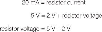
So we have computed that the resistor current is 20 mA, and the resistor voltage is 3 V. All we need to do now is to calculate what resistance value we need for the resistor, using Ohm’s law.

Rearranging, we find:

This tells us we need 150 Ω of resistance to keep the LED current at 20 mA with a 5 V power supply. Keep in mind that most resistors are accurate only to within 5 percent of their specified value. This means that a 1,000 Ω resistor value will have an actual resistance between 950 and 1,050 Ω, and some resistors might even have a 10 percent tolerance for the accuracy of their value. If your calculations result in a resistance value that isn’t commonly available, round up to the nearest available value. Rounding up the resistance may slightly reduce the current, but it’s better than slightly increasing the current and possibly overloading the LED!
We can generalize this calculation for a situation where you have an LED with inline resistor connected to a power supply:

That’s a lot of math. But how does this technology get used? Let’s look at some of the ways people use LEDs.
LEDs in the World
We use LEDs in a wide variety of applications in both obvious and not-so-obvious ways. For example, many digital clock displays on appliances like the microwave or radio have a seven-segment display for each digit of the time. This display consists of seven LEDs arranged in the shape of a blocky numeral 8, as shown in Figure 8. By turning each of the seven segments on or off, we can display all the digits from 0 through 9.

FIGURE 8: A seven-segment display consists of multiple LEDs integrated into a single plastic package, enabling the display of digits 0 through 9.
A less obvious LED application is their use in many fiber optic cables and infrared remote controls for communications. The vast undersea internet cables that connect cities and continents consist of thin glass strands with an LED (or sometimes a laser) at each end, transmitting pulses of light through the cable to communicate data. Figure 9 shows an example of fiber optic cables.

FIGURE 9: A bundle of fiber optic cables
Infrared (IR) remote controls for televisions and other appliances use a special type of LED that creates invisible infrared light that only the appliance’s sensor can detect. Because many video cameras are sensitive to infrared light, we use IR LEDs in security cameras to generate nighttime illumination that remains invisible to human eyes.
Many new traffic signals and automobile lights now use LEDs, as shown in Figure 10, which helps to increase visibility and reduce both power consumption and waste heat generation.

FIGURE 10: An LED traffic light
With the relatively recent development of pleasing “warm white” LEDs, shown in Figure 11, many households and businesses are starting to adopt LED lighting. These LED bulbs can be over 10 times more efficient than an incandescent light bulb, and their reduced energy use makes up for their higher purchase price within just a few years of use.

FIGURE 11: A white LED light bulb designed to fit in a standard lamp socket
Now that you’ve learned about the different types of LED and how they work, you’re almost ready to dive in to the projects! In addition to a wide variety of LEDs, some of the projects in this book will need a Raspberry Pi or Arduino. These next sections guide you through setting up both. If you already have these set up, or want to set them up later when you need them, you can skip these sections for now and go straight to the first project!
GETTING STARTED WITH THE RASPBERRY PI
This section will show you how to set up your Raspberry Pi with a formatted SD card and the Raspbian operating system.
What You’ll Need
Raspberry Pi is perhaps the most well known of the small-form-factor computers on the market right now. About the size of a credit card, the Raspberry Pi is a tiny computer that includes a processor, USB and other connectors, and input/output pins, as shown in Figure 12.
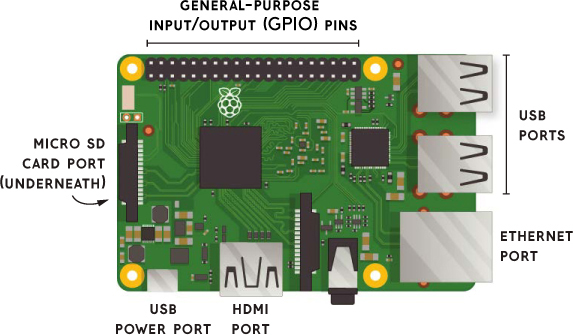
FIGURE 12: A Raspberry Pi single-board computer
There are a few different models of Pi. Any Pi will do for the purposes of this book.
Like any computer, the Pi needs a keyboard, mouse, display, power supply, and some storage for the operating system. You can use any USB mouse and keyboard as well as any HDMI display, like a computer monitor or a TV. The power supply is a micro USB connector like you’ll find in many cell phones, so you can reuse an old phone charger if you already have one. While many computers have a spinning magnetic hard disk drive for storage, the Pi needs a separate micro SD card to store the operating system (OS) and files you create. You’ll therefore need to get an 8GB or 16GB micro SD card—the bigger, the better. We’ll be following along with the official Raspberry Pi Software Guide (https://www.raspberrypi.org/learning/software-guide/quickstart/).
Installing Raspbian with NOOBS
The most popular OS for Raspberry Pi is called Raspbian, and you can easily install it by copying files onto the micro SD card from another computer. The easiest way to get started with Raspberry Pi is by using the NOOBS (“New Out-of-the-Box Software”) system, which lets you choose which OS to install.
To install NOOBS, visit the Raspberry Pi website’s Downloads section (https://www.raspberrypi.org/downloads/noobs/). Then select the NOOBS (Offline and network install) option. Don’t select NOOBS LITE, which doesn’t have Raspbian included by default. To download NOOBS, click the Download ZIP option. You can select Download Torrent instead if you’re comfortable using BitTorrent software (this helps reduce bandwidth costs for the Raspberry Pi Foundation). Either way, when the download finishes, open the ZIP archive using your unzip program and extract the files to your computer. Put them somewhere easy to find, like on your Desktop or in your Documents directory.
Preparing the SD Card
Next, we need to format the micro SD card to prepare it to receive the NOOBS files. Even if your SD card is brand new, I recommend formatting it, as it needs to be entirely empty to receive the OS. If your computer runs Windows or macOS, download SD Formatter 4.0 from the SD Association website (https://www.sdcard.org/) by going to the Downloads section and finding the formatter for your current OS. Follow the instructions to install the software and use it to format your micro SD card.
NOTE
If your computer runs Linux, you can use any disk formatting utility to format the SD card using a Master Boot Record (MBR) and a single FAT partition.
After formatting the micro SD card, drag and drop the extracted NOOBS files onto the micro SD card drive. Wait until the files finish copying, then safely remove the micro SD card and insert it into the Raspberry Pi.
Starting Up Your Pi
If you haven’t already, plug in your keyboard and mouse. Connect to your display with the HDMI cable. If you have an Ethernet cable available to connect your Pi to the internet, plug it in at this time. Finally, plug in the micro USB power cable, and the Raspberry Pi should start up. Unlike most computers, the Raspberry Pi doesn’t have a power button, but automatically powers up when you plug in the power connector. Refer to Figure 12 to see which ports are which.
If this is the first time you’re using this micro SD card, the NOOBS system will ask you to select which operating system you want to use. Because it’s designed especially for the Raspberry Pi and built in to the NOOBS system, Raspbian is the OS I recommend, but there are other options that may require an internet connection to download.
Now that you’re done setting up your Raspberry Pi is and the Raspbian OS, you’re ready to build a bunch of projects. Project 6 in this book uses the Pi. After that, there are a ton of cool projects documented online you can try, both on the official Raspberry Pi website (https://www.raspberrypi.org/resources/) and on other websites like Instructables and Hack-a-Day.
GETTING STARTED WITH THE ARDUINO AND THE ARDUINO IDE
Some projects in this book use the Arduino as their brains. The Arduino is less complicated than the Raspberry Pi in that it doesn’t have the computer and networking capabilities that the Pi has, but simply runs one program over and over until you unplug it. However, the Arduino excels at many hardware projects, especially when high-precision timing is required (such as talking to digital RGB LEDs). Let’s explore what Arduino is, cover how to install it, and get familiar with the Arduino workflow.
What Is Arduino?
The Arduino project began in 2003 with the aim of making it easy for people to get started with electronics, programming, and interactive design. The project created a variety of open source microcontroller circuit boards, along with a series of software libraries tied together in an easy-to-use integrated development environment (IDE). Arduino boards provide an interface between the digital world and the real world, giving users a simple way to read data from sensors like buttons, switches, and thermometers, as well as drive actuators such as lights, motors, and LED displays. An entire ecosystem has sprung up around the core Arduino system, offering a huge set of add-on hardware and software you can use to design the next great robot, art installation, or musical instrument.
The basic Arduino workflow goes something like this. First, write the programming code, called a sketch, in the Arduino IDE program on your computer. Second, connect the Arduino circuit board to your computer using a USB cable. Third, select the Upload button in the Arduino IDE to transfer the code into the Arduino board. The code will then automatically start running, reading sensors and driving actuators to interact with the real world.
The most popular Arduino board is the Arduino Uno, which we’ll use as an example in this section to illustrate the process of uploading code into the board. Arduino boards have a main processor chip (such as the Atmel ATMega328 on the Arduino Uno) as well as a USB chip that handles the interface between the computer and the main processor. These boards can be connected to your computer with just a USB cable.
Other Arduino-compatible boards, such as the EMSL Diavolino and the SparkFun Arduino Pro Mini, don’t include the USB chip, usually to reduce cost. For these boards, you need a separate piece of hardware to provide the USB interface between the computer and the main processor chip. Because the most popular USB interface chip for the Arduino is made by a company called FTDI, we call this USB interface an FTDI cable, or an FTDI Friend.
Installing and Using the Arduino IDE
To get started with Arduino, you first need to install the Arduino IDE from the official website (https://www.arduino.cc/) under the Software section. I recommend you download the offline IDE rather than relying on the web editor. Packages are available for Windows, macOS, and Linux distributions, including Raspberry Pi.
Figure 13 shows the Arduino IDE running on Windows 10.

FIGURE 13: The Arduino IDE interface
The interface should look similar across different platforms. The important toolbar buttons are as follows:
➊ checkmark Checks for any errors and verifies that the sketch can be compiled
➋ right arrow Uploads and transfers the sketch into the circuit board
➌ magnifying glass Opens the serial monitor to see information sent by the Arduino board
The programming code for the sketch goes into the large text area in the center of the screen. The programming language used for Arduino is called Wiring, which is similar to the C++ language.
What an Arduino Sketch Looks Like
The Arduino IDE comes with a large number of example sketches, intended to demonstrate all the different things that an Arduino can do. The simplest sketch, called Blink, blinks an LED light. Most Arduino boards have a built-in LED that you can turn on and off using the sketch code, and the Blink sketch uses this built-in LED as an output signal. This sketch is a great way to test out a new Arduino board and confirm that the IDE is properly set up.
To open the Blink example sketch, use the menus to select File ▸ Examples ▸ 01.Basics ▸ Blink, as shown in Figure 14.

FIGURE 14: Selecting and opening the Blink sketch
Every Arduino sketch has at least two sections of programming code, which we call functions. The first required function is setup(), which we call only once when the board is first powered up or reset. The setup() function is where we place all activity having to do with initialization and configuration, such as initializing the functionality of each pin and configuring the features of an external library. The other required function is loop(), which is called repeatedly after setup() has been called once. You can create your own functions, too, to help organize your sketch code. Listing 1 shows the complete program listing for the Blink sketch.
LISTING 1: The complete code listing for the Blink sketch
// the setup function runs once when you press reset
// or power the board
void setup() {
// initialize digital pin LED_BUILTIN as an output
pinMode(LED_BUILTIN, OUTPUT);
}
// the loop function runs over and over again forever
void loop() {
digitalWrite(LED_BUILTIN, HIGH); // turn the LED on (HIGH
// is the voltage level)
delay(1000); // wait for a second
digitalWrite(LED_BUILTIN, LOW); // turn the LED off by
// making the voltage LOW
delay(1000); // wait for a second
}
Here, you can see that the setup() function configures the LED’s pin as an output pin that can turn the LED either on or off. This is in contrast to an input pin, which would read in a HIGH, LOW, or even a varying voltage applied to it.
NOTE
Lines and phrases beginning with // are comments and do not affect the code’s execution.
The loop() function contains two other Arduino functions. The simplest is delay(), which pauses the program execution for the specified number of milliseconds (thousandths of a second). Each time the program reaches the delay(1000) line, it stops and waits for 1 second before continuing.
The digitalWrite() function works only on a previously configured output pin, and it sets the output voltage to either HIGH or LOW. The LOW voltage is always 0 V (usually called ground), and the HIGH voltage depends on the specific circuit board, but is usually 5 V or 3.3 V.
In sum, this sketch first configures the LED’s pin as a digital output, and then turns the LED on, waits for 1 second, turns the LED off, waits 1 second, and repeats the process over and over again until the Arduino board is reset or the power is disconnected.
Configuring Your Board and Port
Before we compile and upload the sketch into the Arduino board, we need to use the Tools menu to tell the Arduino IDE what kind of Arduino board we’re using. Figure 15 shows how you can select the Arduino Uno by choosing Tools ▸ Board. Here, we’re using the Uno as an example, but be sure to select the entry that matches the board you’re using.

FIGURE 15: Using the Tools menu to select which Arduino board is connected
Some Arduino boards have additional options you can use to specify the amount of available memory, how fast it should run, or which processor type is installed, but the Uno doesn’t have any options like this. All boards do have the Port option, which specifies which USB port the device is connected to. This is platform dependent, of course, because ports have different names on macOS, Windows, and Linux, but most modern Arduino boards will be able to transmit their name, which should show up in the Port menu as shown in Figure 16.

FIGURE 16: Selecting the correct Arduino board from the list of connected devices in the Port menu
After you configure the board and port, the final step is to use the Upload button to prepare (compile) and upload the sketch code into the attached Arduino board. To do this, press the right-arrow button on the toolbar, or select the Sketch ▸ Upload menu option. You should be able to see the compiler output in the black area below the sketch code, which also displays how much space remains for program storage and global variables. Because each Arduino board allots different amount of space for storing the compiled sketch and the global variables, be sure to pay attention to these numbers to keep track of how full the chip is getting.
Although the Blink sketch doesn’t transmit any debugging messages to the serial monitor, many other sketches use the serial monitor as a way to provide feedback on the running program. Some sketches even take input from the serial monitor and use it to influence how the program runs. In this way, you can make your sketches interact with the computer or any other device that can talk to a USB serial port.
Now that you’ve learned the basic workflow of using the Arduino IDE to compile and upload code, let’s touch on a couple of add-ons used in this book.
Some of the projects in this book use Arduino add-ons for particular tasks. For example, the Adafruit Trinket is used for Project 2: The Desktop UFO, and the Adafruit Lilypad, which is often used for developing wearables, appears in Project 9: Wearable Timing Bracer. Each project that uses an add-on will explain how to set it up and use it.
As mentioned, some Arduino-compatible boards skip the USB interface chip to save cost or reduce power consumption, or both. One popular board like this is the Arduino Pro Mini, created by SparkFun. The Arduino Pro Mini (shown here; left) requires a separate board, the FTDI Friend (shown here; right) to provide the USB interface with the computer. These two boards work together to provide a low-cost Arduino board with a removable (and reusable) USB interface.

The photos are aligned as the boards would be when connected together. Simply solder in some header pins on the right side of the Arduino Pro Mini so that they can connect to the socket on the FTDI Friend. Use the Arduino IDE’s Boards menu to select Arduino Pro or Pro Mini. This should enable the Processor option just below the Board option; be sure to pick the correct processor type and speed.
RECOMMENDED SUPPLIERS
Throughout this book, each project lists a small number of online stores as a source for the components used in it. Still, every store has products unique to it, so more sources are better! The following are online stores serving worldwide or regional markets.
United States
Adafruit (New York; www.adafruit.com) This electronics store has a ton of LED products and an impressive array of microcontrollers, breakout boards, and kits.
BGMicro (Texas; www.bgmicro.com) We love the unusual and obsolete parts found in this quirky store.
Digi-Key (Minnesota; www.digikey.com) Get lost in the vast array of parts found in this huge online store.
Evil Mad Scientist (California; www.evilmadscientist.com) Kitmakers and component sellers par excellence. Owners Lenore Edman and Windell H. Oskay also cowrote Project 1 of this book.
Jameco Electronics (California; www.jameco.com) Around since 1974, Jameco might literally be your dad’s electronics store. It has a great paper catalog.
Mouser Electronics (Texas; www.mouser.com) If you want a rare sensor or a thousand of a component, check with this mega-distributor.
SparkFun Electronics (Colorado; www.sparkfun.com) Founded by a college student, SparkFun has exploded into an online retailer of kits and individual components.
Tower Hobbies (Illinois; www.towerhobbies.com) Champaign-based Tower Hobbies is a radio-control and drone superstore.
Europe
Elextra (Denmark; www.elextra.dk) This fun store has kits and tools and a wider-than-normal selection of electronic products.
Farnell/Newark element 14 (United Kingdom; www.newark.com) Based out of Leeds, Farnell sells electronic components throughout the world. Chicago-based Newark is its sister company.
Maplin (United Kingdom; www.maplin.co.uk) Electronics retailer Maplin has over 200 stores in the UK and sells online as well.
Play Zone (Switzerland; www.play-zone.ch) This hobby electronics site, available in English and German, has everything from building sets to Raspberry Pis to individual components.
RS Components (UK; https://uk.rs-online.com/web) This electronics superstore boasts half a million products.
Asia
AliExpress (China; www.aliexpress.com) There is no way to enumerate all the crazy things you can buy from eBay-like AliExpress.
DealExtreme (Hong Kong; www.dx.com) Everything imaginable available and at eyebrow-raising prices—what could go wrong?
HobbyKing (Hong Kong; www.hobbyking.com) This is a radio-control and drone superstore with warehouses in the US.
Seeed Studio (Shenzhen; www.seeedstudio.com) Not just an online store, Seeed also runs business incubator Seeed Propogate as well as Seeed Fusion, a prototyping shop.