
An Overview of Architecture-Level Power- and Energy-Efficient Design Techniques
Ivan Ratković*,†; Nikola Bežanić‡; Osman S. Ünsal*; Adrian Cristal*,†,§; Veljko Milutinović‡ * Barcelona Supercomputing Center, Barcelona, Spain
† Polytechnic University of Catalonia, Barcelona, Spain
‡ School of Electrical Engineering, University of Belgrade, Belgrade, Serbia
§ CSIC-IIIA, Barcelona, Spain
Abstract
Power dissipation and energy consumption became the primary design constraint for almost all computer systems in the last 15 years. Both computer architects and circuit designers intent to reduce power and energy (without a performance degradation) at all design levels, as it is currently the main obstacle to continue with further scaling according to Moore's law. The aim of this survey is to provide a comprehensive overview of power- and energy-efficient “state-of-the-art” techniques. We classify techniques by component where they apply to, which is the most natural way from a designer point of view. We further divide the techniques by the component of power/energy they optimize (static or dynamic), covering in that way complete low-power design flow at the architectural level. At the end, we conclude that only a holistic approach that assumes optimizations at all design levels can lead to significant savings.
Abbreviations
A Switching Activity Factor
ABB Adaptive Body Biasing
BHB Block History Buffer
C Capacitance
CMP Chip-Multiprocessor
CPI Cycles per Instruction
CU Control Unit
d Delay
DCG Deterministic Clock Gating
DVFS Dynamic Voltage and Frequency Scaling
DVS Dynamic Voltage Scaling
E Energy
EDP Energy-Delay Product
EiDjP Energyi-Delayj Product
EPI Energy-per-Instruction
FP Floating Point
FU Functional Unit
GALS Globally Asynchronous Locally Synchronous
IQ Instruction Queue
IPC Instructions Per Cycle
LSQ Load/Store Queue
LUT Look-up Table
MCD Multiple-Clock-Domain
MFLOPS Millions of Floating point Operations Per Second
MILP Mixed-Integer Linear Programming
MIPS Millions of Instructions Per Second
NEMS Nanoelectromechanical Systems
P Power
PCPG Per-Core Power Gating
RBB Reverse Body Biasing
RDO Runtime DVFS Optimizer
RF Register File
ROB Reorder Buffer
SIMD Single Instruction, Multiple Data
UC Micro-Operation Cache
1 Introduction
After the technology switch from bipolar to CMOS, in the 1980s and early 1990s, digital processor designers had high performance as the primary design goal. At that time, power and area remained to be secondary goals. Power started to become a growing design concern when, in the mid- to late-1990s, it became obvious that further technology feature size scaling according to Moore's law [1] would lead to a higher power density, which could became extremely difficult or almost impossible to cool.
While, during the 1990s, the main way to reduce microprocessor power dissipation was to reduce dynamic power, by the end of the twentieth century the leakage (static) power became a significant problem. In the mid-2000s, rapidly growing static power in microprocessors approaches to its dynamic power dissipation [2]. The leakage current of a MOSFET increases exponentially with a reduction in the threshold voltage. Static power dissipation, a problem that had gone away with the introduction of CMOS, became a forefront issue again.
Different computer systems have different design goals. In high-performance systems, we care more about power dissipation than energy consumption; however, in mobile systems, the situation is reverse. In battery-operated devices, the time between charges is the most important factor; thus, lowering the microprocessor energy as much as possible, without spoiling performance, is the main design goal. Unfortunately, the evolution of the battery capacity is much slower than the electronics one.
Power density limits have already been spoiling planned speed-ups by Moore's law, and this computation acceleration degradation trend is still growing. As technology feature size scaling goes further and further, power density is getting higher and higher. Therefore, it is likely that, very soon, majority of the chip's area is going to be powered off; thus, we will have “dark silicon.” Dark silicon (the term was coined by ARM) is defined as the fraction of die area that goes unused due to power, parallelism, or other constraints.
Due to the above described facts, power and energy consumption are currently one of the most important issues faced by computer architecture community and have to be reduced at all possible levels. Thus, there is a need to collect all efficient power/energy optimization techniques in a unified, coherent manner.
This comprehensive survey of architectural-level energy- and power-efficient optimization techniques for microprocessor's cores aims to help low-power designer (especially computer architects) to find appropriate techniques in order to optimize their design. In contrast with the other low-power survey papers [3–5], the classification here is done in a way that processor designers could utilize in a straightforward manner—by component (Section 3). The presentation of the techniques (Section 4) was done by putting the emphasis on newer techniques rather than older ones. The metrics of interest for this survey are presented in Section 2 which help reading for audience with less circuit-level background. Future trends are important in the long-term projects as CMOS scaling will reach its end in a few years. Current state of microprocessor scaling and a short insight of novel technologies are presented in Section 5. At the end, in Section 6 we conclude this chapter and a short review of the current low-power problems.
2 Metrics of Interest
Here we present the metrics of interest as a foundation for later sections. We present both circuit- and architectural-level metrics.
2.1 Circuit-Level Metrics
We can define two types of metrics which are used in digital design—basic and derived metrics. The first one is well-known, while the latter is used in order to provide a better insight into the design trade-offs.
2.1.1 Basic Metrics
Delay (d) Propagation delay, or gate delay, is the essential performance metric, and it is defined as the length of time starting from when the input to a logic gate becomes stable and valid, to the time that the output of that logic gate is stable and valid. There are several exact definitions of delay but it usually refers to the time required for the output to reach from 10% to 90% of its final output level when the input changes. For modules with multiple inputs and outputs, we typically define the propagation delay as the worst-case delay over all possible scenarios.
Capacitance (C) is the ability of a body to hold an electrical charge, and its unit according to IS is the Farad (F). Capacitance can also be defined as a measure of the amount of electrical energy stored (or separated) for a given electric potential. For our purpose more appropriate is the last definition.
Switching Activity Factor (A) of a circuit node is the probability the given node will change its state from 1 to 0 or vice versa at a given clock tick. Activity factor is a function of the circuit topology and the activity of the input signals. Knowledge of activity factor is necessary in order to analytically compute—estimate dynamic power dissipation of a circuit and it is sometimes indirectly expressed in the formulas as Cswitched, which is the product of activity factor and load capacitance of a node CL. In some literature, symbol α is used instead of A.
Energy (E) is generally defined as the ability of a physical system to perform a work on other physical systems and its SI unit is the Joule (J). The total energy consumption of a digital circuit can be expressed as the sum of two components: dynamic energy (Edyn) and static energy (Estat).
Dynamic energy has three components which are results of the next three sources: charging/discharging capacitances, short-circuit currents, and glitches. For digital circuits analysis, the most relevant energy is one which is needed to charge a capacitor (transition 0→1), as the other components are parasitic; thus, we cannot affect them significantly with architectural-level low-power techniques. For that reason, in the rest of this chapter, the term dynamic energy is referred to the energy spent on charging/discharging capacitances. According to the general energy definition, dynamic energy in digital circuits can be interpreted as: When a transition in a digital circuit occurs (a node changes its state from 0 to 1 or from 1 to 0), some amount of electrical work is done; thus, some amount of electrical energy is spent. In order to obtain analytical expression of dynamic energy, a network node can be modeled as a capacitor CL which is charged by voltage source VDD through a circuit with resistance R. In this case, the total energy consumed to charge the capacitor CL is:
where the half of the energy is dissipated on R and half is saved in CL,
The total static energy consumption of a digital network is the result of leakage and static currents. Leakage current Ileak consists of drain leakage, junction leakage, and gate leakage current, while static current IDC is DC bias current which is needed by some circuits for their correct work. Static energy at a time moment t(t > 0) is given as follows:

As CMOS technology advances into sub-100 nm, leakage energy is becoming as important as dynamic energy (or even more important).
Power (P) is the rate at which work is performed or energy is converted, and its SI unit is the Watt (W). Average power (which is, for our purpose, more important than instantaneous power) is given with the formula: ![]() , in which ΔE is amount of energy consumed in time period Δt. Power dissipation sources in digital circuits can be divided into two major classes: dynamic and static. The difference between the two is that the former is proportional to the activity in the network and the switching frequency, whereas the latter is independent of both.
, in which ΔE is amount of energy consumed in time period Δt. Power dissipation sources in digital circuits can be divided into two major classes: dynamic and static. The difference between the two is that the former is proportional to the activity in the network and the switching frequency, whereas the latter is independent of both.
Dynamic power dissipation, like dynamic energy consumption, has several sources in digital circuits. The most important one is charging/discharging capacitances in a digital network and it is given as:
in which f is the switching frequency, while A, CL, and VDD were defined before. The other sources are results of short-circuit currents and glitches, and they are not going to be discussed due to the above-mentioned reasons.
Static power in CMOS digital circuits is a result of leakage and static currents (the same sources which cause static energy). Static power formula is given as follows:
Another related metric is surface power density, which is defined as power per unit area and its unit is ![]() . This metric is the crucial one for thermal studies and cooling system selection and design, as it is related with the temperature of the given surface by Stefan–Boltzmann law [6].
. This metric is the crucial one for thermal studies and cooling system selection and design, as it is related with the temperature of the given surface by Stefan–Boltzmann law [6].
2.1.2 Derived Metrics
In today's design environment where both delay and energy play an almost equal role, the basic design metrics may not be sufficient. Hence, some other metrics of potential interest have been defined.
Energy-Delay Product (EDP) Low power often used to be viewed as synonymous with lower performance that, however, in many cases, application runtime is of significant relevance to energy- or power-constrained systems. With the dual goals of low energy and fast runtimes in mind, EDP was proposed as a useful metric [7]. EDP offers equal “weight” to energy and performance degradation. If either energy or delay increases, the EDP will increase. Thus, lower EDP values are desirable.
Energyi-Delayj Product (EiDjP) EDP shows how close the design is to a perfect balance between performance and energy efficiency. Sometimes, achieving that balance may not necessarily be of interest. Therefore, typically one metric is assigned greater weight, for example, energy is minimized for a given maximum delay or delay is minimized for a given maximum energy. In order to achieve that, we need to adjust exponents i and j in EiDjP. In high-performance arena, where performance improvements may matter more than energy savings, we need a metric which has i < j, while in low-power design we need one with i > j.
2.2 Architectural-Level Metrics
![]() Millions of Instructions Per Second (MIPS) per Watt is the most common (and perhaps obvious) metric to characterize the power-performance efficiency of a microprocessor. This metric attempts to quantify efficiency by projecting the performance achieved or gained (measured in MIPS) for every watt of power consumed. Clearly, the higher the number, the “better” the machine is.
Millions of Instructions Per Second (MIPS) per Watt is the most common (and perhaps obvious) metric to characterize the power-performance efficiency of a microprocessor. This metric attempts to quantify efficiency by projecting the performance achieved or gained (measured in MIPS) for every watt of power consumed. Clearly, the higher the number, the “better” the machine is.
![]() While the previous approach seems a reasonable choice for some purposes, there are strong arguments against it in many cases, especially when it comes to characterizing high-end processors. Specifically, a design team may well choose a higher frequency design point (which meets maximum power budget constraints) even if it operates at a much lower
While the previous approach seems a reasonable choice for some purposes, there are strong arguments against it in many cases, especially when it comes to characterizing high-end processors. Specifically, a design team may well choose a higher frequency design point (which meets maximum power budget constraints) even if it operates at a much lower ![]() efficiency compared to one that operates at better efficiency but at a lower performance level. As such,
efficiency compared to one that operates at better efficiency but at a lower performance level. As such, ![]() or even
or even ![]() may be appropriate metric of choice. On the other hand, at the lowest end (low-power case), designers may want to put an even greater weight on the power aspect than the simplest MIPS/Watt metric. That is, they may just be interested in minimizing the power for a given workload run, irrespective of the execution time performance, provided the latter does not exceed some specified upper limit.
may be appropriate metric of choice. On the other hand, at the lowest end (low-power case), designers may want to put an even greater weight on the power aspect than the simplest MIPS/Watt metric. That is, they may just be interested in minimizing the power for a given workload run, irrespective of the execution time performance, provided the latter does not exceed some specified upper limit.
Energy-per-Instruction (EPI) One more way of expressing the relation between performance (expressed in number of instructions) and power/energy.
![]() While aforementioned metrics are used for all computer systems in general, when we consider scientific and supercomputing,
While aforementioned metrics are used for all computer systems in general, when we consider scientific and supercomputing, ![]() is the most common metric for power-performance efficiency, where Millions of Floating point Operations Per Second (MFLOPS) is a metric for floating point performance.
is the most common metric for power-performance efficiency, where Millions of Floating point Operations Per Second (MFLOPS) is a metric for floating point performance.
3 Classification of Selected Architecture-Level Techniques
This section presents a classification of existing examples of architectural-level power and energy-efficient techniques. In the first section, the classification criteria are given. The classification criteria were chosen to reflect the essence of the basic viewpoint of this research. Afterward, the classification tree was obtained by application of the chosen criteria. The leaves of the classification are the classes of examples (techniques). The list of the most relevant examples for each class is given in the second section.
3.1 Criteria
The classification criteria of interest for this research as well as the thereof are given in Table 1. All selected classification criteria are explained in the caption of Table 1 and elaborated as follows:
Table 1
Classification Criteria (C1, C2, C3): Hierarchical Level, Core Block Type, and Type of Power/Energy Being Optimized
| C1: Hierarchical level | - Core |
| - Functional blocks | |
| C2: Core block type | - Front-end |
| - Back-end | |
| C3: Type of power/energy being optimized | - Dynamic |
| - Static |
C1 is a binary criterion (core, functional blocks); C2 is also binary criterion (functional units, control units, and RF); and C3 is, like the previous two criteria, is binary (dynamic, static).
C1 Criterion C1 is the top criterion and divides the techniques by level at which they can be applied, core- or core blocks level. Here, the term “Core” implies processor's core without L1 cache.
C2 This criterion divides core blocks into front- and back-end of the pipeline. By front-end, we assume control units and RF, while back-end assumes functional units. Where an optimization technique optimizes both front- and back-end, we group them together and call them only pipeline.
C3 Application of the last criterion gave us the component of the metric (power or energy) that we optimize.
The full classification tree, derived from the above introduced classification criteria, is presented in Fig. 1. Each leaf of the classification tree is given a name. Names on the figure are short form of the full names as it is presented in Table 2.


3.2 List of Selected Examples
For each class (leaf of the classification), the list of the most relevant existing techniques (examples) is given in Table 3. For each selected technique, the past work is listed in Table 3. The techniques are selected using two criteria. The first criterion by which we chose the most important works is the number of citation. In order to obtain this number, Google Scholar [8] was used. Important practical reasons for this are that Google Scholar is freely available to anyone with an Internet connection, has better citation indexing and multidisciplinary coverage than other similar search engines [9], and is generally praised for its speed [10]. The second criterion is the date in a sense that newer works have an advantage over the old ones. For the most recent papers, an additional criterion will be the authors’ judgment.
Table 3
List of Presented Solutions
| Core-Dynamic |
| Dynamic Voltage and Frequency Scaling (DVFS) |
| “Scheduling for reduced CPU energy,” M. Weiser, B. Welch, A. J. Demers, and S. Shenker [11] |
| “Automatic performance setting for dynamic voltage scaling,” K. Flautner, S. Reinhardt, and T. Mudge [12] |
| “The design, implementation, and evaluation of a compiler algorithm for CPU energy reduction,” C. Hsu and U. Kremer [13] |
| “Energy-conscious compilation based on voltage scaling,” H. Saputra, M. Kandemir, N. Vijaykrishnan, M. Irwin, J. Hu, C.-H. Hsu, and U. Kremer [14] |
| “Compile-time dynamic voltage scaling settings: opportunities and limits,” F. Xie, M. Martonosi, and S. Malik [15] |
| “Intraprogram dynamic voltage scaling: bounding opportunities with analytic modeling,” F. Xie, M. Martonosi, and S. Malik [16] |
| “A dynamic compilation framework for controlling microprocessor energy and performance,” Q. Wu, V. J. Reddi, Y. Wu, J. Lee, D. Connors, D. Brooks, M. Martonosi, and D. W. Clark [17] |
| “Identifying program power phase behavior using power vectors,” C. Isci and M. Martonosi [18] |
| “Live, runtime phase monitoring and prediction on real systems with application to dynamic power management,” C. Isci, G. Contreras, and M. Martonosi [19] |
| “Power and performance evaluation of globally asynchronous locally synchronous processors,” A. Iyer and D. Marculescu [20] |
| “Toward a multiple clock/voltage island design style for power-aware processors,” E. Talpes and D. Marculescu [21] |
| “Dynamic frequency and voltage control for a multiple clock domain microarchitecture,” G. Semeraro, D. H. Albonesi, S. G. Dropsho, G. Magklis, S. Dwarkadas, and M. L. Scott [22] |
| “Formal online methods for voltage/frequency control in multiple clock domain microprocessors,” Q. Wu, P. Juang, M. Martonosi, and D. W. Clark [23] |
| “Energy-efficient processor design using multiple clock domains with dynamic voltage and frequency scaling,” G. Semeraro, G. Magklis, R. Balasubramonian, D. H. Albonesi, S. Dwarkadas, and M. L. Scott [24] |
| Optimizing Issue Width |
| “Power and energy reduction via pipeline balancing,” R. I. Bahar and S. Manne [25] |
| Dynamic Work Steering |
| “Slack: maximizing performance under technological constraints,” B. Fields, R. Bodik, and M. D. Hill [26] |
| Core-Static(+Dynamic) |
| Combined Adaptive Body Biasing (ABB) and DVFS |
| “Impact of scaling on the effectiveness of dynamic power reduction schemes,” D. Duarte, N. Vijaykrishnan, M. J. Irwin, H.-S. Kim, and G. McFarland [27] |
| “Combined dynamic voltage scaling and adaptive body biasing for lower power microprocessors under dynamic workloads,” S. M. Martin, K. Flautner, T. Mudge, and D. Blaauw [28] |
| “Joint dynamic voltage scaling and adaptive body biasing for heterogeneous distributed real-time embedded systems,” L. Yan, J. Luo, and N. K. Jha [29] |
| Core Blocks-Pipeline-Dynamic |
| Clock Gating |
| “Deterministic clock gating for microprocessor power reduction,” H. Li, S. Bhunia, Y. Chen, T. N. Vijaykumar, and K. Roy [30] |
| “Pipeline gating: speculation control for energy reduction,” S. Manne, A. Klauser, and D. Grunwald [31] |
| “Power-aware control speculation through selective throttling,” J. L. Aragon, J. Gonzalez, and A. Gonzalez [32] |
| Significance Compression |
| “Very low power pipelines using significance compression,” R. Canal, A. Gonzalez, and J. E. Smith [33] |
| Work Reuse |
| “Dynamic instruction reuse,” A. Sodani and G. S. Sohi [34] |
| “Exploiting basic block value locality with block reuse,” J. Huang and D. J. Lilja [35] |
| “Trace-level reuse,” A. Gonzalez, J. Tubella, and C. Molina [36] |
| “Dynamic tolerance region computing for multimedia,” C. Alvarez, J. Corbal, and M. Valero [37] |
| Core Blocks-FE-Dynamic |
| Exploiting Narrow-Width Operands |
| “Register packing: exploiting narrow-width operands for reducing register file pressure. Proc. 37th Annual IEEE/ACM Int. Symp. Microarchitecture (MICRO-37),” O. Ergin, D. Balkan, K. Ghose, and D. Ponomarev |
| Instruction Queue (IQ) resizing |
| “A circuit level implementation of an adaptive issue queue for power-aware microprocessors,” A. Buyuktosunoglu, D. Albonesi, S. Schuster, D. Brooks, P. Bose, and P. Cook [38] |
| “Reducing power requirements of instruction scheduling through dynamic allocation of multiple datapath resources,” D. Ponomarev, G. Kucuk, and K. Ghose [39] |
| “Energy-effective issue logic,” D. Folegnani and A. Gonzalez [40] |
| Loop Cache |
| “Energy and performance improvements in microprocessor design using a loop cache,” N. Bellas, I. Hajj, C. Polychronopoulos, and G. Stamoulis [41] |
| “Instruction fetch energy reduction using loop caches for embedded applications with small tight loops,” L. H. Lee, B. Moyer, and J. Arends [42] |
| “Using dynamic cache management techniques to reduce energy in a high-performance processor,” N. Bellas, I. Hajj, and C. Polychronopoulos [43] |
| “HotSpot cache: joint temporal and spatial locality exploitation for I-cache energy reduction,” C. Yang and C.H. Lee [44] |
| Trace Cache |
| “Micro-operation cache: a power aware frontend for variable instruction length ISA,” B. Solomon, A. Mendelson, D. Orenstien, Y. Almog, and R. Ronen [45] |
| Core Blocks-FE-Static |
| Idle Register Dynamic Voltage Scaling (DVS) |
| “Saving register-file static power by monitoring short-lived temporary-values in ROB,” W.-Y. Shieh and H.-D. Chen [46] |
| Register File Access Optimization |
| “Dynamic register-renaming scheme for reducing power-density and temperature,” J. Kim, S. T. Jhang, and C. S. Jhon [47] |
| Core Blocks-BE-Dynamic |
| Exploiting Narrow-Width Operands |
| “Minimizing floating-point power dissipation via bit-width reduction,” Y. Tong, R. Rutenbar, and D. Nagle [48] |
| “Dynamically exploiting narrow width operands to improve processor power and performance,” D. Brooks and M. Martonosi [49] |
| “Value-based clock gating and operation packing: dynamic strategies for improving processor power and performance,” D. Brooks and M. Martonosi [50] |
| Work Reuse |
| “Accelerating multi-media processing by implementing memoing in multiplication and division units,” D. Citron, D. Feitelson, and L. Rudolph [51] |
| “Fuzzy memoization for floating-point multimedia applications,” C. Alvarez, J. Corbal, and M. Valero [52] |
| Core Blocks-BE-Static |
| Power Gating |
| “Microarchitectural techniques for power gating of execution units,” Z. Hu, A. Buyuktosunoglu, V. Srinivasan, V. Zyuban, H. Jacobson, and P. Bose [53] |
| Dual Vt |
| “Managing static leakage energy in microprocessor functional units,” S. Dropsho, V. Kursun, D. H. Albonesi, S. Dwarkadas, and E. G. Friedman [54] |
For each solution, the name and the authors are given.
3.3 Postclassification Conclusion
In conclusion, we would like to stress the following:
• The classification of power- and energy-efficient techniques is systematically done by the component.
• As noted earlier, a technique that tackles both control and functional units is referred as technique that optimizes pipeline. For example, work reuse technique is present in two classes, in Core-BE-Dynamic and in Core-Pipeline-Dynamic. The first one reduces the BE power, while the second one reduces the power of both BE and FE.
• Although DVFS (and DVS as special case of DVFS where f = const.) is often considered as dynamic energy/power optimization technique, it is static power/energy optimization technique as well. According to (3) and (5), static energy/power is linearly/quadratically proportional to voltage supply (![]() ); thus, when we scale voltage supply, we also conserve static components of energy and power.
); thus, when we scale voltage supply, we also conserve static components of energy and power.
4 Presentation of Selected Architecture-Level Techniques
In this section, the techniques which list is given in the previous section are presented. For each technique, a set of solutions is given. Recently done solutions are elaborated in detail than older ones.
4.1 Core
Core-level low-power techniques initially were mainly proposed for dynamic power and energy reduction. However, in the last few years, low-power research is mainly focused on the reduction of the static component of power and energy.
4.1.1 Dynamic
Here, we mostly play with voltage and frequencies in order to reduce dynamic power and energy components.
DVFS
DVFS proposals mainly differ in area of their scope (e.g., core, functional units) and in their control management (e.g., OS level). Usefulness of DVFS in modern low-power system is discussed in Section 4.5.
OS Level
One of the first applications of the core-level DVFS was proposed by Weiser et al. [11]. They noticed that during idle time system actually wastes energy. Considering the case where the processor has to finish all its work in a given time slot, we often have idle time in which processor does nothing useful but waste energy and dissipate power. By stretching work as much as possible and lowering voltage supply to the minimum acceptable level, according to Formulas (1) and (4), we lower energy quadratically and power cubically.
With this motivation, Weiser et al. propose three interval-based scheduling algorithms, called OPT, FUTURE, and PAST, aiming to eliminate the idle time. Their work specifically targets idle time as it is experienced in the operating system, i.e., the time taken by the idle loop or I/O waiting time. Of course, in case of very long idle periods (e.g., periods measured in seconds), the best policy is to shut down all components (since the display and disk surpass the processor in power consumption).
The scheduling algorithms are supposed to be implemented on a system that contains short burst and idle activity. Instead of actually implementing these algorithms in a real system, Weiser et al. collect traces and use them to model the effects on the total power consumption of the processor. The traces are taken from workstations running a variety of different workloads that contain timestamps of context switches, entering and exiting the system idle loop, process creation and destruction, and waiting or waking up on events. To prevent whole system shut-down (processor, display, and disk), any period of 30 s or longer with a load below 10% is excluded from consideration. Traces are divided into fixed-length intervals, and the proportion of time that the CPU is active within each interval is computed individually. At the end of each interval, the speed of the processor for the upcoming interval is decided. If the processor does not finish its work within the time slot, work spills over to the next time slot.
Among the three aforementioned scheduling algorithms, the first two are impractical since they can look into the future of the trace data, while the third is a plausible candidate for the implementation. First scheduling algorithm is a simplified Oracle algorithm that perfectly eliminates idle time in every time slot by stretching the run times in a trace. It can look arbitrarily far into the future. FUTURE is a simple modification of OPT that can only look into the subsequent interval. For long intervals, FUTURE approaches OPT in terms of energy savings, while for smaller intervals it falls behind. The only run-time implementable algorithm, the PAST algorithm, looks into the past in order to predict the future. The speed setting policy increases the speed if the current interval is busier than idle and lowers speed if idle time exceeds some percentage of the time slot.
There is a trade-off between the number of missed deadlines and energy savings which depends on interval size. If the interval is smaller, there are fewer missed deadlines because speed can be adjusted at a finer time resolution. However, energy savings are smaller due to frequent switching between high and low speeds. In contrast, with long intervals, better energy savings can be achieved at the expense of more missed deadlines, more work spilled-over, and a decreased response time for the workload. Regarding actual results, Weiser et al. conclude that, for their setup, the optimal interval size ranges between 20 and 30 ms yielding power savings between 5% and 75%.
Flautner et al. [12] look into a more general problem on how to reduce frequency and voltage without missing deadlines. They consider various classes of machines with emphasis on general-purpose processors with deadline strongly dependent on the user perception—soft real-time systems.
The approach derives deadlines by examining communication patterns from within the OS kernel. Application interaction with the OS kernel reveals the, so-called, execution episodes corresponding to different communication patterns. This allows the classification of tasks into interactive, periodic producer, and periodic consumer. Depending on the classification of each task, deadlines are established for their execution episodes. In particular, the execution episodes of interactive tasks are assigned deadlines corresponding to the user-perception threshold, which is in the range of 50–100 ms. Periodic producer and consumer tasks are assigned deadlines corresponding to their periodicity. All this happens within the kernel without requiring modification of the applications. By having a set of deadlines for the interactive and the periodic tasks, frequency and voltage settings are then derived so that the execution episodes finish within their assigned deadlines. The approach can result in energy savings of 75% without altering the user experience.
After OS-based DVFS, one step deeper is the program and program phase-level DVFSs. Those groups of techniques involve compiler-based analysis (both off- and online) and phase-based techniques.
Compiler Analysis-Based DVFS
There are off-line and online approaches.
Off-line Approach. The basic idea of application compiler off-line analysis to achieve DVFS in a system is based on identifying regions of code where voltage and frequency adjustments could be helpful. Of course, those regions have to be enough large to amortize the overheads of DVFS adjustment.
Hsu and Kremer [13] propose a heuristic technique that lowers the voltage for memory-bound sections. This compiler algorithm is based on heuristics and profiling information to solve a minimization problem. The idea is to slow down microprocessor during memory-bound parts of the code. The techniques are implemented within the SUIF2 source-to-source compiler infrastructure (gcc compilers were used to generate object code).
The goal is to, for a given program P, find a program region R and frequency f (lower than the maximum frequency fmax) such that if R is executed at the reduced frequency f and with reduced voltage supply, the total execution time (including the voltage/frequency scaling overhead) is not increased more than a small factor over the original execution time. The factor should be small enough in order to achieve the total energy savings.
For the measurement, in Ref. [13] they use laptops with Linux and GNU compilers and digital ampere-meter. The program is annotated with mode-set instructions, which select DVFS settings on AMD mobile Athlon 4 and Transmeta Crusoe processors. They report energy savings of up to 28% with performance degradation of less than 5% for the SPECfp95 benchmarks.
While heuristic techniques offer some benefits, subsequent work seeks to refine these techniques toward optimal or bounded-near-optimal solutions. For example, research done by Saputra et al. provides an exact Mixed-Integer Linear Programming (MILP) technique that can determine the appropriate (V, f) setting for each loop nest [14]. An MILP approach is required because discrete (V, f) settings lead to a nonconvex optimization space. Their technique reports improvements in energy savings compared to prior work. However, it does not account for the energy penalties incurred by mode switching. Furthermore, the long runtimes of straightforward MILP approaches make their integration into a compiler somewhat undesirable.
Work by Xie et al. expand on these ideas in several ways [15, 16]. First, they expand the MILP approach by including energy penalties for mode switches, providing a much finer grain of program control, and enabling the use of multiple input data categories to determine optimal settings. In addition, they determine efficient methods for solving the MILP optimization problem with boundable distance from the true optimal solution. Time and energy savings offered by the MILP approach vary heavily depending on the application performance goal and the (V, f) settings available. In some case, 2 × improvements are available.
Online Approach. The problem with off-line compiler analysis is the absence of knowledge of data inputs which can affect the program behavior. Online dynamic compiler analysis aims to determine efficiently where to place DVFS adjustments.
Wu et al. [17] study methods using dynamic compilation techniques to analyze program behavior and also to dynamically insert DVFS adjustments at the locations determined to be most fruitful. They implement a prototype of this Runtime DVFS Optimizer (RDO) and integrate it into an industrial-strength dynamic optimization system. Their methodology is depicted in Fig. 2.

Often executable code is considered as hot and is analyzed in order to determine whether it is memory or CPU bound. In the first case, the code is considered for DVFS. If it cannot be determined if some code is memory or CPU bound, and the region of code is large enough, it is divided up into smaller regions and the algorithm repeats for each of the smaller regions. The flowchart of RDO is shown in Fig. 3.

Power measurements are taken on an actual system using RDO on a variety of benchmarks. On average, their results achieve an EDP improvement (over non-DVFS approaches) of 22.4% for SPEC95 FP, 21.5% for SPEC2K FP, 6.0% for SPEC2K INT, and 22.7% for Olden benchmarks. The results are three to five times better than a baseline approach based on static DVFS decisions.
Power Phase Analysis-Based DVFS
Above proposed online and off-line compiler analysis-based DVFSs have significant monitoring overhead. In most of the general purpose processors, we have user-readable hardware performance counters which can be used to build up a history of program behavior from seeing aggregate event counts.
Isci et al. show aggregate power data from different counters to identify program phase behavior [18]. In their later work [19], they elaborate on their technique by including a predictor table that can predict future power behavior based on recently observed values.
They make a “history table” similar to hardware branch predictors. The difference is that these tables are implemented in software by OS. Like a branch predictor, it stores a history table of recently measured application metrics that are predictive of proper DVFS adjustments. Applying this technique, they achieve EDP improvement of 34% for variety of workloads.
DVFS for Multiple Clock Domain Processors
Multiple-Clock-Domain (MCD) processors are inherently suitable for DVFS application. In the Globally Asynchronous Locally Synchronous (GALS) approach, a processor core is divided into synchronous islands, each of which is then interconnected asynchronously but with added circuitry to avoid metastability. The islands are typically intended to correspond to different functional units, such as the instruction fetch unit, the ALUs, the load-store unit, and so forth. A typical division is shown in Fig. 4.

In early work on this topic [20, 21], they consider opportunities of DVFS application to GALS. They found that GALS designs are initially less efficient than synchronous architecture but that there are internal slacks that could be exploited. For example, in some MCD designs, the floating point unit could be clocked much more slowly than the instruction fetch unit because its throughput and latency demands are lower. Iyer and Marculescu [20] show that for a GALS processor with five clock domains, the drop in performance ranges between 5% and 15%, while power consumption is reduced by 10% on the average. Thus, fine-grained voltage scaling allows GALS to match or exceed the power efficiency of fully synchronous approaches.
Similar work was done by Semeraro et al. [22, 24] where they divide the processor into five domains: Front end, Integer, Floating point, Load/Store, and External (Main Memory) which interfaces via queues. In their first work, they use an off-line approach [24], while in the next one they apply an online approach which is more efficient [22].
In the off-line approach, they first assign adequate frequency for each instruction. Since executing each instruction at a different frequency is not practical, in the second step the results of the first phase are processed, and this aims to find a single minimum frequency per interval for each domain.
From the off-line approach analysis, Semeraro et al. conclude that decentralized control of the different domains is possible, and the utilization of the input queues is a good indicator for the appropriate frequency of operation. Based on those observations, they devise an online DVFS control algorithm for multiple domains called Attack/Decay. This is a decentralized, interval-based algorithm. Decisions are made independently for each domain at regular sampling intervals. The algorithm tries to react to changes in the utilization of the issue (input) queue of each domain. During sudden changes, the algorithm sets the frequency aggressively to try to match the utilization change. This is the Attack mode. If the utilization is increased by a significant amount since the last interval, the frequency is also increased by a significant factor. Conversely, when utilization suddenly drops, frequency is also decreased. In the absence of any significant change in the issue queue, frequency is slowly decreased by a small factor. This is the Decay mode.
Their algorithm achieve a 19% reduction on average (from a non-DVFS baseline) in energy per instruction across a wide range of MediaBench, Olden, and Spec2000 benchmarks and a 16.7% improvement in EDP. The approach incurred a modest 3.2% increase in Cycles per Instruction (CPI). Interestingly, their online control-theoretic approach is able to achieve a full 85.5% of the EDP improvement offered by the prior off-line scheduling approach. Wu et al. [23] extend the online approach using formal control theory and a dynamic stochastic model based on input-queue occupancy for the MCDs.
Dynamic Work Steering
Apart from having various processor domains clocked with different frequencies, another approach to exploit internal core slack is to have multiple instances of component that does the same function, but at a different speed, thus with different power dissipation. It is interesting especially today with new nanometer feature sizes when we care about power dissipation more than area.
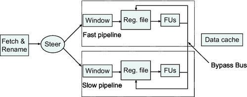
Fields et al. [26] propose a work steering technique which dispatches instructions to functional units with appropriate speed in order to exploit instruction-level slack (Fig. 5). They find that there are instructions that could be delayed without significant impact on the performance. In order to locate instructions, they use off- and online approaches. In the first one, they make dependency graphs to find instructions that produce slack, and they achieve promising results. Even better results they achieve with the online approach where they dynamically predict slack in hardware. Online control policies discussed previously for DVFS in MCD processors cannot treat each instruction individually. There is simply no possibility of dynamically changing the frequency of execution individually for each instruction; instead, the frequency of each domain is adjusted according to the aggregate behavior of all the instructions processed in this domain over the course of a sampling interval. According to Ref. [26], for 68% of the static instructions, 90% of their dynamic instances have enough slack to double their latency. This slack locality allows slack prediction to be based on sparsely sampling dynamic instructions and determining their slack. Their results show that a control policy based on slack prediction is second best, in terms of performance, only to the ideal case of having two fast pipelines instead of a fast and a slow pipeline.
Optimizing Issue Width
One more approach to make balanced low-power core which will consume just necessary energy for its work is to adapt its “working capacity” to its actual workload. Out-of-order processors are known as power hungry solutions and they are suitable for application of aforementioned kinds of techniques. Bahar and Manne [25] propose a dynamic change of the width of an 8-issue processor to 6-issue or 4-issue when the application cannot take advantage of the additional width. They model their target processor after an 8-issue Alpha 21264 [55], comprising two 4-issue clusters (Fig. 6). To switch the processor to 6-issue, one-half of one of the clusters is disabled. To switch to the 4-issue, one whole cluster is disabled.

To disable half or a whole cluster, the appropriate functional units are clock gated. In addition to disabling functional units, part of the instruction queue hardware is also disabled, thus realizing additional power benefits. Decisions are made at the end of a sampling window assuming that the behavior of the program in the last window is a good indicator for the next. This technique can save up to 20% (10%) power from the execution units, 35% (17%) from the instruction queue, and 12% (6%) in total, in the 4-issue (6-issue) low-power mode. However, the power savings for the whole processor are not as dramatic, and Bahar and Manne finally conclude that a single technique alone cannot solve the power consumption problem.
4.1.2 Static and Dynamic
In order to significantly reduce static power/energy, existing DVFS techniques are augmented with adaptive body bias (ABB) techniques.
Combined ABB and DVFS
Reverse Body Biasing (RBB) technique increases the threshold voltage and thus brings an exponential reduction in leakage power. However, the increase in threshold voltage reduces gate overdrive (VDD − Vt), reducing circuit's performance (VDD is voltage of the power supply and Vt threshold voltage). Either scaling VDD or increasing Vt slows down switching. Considering dynamic or leakage power independently, the performance can be traded for power by scaling either VDD or Vt. As in both cases, performance degradation is linear to the scaling of the VDD or Vt, whereas power savings are either quadratic or exponential, the resulting improvement in EDP is substantial.
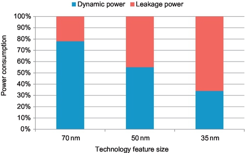
In case that we want to optimize total power (Estat + Edyn), the best approach depends on static/dynamic power ratio. In older technologies, like 70 nm, where dynamic power component is still the dominant one, VDD scaling gives better results. On the contrary, while considering more recent technologies, like 35 nm, RBB provides better savings. DVS/RBB balance is shown in Fig. 7. The balance of dynamic and leakage power shifts across technologies and among different implementations in the same technologies. Additionally, the leakage also changes dynamically as a function of temperature. This aspect, however, has not been researched adequately.
For a given frequency and switching delay, the best possible power savings come from carefully adjusting both VDD and Vt, depending on the balance of dynamic versus leakage power at that point. While the VDD − Vt difference determines switching speed, maximum gains in power consumption come from a combined adjustment of the two. Three independent studies came to the same conclusion.
The work of Duarte et al. [27] studied the impact of scaling on a number of approaches for dynamic power reduction. Among their experiments, they simultaneously scale the supply voltage (VDD) and the body-to-source bias voltage (Vbs), i.e., they simultaneously perform DVS and ABB. Their study is not constrained in any variable, meaning that they examine a wide spectrum of possible values for the two quantities. Their results show a clear advantage over DVS alone.
Martin et al. [28] combine DVS and ABB to lower both dynamic and static power of a microprocessor during execution. They derive closed-form formulas the total power dissipation and the frequency, expressing them as a function of VDD and Vbs. The system-level technique of automatic performance setting was used. In this technique, deadlines are derived from monitoring system calls and interprocess communication. The performance setting algorithm sets the processor frequency for the executing workload so it does not disturb its real-time behavior. Solving the system of the two mentioned equations for a given performance setting, Martin et al. are able to estimate the most profitable combination of VDD and Vbs to maximize power dissipation savings. The approach can deliver savings over DVS alone of 23% in a 180 nm process and 39% in a (predicted) 70 nm process.
Yan [29] studies the application of combined DVS and ABB in heterogeneous distributed real-time embedded systems. In analogy to the work of Martin et al., the author determines the lowest frequency of operation that can satisfy the real-time constraints of an embedded system using the worst-case analysis. In contrast to the previous work, the deadlines are known and are hard real time. Given the required operation frequencies, Yan shows that both VDD and Vt have to scale to obtain the minimum power across the range of frequencies for a 70 nm technology. They notice that for higher frequencies, when dynamic component of power is significant, VDD scaling is more useful. However, for lower frequencies, where static (leakage) power starts to dominate, we should decrease Vbs voltage, i.e., to apply RBB, to make power dissipation lower.
4.2 Core-Pipeline
In this section, the techniques which target complete pipeline (both functional and control units) are presented.
4.2.1 Dynamic
There are three most popular approaches to reduce dynamic energy in pipeline. The first one is clock gating of large power hungry pipeline units and their accompanying latches. The second one is a result from the effort to exploit the bit redundancy in data, while the third one is based on reusing some pieces of already executed code, i.e., generating already computed outputs directly from some memory structure.
Clock Gating
Pipeline blocks are clock gated either if they are known to be idle or if they are supposed to be doing useless work. The first approach (deterministic clock gating) is more conservative and do not spoil performance, while the second one is more “risky” and could degrade performance with, of course, significant power savings.
Deterministic Clock Gating
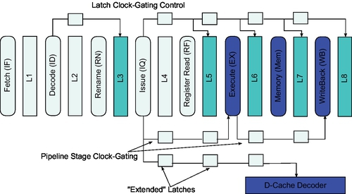
The idea of Deterministic Clock Gating (DCG) application on the pipeline is to clock gate the structures that are known to be idle, without spoiling the performance but decreasing EDP at the same time. Li et al. [30] give a detailed description of DCG in a superscalar pipeline. They consider a high-performance implementation using dynamic domino logic for speed. This means that besides latches, the pipeline stages themselves must be clock gated.
The idea is to find out if a latch or pipeline stage is not going to be used. In Fig. 8 is depicted a pipeline which clock-gate-able parts are shown dark. The Fetch and Decode stages and their latches are, for example, never clock gated since instructions are needed almost every cycle, while there is completely enough time to clock gate functional units.
DCG was evaluated with Wattch [30]. By applying DCG to all the latches and stages described above, they report power savings of 21% and 19% (on average) for the SPEC2000 integer and floating point benchmarks, respectively. They found DCG more promising than pipeline balancing, another clock gating technique.
Although this work is applied to scalar architecture, it is also applicable to other kinds of architectures. An example of an efficient DCG application on functional units for energy-efficient vector architectures can be found in Ref. [57].
Improving Energy Efficiency of Speculative Execution
Although they are necessary in order to keep functional units busy and to have high Instructions Per Cycle (IPC), branch predictors and speculative activity approach are fairly power hungry. Besides the actual power consumption overhead of supporting branch prediction and speculative execution (e.g., prediction structures, support for check pointing, increased run-time state), there is also the issue of incorrect execution.
Manne et al. [31] try to solve this energy inefficiency of speculative activity proposing approach which is named pipeline gating. The idea is to gate and stall the whole pipeline when the processor threads down to very uncertain (execution) paths. Since pipeline gating refrains from executing when confidence in branch prediction is low, it can hardly hurt performance. There are two cases when it does: when execution would eventually turn out to be correct and is stalled, or when incorrect execution had a positive effect on the overall performance (e.g., because of prefetching). On the other hand, it can effectively avoid a considerable amount of incorrect execution and save the corresponding power.
The confidence of branch prediction in Ref. [31] is determined in two ways: counting the number of mispredicted branches that can be detected as low confidence, and the number of low-confidence branch predictions that are turn out to be wrong. They find out that if more than one low-confident branch enters the pipeline, then the chances of going down the wrong path increase significantly. They propose several confidence estimators which details could be found in Ref. [31]. In their test, authors show that certain estimators used for gshare and McFarling application with a gating threshold of 2 (number of low-confident branches), a significant part of incorrect execution, can be eliminated without perceptible impact on performance. Of course, the earlier the pipeline is gated, the more incorrect work is saved. However, this assumes larger penalty of stalling correct execution.
Aragón et al. [32] did similar work but with slightly different approach. Instead of having a single mechanism to stall execution as Manne et al., Aragón et al. examine a range of throttling mechanisms: fetch throttling, decode throttling, and selection-logic throttling. As throttling is performed deeper in the pipeline, its impact on execution is diminished. Thus, fetch throttling at the start of the pipeline is the most aggressive in disrupting execution, starving the whole pipeline from instructions, while decode or selection-logic throttling deeper in the pipeline is progressively less aggressive. This is exploited in relation to branch confidence: the lower the confidence of a branch prediction, the more aggressively the pipeline is throttled. The overall technique is called “selective throttling.”
Pipeline gating, being an all-or-nothing mechanism, is much more sensitive to the quality of the confidence estimator. This is due to the severe impact on performance when the confidence estimation is wrong. Selective throttling, on the other hand, is able to better balance confidence estimation with performance impact and power savings, yielding a better EDP for representative SPEC 2000 and SPEC 95 benchmarks.
Significance Compression
Slightly different approach than previous one is proposed by Canal et al. [33]. The idea is to compress nonsignificant bits (strings of zeros or ones) anywhere they appear in the full width of an operand. Each 32-bit word is augmented with a 3-bit tag describing the significance of each of its four bytes. A byte can be either significant or a sign extension of its preceding byte (i.e., just a string of zeros or ones). The authors report that the majority of values (87%) in SPECint and Mediabench benchmarks can be compressed with significance compression. A good 75% of all values is narrow-width using above-mentioned 16-bit definition (i.e., only the first and possibly second bytes are significant).
Canal et al. propose three kinds of pipeline adapted to work with compressed data. The first one is named byte-serial pipeline where only significant bytes flow through the pipeline and are operated. The rest is carried and stored via their tags. This opens up the possibility of a very low-power byte-serial operation. If more than one significant byte needs to be processed at a pipeline stage, then this stage simply repeats for the significant bytes. However, although activity savings range from 30% to 40% for the various pipeline stages, performance is substantially reduced; CPI increases 79% over a full-width (32-bit) pipeline.
Another, faster, approach is to double pipeline width (byte-parallel pipeline), and this results with 24% performance losses while retaining 30–40% activity savings. Increasing the pipeline width to four bytes (byte-parallel pipeline) and enabling only the parts that correspond to the significant bytes of a word retain most of the activity savings and further improves performance, bringing it very close (6–2% slowdown depending on optimizations) to a full pipeline operating on uncompressed operands.
Work Reuse
Pipeline-level work reuse can be implemented at instruction level or block of instructions (basic block) level.
Instruction-Level Reuse
The work reuse approach can be even more efficient if we reuse the whole instructions, or set of instructions, instead of operations only (Section 4.4.1). Early work on this topic is done by Sodani and Sohi who propose dynamic instruction reuse [34]. The motivation for their work is a discovery that execution in a mispredicted path converges with execution in the correct path resulting in some of the instructions beyond the point of convergence being executed twice, verbatim, in the case of a misprediction. Furthermore, the iterative nature of programs in conjunction with the way code is written modularly to operate on different input results in significant repetition of the same inputs for the same instructions. The results of such instructions can be saved and simply reused when needed rather than reexecuting the computation. Sodani and Sohi claim that in some cases, over 50% of the instructions can be reused in this way. They do not evaluate power saving of their proposals, but their work was actually a step forward to more general and more energy-efficient approach—basic block reuse.
Basic Block-Level Reuse
The basic block reuse is done by Huang and Lilja [35]. Their observations concern whole basic blocks for which they find that their inputs and outputs can be quite regular and predictable. Their study shows, for the SPEC95 benchmarks, a vast majority of basic blocks (90%) have few input and output registers (up to four and five, respectively) and only read and write few memory locations (up to four and two, respectively). A Block History Buffer (BHB) stores inputs and outputs of basic blocks and provides reuse at the basic block level. The increased number of inputs that must match for the result to be determinable means that basic block reuse is not as prevalent as instruction reuse. However, when reuse succeeds, it does not only avoids the execution of the individual instructions in the basic block but also breaks the dependence chains in it, returning results in a single cycle. In addition to the energy saved by not executing instructions in functional units, considerable energy can be also saved because all the bookkeeping activities in the processor (instruction pointer update, instruction fetch, decode, rename, issue, etc.) during the execution of a basic block are eliminated. Depending of the chosen buffer, sometimes, it is more expensive to access and match entries in the buffer since each entry consists of arrays of values and valid bits.
Trace-Level Reuse
One more work reuse approach is proposed by Gonzalez et al. [36]. Traces are groups of consecutive instructions reflecting not their position in the static code layout but their order in dynamic execution. A trace may span more than one basic block by allowing executed branches (taken or nontaken) in the middle of the trace. Similarly to basic blocks, a trace too can start with the same inputs, read the same values from memory, and produce the same results and side effects (e.g., memory writes). Trace-level reuse has analogous problems and benefits with basic block reuse. The problems are actually amplified as the traces can be longer.
Region Reuse
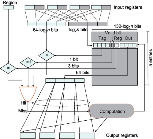
Region reuse stands for exploiting the value locality exhibited by sets of instructions inside a program. These sets of instructions may have different granularity: basic blocks, traces, or even whole functions can be selected as candidates for computation reuse. The classical region reuse mechanism is showed in Fig. 9. The design consists of three different boxes: an input logic box, a reuse table, and a reuse check logic box.
We can obtain more power/energy efficiency when we introduce some acceptable error—tolerant region reuse. Tolerant region reuse improves classical region reuse with significant EDP reduction gains (from 13% to 24%) and consistently reduces both time and energy consumption for the whole span of media applications studied. These gains come at the cost of minor degradation of the output of the applications (noise introduced always bounded to an SNR of 30 dB) which make it ideal for the portable domain where quality vs. form-factor/battery life is a worthy trade-off. The main drawback of tolerant region reuse is the strong reliance on application profiling, the need for careful tuning from the application developer, and the inability of the technique to adapt to the variability of the media contents being used as inputs. To address that inflexibility, Alvarez et al. [37] introduce dynamic tolerant region reuse.
This technique overcomes the drawbacks of tolerant region reuse by allowing the hardware to study the precision quality of the region reuse output. The proposed mechanism allows the programmer to grant a minimum threshold on SNR (signal-to-noise ratio) while letting the technique adapt to the characteristics of the specific application and workload in order to minimize time and energy consumption. This leads to greater energy-delay savings while keeps output error below noticeable levels, avoiding at the same time the need of profiling.
They applied the idea to a set of three different processors, simulated by Simplescalar and Wattch, from low to high end. The used applications are JPEG, H263, and GSM. Alvarez et al. show their technique leads to consistent performance improvements in all of our benchmark programs while reducing energy consumption and EDP savings up to 30%.
4.3 Core-Front-End
Control unit is an unavoidable part of every processor and the key part of out-of-order processors. As out-of-order processors tend to have pretty high EDP factor, there is a lot of room for energy-efficiency improvement.
4.3.1 Dynamic
Beside clock gating, as the most popular dynamic power/energy optimization mechanism, here caching takes a part as well.
Exploiting Narrow-Width Operands
Although low-power research that focus on narrow-width operands exploitation mostly target functional units, this approach can also apply on RFs, and it is done by Ergin et al. [58]. The intent is not so much to reduce power consumption, but to alleviate register pressure by making better use of the available physical registers. Similarly to packing two narrow values in the inputs of functional units or packing compressed lines in caches, multiple narrow values are packed in registers.
A number of these values can be packed in a register either “conservatively” or “speculatively.” Conservatively means that a value is packed only after it is classified as narrow. This happens after a value is created by a functional unit. When a narrow value is packed in a different register than the one it was destined for, the register mapping for the packed value is updated in all the in-flight instructions. In contrast, “speculative packing” takes place in the register renaming stage, without certain knowledge of the width of the packed value. Packing and physical register assignment are performed by predicting the output width of instructions. The prediction history (per instruction) is kept in the instruction cache. The technique works well for performance—increases IPC by 15%.
Instruction Queue Resizing
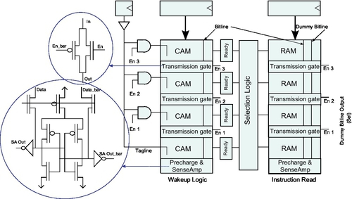
On-demand issue queue resizing, from the power efficiency point of view, was first proposed by Buyuktosunoglu et al. [38]. They propose circuit-level design of an issue queue that uses transmission gate insertion to provide dynamic low cost configurability of size and speed. The idea is to dynamically gather statistics of issue queue activity over intervals of instruction execution. Later on, they use mentioned statistics to change the size of an issue queue organization on the fly to improve issue queue energy and performance.
The design of the IQ is a mixed CAM/SRAM design where each entry has both CAM and SRAM fields. The SRAM fields hold instruction information (such as opcode, destination register, status) and the CAM fields constitute the wakeup logic for the particular entry holding the input operand tags. Results coming from functional units match the operand tags in the CAM fields and select the SRAM part of entry for further action. When an instruction matches both its operands, it becomes “ready” to issue and waits to be picked by the scheduler.
The IQ is divided into large chunks with transmission gates placed at regular intervals on its CAM and SRAM bitlines. The tag match in the CAM fields is enabled by dedicated taglines. Partitioning of the IQ in chunks is controlled by enabling or disabling the transmission gates in the bitlines and the corresponding taglines. The design is depicted in Fig. 10.
Buyuktosunoglu et al. achieve power savings for the IQ 35% (on average) with an IPC degradation of just over 4%, for some of the integer SPEC2000 benchmarks, on a simulated 4-issue processor with a 32-entry issue queue.
Ponomarev et al. go one step further, making the problem more generalized by examining total power of main three structures of instruction scheduling mechanisms: IQ, Load/Store Queue (LSQ), and Reorder Buffer (ROB) [39]. They notice that IPC-based feedback control proposed by Ref. [38] does not really reflect the true needs of the program but actually depend on many other factors: cache miss rates, branch misprediction rates, amount of instruction-level parallelism, occupancy, etc. Hence, they considered occupancy of a structure as the appropriate feedback control mechanism for resizing.
The proposed feedback scheme measures occupancy of each of three main structures and makes decisions at the end of the sample period. The mechanism allows on-demand resizing IQ, LSQ, and ROB, by increasing/decreasing their size according to the actual state. In simulations for a 4-issue processor, this method yields power savings for the three structures in excess of 50% with a performance loss of less than 5%.
A different approach to the same goal (dynamically IQ adaption for power savings) is proposed by Folegnani et al. [40]. Instead of disabling large chunks at a time, they disable individual IQ entries. Another difference to the previous two approaches is that IQ is not limited physically but logically. Actually, they organized IQ as FIFO buffer with its head and tail pointers (Fig. 11). Novelty is the introduction of a new pointer, called the limit pointer which always moves at a fixed offset from the head pointer. This pointer limits the logical size of the instruction queue by excluding the entries between the head pointer and itself from being allocated.
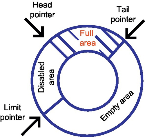
They resize the IQ to fit program needs. Unused part is disabled in a sense that empty entries need not participate in the tag match; thus, significant power savings are possible. The feedback control is done using a heuristic with empirically chosen parameters. The IQ is logically divided into 16 partitions. The idea for the heuristic is to measure the contribution to performance from the youngest partition of the IQ which is the partition allocated most recently at the tail pointer. The contribution of a partition is measured in terms of issued instructions from this partition within a time window. If that contribution is below some empirically chosen threshold, then the effective size of the IQ is reduced by expanding the disabled area. The effective IQ size is periodically increased (by contracting the disabled area). This simple scheme increases the energy savings to about 91% with a modest 1.7% IPC loss.
Loop Cache
The loop cache is designed to hold small loops commonly found in media and DSP workloads [41, 43]. It is typically just a piece of SRAM that is software or compiler controlled. A small loop is loaded in the loop buffer under program control and execution resumes, fetching instructions from the loop buffer rather than from the usual fetch path. The loop buffer being a tiny piece of RAM is very efficient in supplying instructions, avoiding the accesses to the much more power-consuming instruction L1. Because the loop buffer caches a small block of consecutive instructions, no tags and no tag comparisons are needed for addressing its contents. Instead, only relative addressing from the start of the loop is enough to generate an index in order to correctly access all the loop instructions in the buffer. Lack of tags and tag comparisons makes the loop buffer far more efficient than a typical cache.
Fully automatic loop caches, which detect small loops at run-time and install them in the loop cache dynamically, are also proposed in Refs. [42–44]. However, such dynamic proposals, although they enhance the generality of the loop cache at the expense of additional hardware, are not critical for the DSP and embedded world where loop buffers have been successfully deployed. Nevertheless, the fully automatic loop buffer appears in Intel's Core 2 architecture [59].
Trace Cache
Due to CISC nature of the IA-32 (x86) instruction set processors, that translate the IA-32 instructions into RISC-like instructions called uops, the work required in such a control unit is tremendous, and this is reflected in the large percentage (28%) of the total power devoted to the control unit. To address this problem, Solomon et al. [45] describe a trace cache that can eliminate the repeated work of fetching, decoding, and translating the same instructions over and over again. Called the Micro-Operation Cache (UC), the concept was implemented as the trace cache of the Pentium-4 [60]. The reason why it works so well in this environment is that traces are created after the IA-32 instructions are decoded and translated in uops. Traces are uop sequences and are directly issued as such.
The Micro-Operation Cache concept is depicted in Fig. 12. The UC fill part starts after the instruction decode. A fill buffer is filled with uops until the first branch is encountered. In this respect, the UC is more a basic BHB than a trace cache, but this is not an inherent limitation in the designs; it was so chosen just to make it as efficient as possible. Another interesting characteristic of the UC design is that, although a hit can be determined in the UC during the first pipeline stage, the uops are not delivered to the issue stage until after four more cycles (stages). This ensures that there is no bubble in the pipeline switching back and forth from streaming uops out of the Control Unit (CU) to fetching IA-32 instructions from the instruction cache and decoding them.

The benefits for often repeating traces, of course, are significant. Solomon et al. report that 75% of all instruction decoding (hence, uop translation) is eliminated using a moderately sized micro-operation cache. This is translated to a 10% reduction of the processor's total power for the Intel's P6 architecture[61]. The Pentium-4 trace cache is a prime example of a power-saving technique eliminating repetitive and cacheable computation (decoding).
4.3.2 Static
The ROB and the RF are the two critical components to enhance a processor's ILP but, unfortunately, they have serious static power, especially occurred in a large RF which in average consumes around 20% of the processor's power budget. The RF shows the highest power density as it has a severe access frequency and occupies a relatively small area. As a result, due to high areal power density, the RF is known to the hottest unit in the microprocessor [62].
Idle Register File DVS
During program execution, RF dissipates two types of static power. First, between the instruction issue stage and commit stage, the register does not store useful values, but waits for instruction commitment, thus waste static energy/power. The second type occurs when a register stores a temporary value which is no longer to be used or may be referenced again but after a long time. In this case, because most consumer instructions nearby the producer have already read out that value from the ROB, it is possible that the register keeps a useless value for a long time without any references. In some cases, the short-lived values even let allocated registers never be referenced once after the instruction issue stage. In Ref. [46], they find that more than 70% values in a program are short lived.
To address mentioned RF inefficiency problem, Shieh and Chen [46] proposed monitoring mechanism in the datapath and ROB to find out which temporary values possibly make registers have more static power. To prevent the first type of mentioned static power components, the mechanism identifies that a register will temporarily become idle after the instruction issue stage. Because the allocated register will not be referenced during instruction execution until the commit stage, the monitoring mechanism has the ability to monitor each register's usage along pipeline stages.
To prevent the second-type static power, identify that a register possibly stores a “seldom-used” temporary value. They added a simple indicator in each ROB entry to monitor, for each temporary value, how many consumer instructions have appeared before commitment. If a temporary value has many consumers appearing before commitment, the probability that this value becomes “seldom-used” after commitment will become very large.
Their monitoring mechanism cooperates with the DVS mechanism. When it identifies that a register is idle, it triggers the DVS mechanism to power down that register's supply voltage to lower voltage levels. If the monitoring mechanism finds that a register will be accessed soon (e.g., at the stage just before instruction reference or commitment), it early alerts the DVS mechanism to power on that register's supply voltage to the normal voltage level. They assumed that each register has three voltage levels: active (1 V), drowsy (0.3 V), and destroy (0 V).
Simulation results show that through ROB monitoring, a RF can save at least 50% static power consumption with almost negligible performance loss.
Register File Access Optimization
A problem with RF accesses is that they are not spread through the whole RF, but clustered on one of its side (Fig. 13).

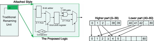
Kim et al. [47] proposed an idea that evenly redistributes accesses to the full range of the RF through the improvement of the traditional renaming unit. By uniformly distributing writing accesses to the RF, the power density decreases and the possibility of hotspots forming also reduces. Consequently, the leakage power decreases as it is proportional to the exponential function of temperature.
The proposed is actually a remapping technique revealing that architectural registers (i.e., entry number 0–40) are relocated to the full range of entry numbers (i.e., 0–79) with only the even number allocation, and also that the assignments to physical registers (i.e., 40–80) are also repositioned throughout whole RF area (i.e., 1–80) with the odd number. The algorithm is realized through several steps. First, the traditional renaming unit allocates an index number of a physical register entry to an architectural register. Next, a new index number is generated by our simple algorithm; if the index number is less than 40, then a new index number will be achieved from multiplying the first index number by 2; otherwise (i.e., 40–80), we subtract 40 from the first index, multiply it by 2, and add 1. These simple algorithms can be implemented by a small logic, and the logic can be attached to the traditional renaming unit; the attached logic consists of six small components: an 8-bit adder, an 8-bit shift register, a comparator, an OR gate, and two 2:1 multiplexors (Fig. 14). The authors report notable temperature drop reaching up to 11% on average 6%, and leakage power savings reached up to 24% on average 13%.
4.4 Core-Back-End
Functional units are a fundamental part of every processor. They provide a lot of trade-off; thus, plenty of techniques for both dynamic and static power/energy components have been proposed.
4.4.1 Dynamic
The essence of almost all dynamic power/energy optimization techniques for this part of the processor is clock gating.
Exploiting Narrow-Width Operands
The first approach optimizes the integer structures and the results are still 100% accurate, while the second one optimizes Floating Point (FP) units and introduce some error.
Integers
Each processor has defined its data width, and it is one of its main characteristics. Often, applications running on a processor do not really need full data width. It has become especially evident in 64-bit processors. Brooks and Martonosi [49] notice a disproportion through a set of measurements they did for SPECint95 and MediaBench application running on 64-bit Alpha machines and find useful statistics. They find a lot of operations where the both operands have the number of significant bit of 16 and 33, respectively.
There are two ways to exploit this characteristic. One reduces power while the other improves performance. They both have the same goal—to improve energy and EDP. In the both of the cases, the first step is the same—detect narrow operands. Brooks and Martonosi [49] consider each 16-bit, or less wide, as narrow operand. They do detection dynamically by tagging ALU and memory outputs with “narrow bit” if it is narrow.
First approach is to clock gate unused part of ALU when we have two narrow operands (Fig. 15). This technique yields significant power savings for the integer unit comprising of an adder, a booth multiplier, bit-wise logic, and a shifter. Specifically, in an Alpha-class, 4-instruction-wide superscalar, the average power consumption of the integer units can be reduced by 55% and 58% for the SPECint95 and the Mediabench benchmark suites, respectively.
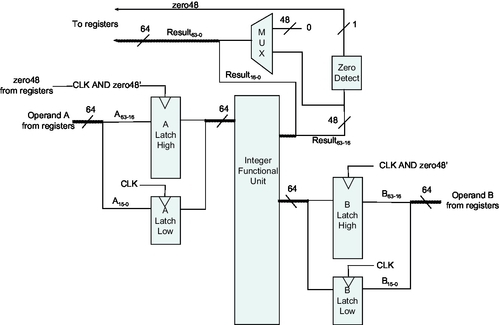
Another approach is to pack two narrow operands and to process it simultaneously. This is done by detecting two narrow-operand instructions which are ready to execute and shifting significant part of the one to high order part (which is “empty”) of the other. The combined operations are executed in the ALU in Single Instruction, Multiple Data (SIMD) mode, similarly to SIMD multimedia extension instructions. The problem with the packing approach is overhead logic (mainly MUXs) which spoils energy savings.
However, the above-presented packing narrow-width values approach does not achieve significant speedup. The improvement of this approach is to introduce speculation in the methodology. We suppose that both operands are narrow, pack them like in the normal case, and if we find we were wrong, squash and reexecute them separately. This optimization brings the speedup of packing narrow-width operations to approximately 4% for SPECint95 and 8% for MediaBench for an Alpha-class, 4-instruction-wide, superscalar CPU. Speedup increases with the width of the machine as more instructions become available to choose from and pack together.
Floating Point
While the above exploitation of narrow operands relies on keeping accuracy, one step further to be more energy efficient is to introduce some “acceptable” error. Acceptable is a very relative term, and it strongly depends on the application's nature. Tong et al. [48] analyze several floating point programs that utilize low-resolution sensory data and notice that the programs suffer almost no loss of accuracy even with a significant reduction in bit-width. Figure 16A shows how program accuracy decreases when we utilize lower number on mantissa bits, while Fig. 16B shows program accuracy across various exponent bit-widths.


Tong et al. exploit this characteristic of applications they profiled by proposing the use of a variable bit-width floating point unit to reduce power consumption. To create hardware capable of variable bit-width multiplications (up to 24 × 24 bit), they used a 24 × 8 bit digit-serial architecture (Fig. 17). The 24 × 8 bit architecture allows performing 8, 16, and 24-bit multiplication by passing the data once, twice, or three times through the serial multiplier. A finite state machine is used to control the number of iterations through the CSA array.

Proposed FP architecture was compared with widely used Wallace architecture. Figure 18 shows the potential power reduction for our three programs if we use the digit-serial multiplier as the mantissa multiplier. For 8-bit multiplication, the digit-serial multiplier consumes less than 1/3 of power than the Wallace Tree multiplier (in the case of Sphinx and ALVINN). When 9–16 bits of the mantissa are required (in the case of PCASYS and Bench22), the digit-serial multiplier still consumes 20% less power than the Wallace Tree multiplier. The digit-serial multiplier does consume 40% more power when performing 24-bit multiplication due to the power consumption of the overhead circuitry.
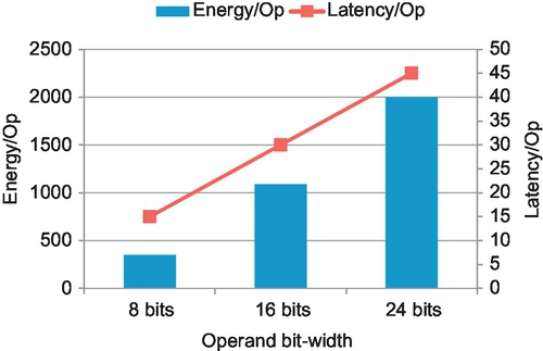
Work Reuse
The idea of the application of the work reuse technique on functional units is to cache the results and to reuse them later instead of recompute them. This can save considerable power if the difference in energy between accessing the cache and recomputing the results is quite large. The first work in this topic is done by Citron et al. [51]. This act of remembering the result of an operation in relation to its inputs they named memoization. A memoization cache, or Look-up Table (LUT), stores the input operands and the result of floating point operations. Upon seeing the same operands, the result is retrieved from the Memo-table and is multiplexed onto the output (Fig. 19). The Memo-table access and the floating point operation start simultaneously. However, accessing the Memo-table is much faster (single-cycle) than performing the actual multicycle operation. Since the result is available much earlier, this translates into performance benefits but also (by gating the floating point unit before it completes the operation) to power benefits. The power benefits are commensurable to the energy differential between accessing the cache and performing the operation to completion.

Although in Ref. [51] they do not perform any power analysis, they do statistics for multimedia applications (effect benchmark suite, SPEC FP95, and imaging/DSP applications) which, in conjunction with simple power models for the floating point unit and the memo-tables, can be used to derive power estimates. For their workloads, 59% of integer multiplications, 43% of FP multiplications, and 50% of FP divisions are memoizable and can be “performed” in a single cycle with small (32-entry, 4-way set-associative) LUTs.
The work from Alvarez et al. [52] is a kind of mixture of previous presented technique and the technique from Tong et al. [48]. In order to achieve more power savings from memoization (i.e., higher reuse), they play with human perception tolerance and propose technique called tolerant memoization which targets low-power embedded processors for hand-held devices with multimedia workloads. Performance and power dissipation can be improved at the cost of small precision losses in computation. The key idea is to associate entries with the similar inputs to the same output. They targeted low-power processors for hand-held devices with multimedia workloads.
Except the ability to have a hit when the inputs are not exactly the same, the rest of the proposed hardware (Fig. 20) is more or less the same as in the previously presented technique. The additional option is a possibility to serial LUT memoization, which means that FPU waits until it is known if there is a hit in the LUT or miss. In that way, the hardware is slower but more power efficient. The results showed when only a low hit rate is achieved (classical reuse and speech), parallel configuration works better as it saves some energy but does not increase the operation latency. When the hit rate grows, serial configuration arises as the best solution because it only infrequently uses one more cycle, but often saves the entire energy of the FPU; therefore, serial configuration is the best choice for tolerant reuse.

With tolerant memoization and realistic table sizes, the reuse hit rate is raised and, as a result, considerable power and time savings are achieved (up to a 25% improvement in the EDP for some of the benchmarks) at the cost of introducing some errors in the output data that are negligible in the context of hand-held devices.
4.4.2 Static
While dynamic power/energy optimization techniques are mostly based on clock gating, here this is the case with power gating.
Power Gating
Power gating of functional units is not used to be as attractive as power gating memory cells. Due to short idle intervals, it is a question if we save anything as we spend dynamic energy to power them up or down. However, as leakage becoming dominant component of total power consumption, power gating is getting more attractive. Hu et al. [53] make an analysis of power gating application on functional units. They propose analytical formulas that, for a number of assumptions, yield break-even point, in cycles, for power gating functional units. To simplify the formulas, a leakage factor L is introduced, which specifies the ratio of the average leakage power to the average switching power dissipated per cycle by a functional unit.
They proposed two policies for fine grain functional unit power gating: a time-based policy (functional unit decay) and an event-guided policy (event guided power-gating).
The first policy is based on idle time detection. As soon as an idle period is detected, the functional unit is switched-off. There are three timing factors that determine the behavior of this approach:
1. the break-even point in cycles after which there are net gains in energy,
2. the time it takes for the functional unit to wake up from the moment it is needed, and
3. the decay interval, i.e., the time it takes to decide to put the functional unit in sleep mode.
The first two are technology and functional-unit specific, while the third, the decay interval, is an architectural knob that one can turn to tune the policy. Functional unit design can vary a lot, and this affects the first two of factors. Floating point functional units tend to have a wide range of idle periods (in SPEC-FP 2000). Although their short idle periods are more numerous than their longer ones, most idle cycles are due to the longer periods by virtue of their size. In this case, a long decay interval skips the short idle periods and selects only the large ones. This minimizes the number of times the functional units are unavailable because they are powered down while still benefiting by having the functional unit powered down for a significant part of the time. Overall, this technique can power down the floating point units for 28% of the time with only minimal performance penalty (less than 2%) for the SPEC FP 2000. For integers, the situation with short idle periods is even worse as the integer unit is often used by address arithmetic and longer idle periods usually occur after L2 misses.
In order to increase power savings in applications during which executions there are a lot of short idle periods, Hu et al. propose event-guided power gating. They used various events as L2 misses, instruction cache misses, or branch mispredictions as clues to upcoming idleness of the functional units. Upon detecting a misprediction, the functional units are put immediately into sleep mode without waiting for the normal decay interval.
This simple rule extends the powered-down time of the functional units without incurring any additional performance penalty. The use of clues increases the percentage of cycles in sleep mode for a given performance loss, or, conversely, for the same percentage of cycles in sleep mode the use of clues eases the performance impact. Similarly to branch mispredictions, other events can also provide useful hints for the idleness of the functional units but have not been studied further.
Vt-Based Technique
As the design of functional units demands maximum speed, in most cases, they are built using domino logic. The problem with domino logic, from the low power point of view, is that every cycle domino logic is charged and discharged (sometimes) by the evaluation of its inputs, thus preventing only input from switching is not enough to stop energy to drain! With respect to static power, leakage paths in dynamic domino logic depend on the state of the internal dynamic nodes. This property is exploited for the implementation of a sleep mode specific to domino logic.
The solution is to use MTCMOS approach by selectively using high Vt devices in the noncritical paths [54]. In that case, the performance is not compromised. In Fig. 21, the integration of high-VT devices (shaded transistors) in the domino-logic AND gate is showed. If either input is low, the dynamic node remains charged, resulting in a large subthreshold leakage current through the high-leakage transistors N1, N2, N3, and N4. However, when the dynamic node is discharged, the low leakage transistors P1, P2, and N5 are strongly cut-off, and the leakage in the whole circuit is dramatically reduced.

A step further to be more power efficient is to apply power gating on the existing low leakage domino AND circuit. The challenges are almost the same as in CMOS power gating—the short idle periods. An overly aggressive policy to enter the sleep mode is probably not optimal. For this reason, Dropsho et al. propose a gradual sleep policy that puts the functional unit in sleep mode in stages by adding additional sleep transistor to the existing low leakage asymmetric circuit (Fig. 22). The gradual sleep technique is shown in Fig. 23. The functional unit is divided into slices which are put in sleep mode consecutively as long as the functional unit remains idle. As soon as it is needed again, all slices are brought back to active mode and are precharged.


They show that the simple GradualSleep design works well across a range of technology and application parameters by amortizing the energy cost of entering the sleep mode across several cycles.
4.5 Conclusion About the Existing Solutions
From the above presented, we can conclude that only comprehensive approach to optimize the components of power/energy of microprocessors can lead to the significant savings. Thus, it is very important to consider all the possible optimization solutions during the design process. Blind DVFS application, for example, could increase total energy consumption! For instance, Miyoshi et al. [63] concluded that for Pentium-based system, it is energy efficient to run only at the highest frequency, while on the PowerPC-based system, it is more energy efficient to run at the lowest frequency point.
There are a lot of possible solutions to reduce power/energy at each level; thus, there are situations when we wonder which technique to apply. For example, if we consider core-level techniques, one of the first decisions is the selection of power management: software (OS) or hardware (on-chip) one. Then we should pick adequate management strategy. There are off-line (compiler-based) and online strategies. The online strategies can be based on events or predictions. Low-power design is a process which needs a lot of time and effort, and there are a lot of questions that need to be answered. It essentially important to consider savings/overhead balance before we apply a particular technique; otherwise, we can make the system even less efficient.
Generally, it is always important to consider Amdahl's law. Before starting optimization process, we should first examine the percentage that a component being optimized takes in total power budget.
5 Future Trend
It is becoming obvious that due to the “power wall” further scaling is in crisis. While sole core scaling saturated, the relief was Chip-Multiprocessor (CMP). Unfortunately, it is a matter of time when the same will happen with CMP scaling. An essential question is how much more performance can be extracted from the multicore path in the near future.
The study on this topic is performed by Esmaeilzadeh et al. [64]. The multicore designs they study include single-threaded CPU-like and massively threaded GPU-like multicore chip organizations with symmetric, asymmetric, dynamic, and composed topologies with PARSEC benchmark. Unfortunately, the results are not optimistic! Even at 22 nm, 21% of a fixed-size chip must be powered off, and at 8 nm, this number grows to more than 50%. This turned off part of the core we call “dark silicon.” Through 2024, only 7.9 × average speedup is possible across commonly used parallel workloads, leaving a nearly 24-fold gap from a target of doubled performance per generation. Results for ITRS scaling are slightly better but not much. With conservative scaling, a speedup gap of at least 22 × exists at the 8 nm technology node compared to Moore's law. Assuming ITRS scaling, the gap is at least 13 × at 8 nm.
They conclude that radical microarchitectural innovations are necessary to alter the power/performance pareto frontier to deliver speedup commensurate with Moore's law. Actually, maybe the solutions are microelectronics innovations rather than microarchitectural ones. Due to many predictions, CMOS will be replaced in next 10 years. Thus, we will again have the situation where fundamental physics and truly adventurous electrical engineering can again play a central role in the evolution of the information technology.
There are several possible MOSFET replacements. Especially interesting are Nanoelectromechanical Systems (NEMS)-based switchers that reliably open and close trillions of times and emulate closer to the ideal switch. Those devices physically move the actual gate up and down depending upon the applied gate voltage. The main characteristic of NEMS devices is their huge resistance when they are off and ultra small resistance when they are on.
6 Conclusion
We presented a comprehensive overview of power- and energy-efficient techniques for microprocessor architecture. The goal is to summarize the work done in low-power area. In past 20 years, low-power area evaluated from marginal topic of computer architecture community to unavoidable part of contemporary architecture research. Although today we care about power more than ever, we should keep being holistic and consider power together with other design goals as performance, reliability, design verifiability, etc.
This overview is beneficial for everyone who is interested in low-power design. Nevertheless, computer architects are the ones who should take the most benefit from this research. The presented low-power solutions are presented in a way that is the most appropriate for them. Software-oriented architects can profit from this overview too.
While dynamic power optimization techniques like DVFS have become enough mature and it is not very probable that we are going to harvest more from them in the future, reducing leakage power is currently the main “obsession” of microprocessor designers. Leakage reduction management is for sure one of the key areas of future architecture-level power research.
Power gating is still the most popular technique to reduce leakage power, especially with its latest incarnation of Per-Core Power Gating (PCPG). Unfortunately, due to growing gate leakage current, the technique is getting less efficient. The situation is currently under control due to the introduction of high-k dielectrics and the whole chip body biasing, but with further technology scaling things are going to be more complicated.
In order to keep power gating efficient, we need more efficient switchers. One of the possible solutions is NEMS-based switcher. With that kind of switcher, we could expect to have ignorable gate leakage current.
Clock gating, although already an intensively utilized approach, is still an indispensable tool to reduce switching activity. Moreover, there is still room to further reduce switching activity of energy-inefficient out-of-order logic of performance-oriented processors.
At the end, it is important to stress that only systematic and comprehensive approach including all the relevant factors can lead us to a successful low-power design. It is crucial that a microprocessor designer considers the whole processor-system power dissipation and its workload rather than a sole component. There are situations when core-only optimizations lead to the system power dissipation increase [65]. It is also very important to adapt the software to the target architecture. The code indeed affects power dissipation in some cases [66]; thus, we should follow the motto: let hardware and software work together.
It is more than obvious that CMOS scaling does not really help anymore; it even makes the problem worse. The only solution on which we could rely today in order to control energy consumption and power dissipation is to apply different techniques to all designing levels. While we do not get the new technology, we need to invent new and to improve existing techniques in order keep power dissipation and energy consumption below the purpose critical values.