Chapter 11
Edit for Credit
IN THIS CHAPTER
![]() Moving, copying, and stretching objects
Moving, copying, and stretching objects
![]() Manipulating whole objects
Manipulating whole objects
![]() Changing pieces of objects
Changing pieces of objects
![]() Fixing your mistakes — oops, I mean changing your mind
Fixing your mistakes — oops, I mean changing your mind
![]() Grip editing
Grip editing
In Chapter 10, you can see that AutoCAD offers several methods of modifying objects in drawings. You can see how to select objects so that you can edit them. Now it’s time to roll up your sleeves and get dirty. In this chapter, I introduce you to the primary editing commands in AutoCAD.
The following sections cover the most important editing commands in AutoCAD, using command-first editing mode. AutoCAD calls commands that edit modify commands.
 As I explain in Chapter 10, command-first editing (or verb-noun editing, in AutoCAD-ese) is one of three approaches to modifying objects in AutoCAD. I concentrate on this method, where you start a command and then pick the objects on which the command will act, because it’s the only method that works for every editing command in AutoCAD.
Assembling Your AutoCAD Toolkit
Table 11-1 lists AutoCAD’s most frequently used editing commands. It shows the tool icons found on the Ribbon’s Modify tab and it lists the official command names with their corresponding aliases, where they exist, in case you prefer typing over clicking.
TABLE 11-1 AutoCAD’s Modify (Editing) Commands
Button | Command |
|---|---|
| ARRAYEDIT |
| ARRAYPATH |
| ARRAYPOLAR |
| ARRAYRECT |
| BLEND |
| BREAK (BR); one point |
| BREAK (BR); two points |
| CHAMFER (CHA) |
| COPY (CO or CP) |
| ERASE (E) |
| EXPLODE (X) |
| EXTEND (EX) |
| FILLET (F) |
| JOIN (J) |
| LENGTHEN (LEN) |
| MIRROR (MI) |
| MOVE (M) |
| OFFSET (O) |
| OVERKILL |
| PEDIT (PE) |
| REVERSE |
| ROTATE (RO) |
| SCALE (SC) |
| STRETCH (S) |
| TRIM (TR) |
The -ARray command underwent a massive revision in AutoCAD 2012; however, I think that there’s still a need for simple arrays (that is, copies of objects in regular patterns), so I explain in this chapter how to create those. In addition, you will probably run into a great many existing drawings that were produced using the older process. The four Array commands shown in Table 11-1 run the new associative array functions that I cover in Chapter 18; I include them here because they’re grouped with the other Modify commands on the Ribbon.
No matter how you start an editing command, AutoCAD in almost all cases prompts you to select objects, points, distances, and/or options at the command line. Read each prompt during every step of the command, especially when you’re figuring out how to use a new one. When all else fails, read the command line!
As I describe in Chapter 8, maintaining precision when you draw and edit is crucial to good CAD work. Nothing ruins a drawing faster than eyeball editing, in which you shove objects around without worrying about precise distances and geometric points.
 Users of Windows Paint and other bitmap drawing programs may be familiar with the concept of nudging — selecting objects and using the arrow keys to move them a certain number of pixels horizontally or vertically. For better or worse, AutoCAD has joined the nudging party. You can move a selected object a pixel’s-worth this way or that way by holding down the Ctrl key and pressing an arrow key. When working with AutoCAD, you always should use tried-and-true precision drafting techniques because moving objects by the pixel (instead of by real-world units) is the opposite of precise. You can move pieces of text by nudging them, but never move actual drawing geometry that way.
The Big Three: Move, COpy, and Stretch
Moving, copying, and stretching are, for many drafters, the three most common editing operations. AutoCAD obliges this need by supplying the Move, COpy, and Stretch commands.
Base points and displacements
The Move, COpy, and Stretch commands each require that you specify how far and in which direction you want objects to be moved, copied, or stretched. After you start the command and have selected objects to be edited, AutoCAD prompts you for these two pieces of information:
Specify base point or [Displacement] <Displacement>:
Specify second point or <use first point as displacement>:
For the first prompt, you pick a point (AutoCAD calls this the base point)_or you enter D to specify a displacement, as described next.
In a subtle way, the second prompt says that you have two methods to specify how far and in which direction you want the objects to be copied, moved, or stretched:
- Pick or type the coordinates of a second point. AutoCAD calls second coordinate point the, uh, the second point. Imagine an arrow pointing from the base point to the second point — the arrow defines how far and in which direction the objects are copied, moved, or stretched.
- Supply an X,Y pair of numbers that represents a distance rather than a point. This distance is the absolute displacement (distance and direction) that you want to copy, move, or stretch the objects.
How does AutoCAD know whether your response to the first prompt is a base point or a displacement? It depends on how you respond to the second prompt. First, pick a point onscreen or enter coordinates at the Base point prompt. Next, there are two possibilities:
- When you pick or type the coordinates of a point at the second point prompt: AutoCAD says, “A-ha! — you want a displacement vector,” and moves the objects according to the imaginary arrow pointing from the base point to the second point.
- When you press Enter at the second prompt (without having supplied any information): AutoCAD says, “A-ha! — you want displacement distance,” and uses the X,Y pair of numbers that you supplied at the first prompt as an absolute displacement distance relative to the drawing’s origin.
What makes this displacement business interesting is that AutoCAD lets you pick a point at the first prompt and then press Enter at the second prompt. AutoCAD still says, “A-ha! — displacement distance,” but now it treats the coordinates of the point you picked as an absolute distance relative to the drawing’s origin at 0,0. If the point you picked has relatively large coordinates, you had better hope that the selected objects are wearing their thermal underwear because they’ll end up somewhere in the northeast of Greenland. You probably won’t see where they’ve gone — because you’ll typically be zoomed into a normal part of the drawing area, the objects will seem to vanish! Use the Z A command to locate them, or press U to undo the action.
When you start the Move, COpy, or Stretch command, press Enter in response to the second prompt only when you want AutoCAD to use your response to the first prompt as an absolute displacement. If you make a mistake, click Undo or press Ctrl+Z to back up and try again. You can use the Zoom All command (described in Chapter 5) to look for objects that have flown off the screen.
Move
The steps in this section demonstrate command-first editing with the Move command, using the base point/second point method of indicating how far and in what direction to move the selected objects. Follow these steps to use precision techniques when you use the Move command:
- Press Esc to make sure that no command is active and no objects are selected.
 Click the Move button on the Modify panel of the Home tab.
The command line displays the
Select objectsprompt.Select at least one object.
You can use any of the object selection techniques described in Chapter 10.
Press Enter when you finish selecting objects.
AutoCAD displays the following prompt:
Specify base point or [Displacement] <Displacement>:Specify a base point by clicking a point or typing coordinates.
This point serves as the tail end of the imaginary arrow that indicates how far and in what direction you want the objects to move. After you pick a base point, it’s fairly easy to see what’s going on, because AutoCAD displays a temporary image of the object that moves around as you move the cursor. As well, it shows a brown dashed line indicating the move vector. Figure 11-1 shows what the screen looks like.
 Specify a base point somewhere on or near the object(s) that you’re moving. You can (and most of the time should) use an object snap mode to choose a point exactly on one of the objects.
AutoCAD displays the following prompt:
Specify second point or <use first point as displacement>:
FIGURE 11-1: Dragging objects in the middle of the Move command.
Specify the second point by clicking a point or typing coordinates.
The second point serves as the arrow end of the imaginary displacement arrow. After you specify the second point, AutoCAD moves the objects.
Press Enter in response to the second prompt only if you want AutoCAD to use your response to the first prompt as an absolute displacement.
AutoCAD has two common precision techniques for specifying the second point:
- Use an object snap mode to pick a second point exactly on the part of another object in the drawing.
- Use direct distance entry to move objects in an orthogonal or polar-tracking direction. See Chapters 6 and 8 for instructions.
The following steps demonstrate command-first editing with the Move command, using the distance method to indicate how far and in what direction to move selected objects:
- Repeat Steps 1–4 in the preceding step list.
- When AutoCAD displays the
Specify base point…prompt, specify a direction and distance by typing the appropriate values:- Enter 6,2, for example, to move selected objects 6 units to the right and 2 units up.
- Enter 3<45, for example, to move selected objects 3 units at an angle of 45 degrees counterclockwise from the east (3 o’clock).
- Press Enter to complete the move.
COpy
![]() The COpy command works almost identically to the Move command except that AutoCAD leaves the selected objects in place and makes copies of them at the new location.
The COpy command works almost identically to the Move command except that AutoCAD leaves the selected objects in place and makes copies of them at the new location.
The COpy command creates multiple copies by default. If you want only one copy, press Enter after placing the first copy in the drawing. Choosing mOde at the command prompt or in the Dynamic Input options list lets you switch between making a single copy and multiple copies. Whether you mostly make multiple copies or mostly make single copies, you’ll appreciate being able to change the default setting.
The COpy command includes an Array option. In addition to plunking down copied objects just about anywhere, type A to choose the Array option and specify spacing for an evenly laid-out linear array, a single row of copies. Using the -ARray command (which I describe later in this chapter and in Chapter 18) is required to create rows and columns or circular patterns of copied objects.
The COpy command includes the Undo option, with which you can roll back multiple copies while in the COpy command.
Copy between drawings
You can’t use AutoCAD’s COpy command to copy objects to another drawing. Instead, you can drag objects from one drawing window to another. As well, you can use the most common Clipboard command, COPYCLIP, together with its companion command, PASTECLIP, to copy and paste objects between drawings.
COPYCLIP, CUTCLIP, and PASTECLIP — the three standard Clipboard buttons you find in every Windows program — use the Windows Clipboard to temporarily store drawing objects from one drawing so that they can be pasted into the same drawing or into other documents, such as another AutoCAD drawing or a Word document. The Clipboard panel on the Ribbon’s Home tab contains several variation of the Cut, Copy, and Paste tools.
Windows also offers a Clipboard history (as of the 2018 release of Windows 10). It remembers the last ten pieces of text and images you copied or cut from a document, including from AutoCAD drawings. To access the history, press Windows key+V, and then choose the item to paste into the current document.
You also can paste text into the command line, and if AutoCAD understands it, it will act on it. Examples of valid text include command names, scripts, and pieces of AutoLISP and Diesel code. The last three are examples of programming possible in AutoCAD, a topic I do not cover in this book.
As you’re figuring out where commands lurk on the AutoCAD Ribbon, the standard Windows keyboard shortcuts — Ctrl+X (cut), Ctrl+C (copy), and Ctrl+V (paste) — are available and are often the most efficient ways of using the Windows Clipboard. Better yet, they even work in a single drawing and between drawings. Within certain limitations, you can also Ctrl+X (cut), Ctrl+C (copy), and Ctrl+V (paste) between AutoCAD drawings and many other Windows applications, although this process may not be the best to use in many situations. I discuss this topic a little more in Chapter 24.
AutoCAD has a total of ten Windows Clipboard commands, nine of which are on the Ribbon. Of the remaining ones, PASTEBLOCK (Ctrl+Shift+V) can sometimes be convenient. It pastes a previous Windows Clipboard selection as a block, which I discuss in Chapter 17. A description of the remaining modes, which are rarely used, is beyond the scope of this book.
Stretch
The Stretch command has the same base point and displacement prompts as COpy and Move, and it shifts objects to other locations in the drawing. But it has this important difference: It can move part of an object or parts of several objects, leaving the rest unscathed. You can use it to change the length of lines, arcs, and rectangles, for example.
Here are the things you need to know to make Stretch your friend:
- Select objects to stretch: To use Stretch to change the length of objects, you must first select objects by using a crossing selection box or crossing polygon, as described in Chapter 10. See Figure 11-2.
- Define points: Stretch operates on the defining points of objects (endpoints of lines, vertices of polylines, and the centers of circles, for example) according to this rule: When a defining point is in the crossing selection box that you specify, AutoCAD moves the defining point and updates the object accordingly. For example, if the crossing selection box surrounds one endpoint of a line but not the other, Stretch moves the selected endpoint and redraws the line in the new position dictated by the selected endpoint’s new location. It’s as though a rubber band is tacked to the wall with two pins and you move one of the pins.
- Compress and stretch: Stretch can make lines longer or shorter, depending on the crossing selection box and displacement vector. In other words, the Stretch command combines stretching and compressing.

FIGURE 11-2: Use a crossing selection box to select objects for stretching.
- Get in the mode: Depending on what you're trying to accomplish, you may want to turn on Ortho mode (F8) or Polar Tracking (F10) mode before stretching. Figure 11-3 shows the results of an Ortho stretch and a non-Ortho stretch.

FIGURE 11-3: The hazards of stretching with Ortho mode and Polar Tracking mode turned off.
Follow these steps to stretch some lines:
Draw some lines.
Start stretching with simple objects, as shown in Figure 11-4. You can work your way up to more complicated objects, such as polylines and arcs, after you limber up with lines.

FIGURE 11-4: Dragging objects in the middle of the Stretch command.
- Press Esc to make sure that no command is active and no objects are selected.
 Click the Stretch button in the Modify panel of the Ribbon’s Home tab to start the Stretch command.
The command line displays the
Select objectsprompt with a reminder to use the Crossing or CPolygon object-selection mode:Select objects to stretch by crossing-window or crossing-polygon…
Select objects:Pick points to specify a crossing selection box that encloses some, but not all, endpoints of the lines.
Figure 11-4 shows a sample crossing selection box that completely encloses the two vertical lines on the right side of the figure. This crossing selection box cuts through the four horizontal lines, enclosing only one endpoint apiece.
You specify a crossing selection box by picking a point, moving the mouse to the left, and picking a second point.Press Enter to end the object selection.
AutoCAD displays the following prompt:
Specify base point or [Displacement] <Displacement>:Specify a base point by object snapping to a point on an existing object or by typing absolute X,Y coordinates.
AutoCAD displays the following prompt:
Specify second point or <use first point as displacement>: Toggle Ortho mode on and then off by clicking the Ortho Mode button on the status bar or by pressing F8; move the cursor around first with Ortho mode turned on and then off to see the difference. Refer to Figure 11-3.Figure 11-4 shows what the screen looks like as you move the cursor around without the benefit of Ortho mode or Polar Tracking mode.
Toggle Ortho (F3) mode on (if it isn’t on already), and then specify the second point — usually, by using direct distance entry.
You can also specify the second point by object snapping to a point on an existing object or by typing relative X,Y coordinates.
After you pick the second point, AutoCAD stretches the objects. Notice that the Stretch command moved the two vertical lines because the crossing selection box contained both endpoints of both lines. Stretch lengthened or shortened the four horizontal lines because the crossing selection box enclosed only one endpoint apiece.
Here are some additional tips for using the Stretch command:
- Practice makes perfect. Using the Stretch command effectively takes some practice, but it’s worth the effort. You can stretch with different crossing selection box locations as well as different base points and second points.
- Don’t try to stretch text. Create a line of text (I cover text in Chapter 13) that contains the two words The Truth. Start the Stretch command, and specify a crossing selection window that starts to the right of the text and ends up passing between the two words. When you finish the command, observe that although you can stretch a great deal in AutoCAD, you can’t stretch The Truth. Text doesn’t stretch, but it will move if its insertion point falls within the crossing window.
- Use a crossing-polygon selection instead of a crossing-window selection. The Stretch command prompt says
Select objects to stretch by crossing-window or crossing-polygon, but picking points doesn’t give you the crossing-polygon option. See Chapter 10 for information on crossing-polygon selection. To use a crossing-polygon selection, type CP at theSelect objectsprompt and press Enter. - Use multiple windows to move objects. You can use more than one crossing window in a single run of the Stretch command, and you can select objects that are outside a crossing window to have them move if other objects that cross the selection window(s) are stretched. The only objects that change their size are stretchable objects crossed by a crossing window or polygon.
More Manipulations
The commands in this section — MIrror, ROtate, SCale, ARray, and Offset — provide ways other than the Move, COpy, and Stretch commands to manipulate objects or create new versions of them. To use these commands, you need to be familiar with the techniques for object selection and precision editing for the Move, COpy, and Stretch commands. See Chapter 8 to find out about object selection and precision editing, and see the discussion earlier in this chapter about Move, COpy, and Stretch.
Mirror, mirror on the monitor
The MIrror command creates a reverse copy of an object. After you select some objects, AutoCAD prompts you to select two points that define a line about which the objects will be mirrored. You can then retain or delete the source objects. Follow these steps to use the MIrror command:
- Press Esc to make sure that no command is active and no objects are selected.
 Click the Mirror button on the Home tab’s Modify panel, or enter MI and press Enter.
Select at least one object, and press Enter to end the object selection.
AutoCAD prompts you to define the mirror line by picking points:
Specify first point of mirror line:Specify the start of the mirror line by clicking a point or typing coordinates.
AutoCAD prompts you:
Specify second point of mirror line:Pick a second point.
Most of the time, you’ll enable Polar Tracking mode or Ortho mode so that you can mirror objects precisely. You can also use object snaps on existing objects, including ones being mirrored, which ensure exact symmetry between the source and the mirrored objects. AutoCAD now prompts you:
Erase source objects? [Yes No] <N>:- Finish the mirror by using one of these options:
- Type Y at the final prompt. The source objects disappear, leaving only the new, mirrored copy.
- Accept the default No option. The source objects are retained along with the mirrored copies.
Normally, when you mirror text or dimensions, the words read backward. The system variable MIRRTEXT can handle this little problem. By default, MIRRTEXT is turned off (that is, its value is 0), so the text itself still reads the right way around after it and the other objects are mirrored. When you really want your drawing text to appear in reverse, change the value of MIRRTEXT to 1. I cover system variables in a little more detail in Chapter 26.
ROtate
The ROtate command pivots objects around a point that you specify. Follow these steps to use the ROtate command:
- Press Esc to make sure that no command is active and no objects are selected.
 Click the Rotate button on the Home tab’s Modify panel, or enter RO and press Enter.
Select one or more objects and then press Enter to end object selection.
AutoCAD prompts you for the base point for rotating the selected objects:
Specify base point:Specify a base point by clicking a point or typing coordinates.
The base point becomes the point around which AutoCAD rotates the objects. You also have to specify a rotation angle:
Specify rotation angle or [Copy Reference] </line> <0>:Specify a rotation angle by one of these methods:
- Type an angle measurement and press Enter.
- Press Enter to accept the default value shown in angle brackets (which is the last-used value).
- Click a point onscreen.
- Enter R to specify a Reference angle.
Alternatively, you can indicate an angle on the screen by moving the cursor until the Coordinates section of the status bar indicates the desired angle and then clicking. If you choose this alternative, then use Ortho (F3) mode or Polar Tracking (F10) mode to indicate a precise angle (for example, 90 or 15 degrees), or an object snap to rotate an object so that it aligns precisely with other objects.
Positive angle values rotate objects counterclockwise (counter to what you might expect), and negative values rotate them clockwise. For example, entering 270 degrees or –90 degrees produces the same result, making objects point down.After you specify the rotation angle by typing or picking, AutoCAD rotates the objects into their new positions. The ROtate command’s Copy option makes a rotated copy while leaving the source object in place.
The Reference option can seem a little confusing, but it is actually simple. A typical use for this option is when you want to rotate one or more objects so that they are parallel to an existing object.
The first three steps are the same as what you just did, but enter R when you get to Step 4.
Specify rotation angle or [Copy/Reference] <0>: rThe command line now asks you to specify the reference angle.
Specify the reference angle <0>:Pick two points, usually on the object or objects that you want to rotate. In the angle brackets, AutoCAD suggests an angle that is the last one you used, such as 0.
Now for the slightly tricky part. By default, angles are defined counterclockwise from the X-axis (east). If you want to align the objects with some other angle, then enter P for Points and then define two points.
Specify the new angle or [Points] <0>: p
Specify first point: Pick a point, such as on another object
Specify second point: Pick a second point to define the angle
The objects then rotate so that the angle from the X-axis defined by the first two points matches the angle from the X-axis defined by the second two points.
SCale
If you’ve read all my harping about drawing scales and scale factors in Chapter 4, then you may think that the SCale command performs magical drawing-scale setup on an entire drawing. No such luck, nor does it have anything to do with ladders or fish. The SCale command uniformly scales — enlarges or reduces — objects up or down by a factor that you specify. Here’s how it works:
- Press Esc to make sure that no command is active and no objects are selected.
 Click the Scale button on the Home tab’s Modify panel, or enter SC and press Enter.
Select at least one object, and press Enter to end the object selection.
AutoCAD prompts you for the base point from which it will scale all selected objects:
Specify base point:Specify a base point by picking a point or typing coordinates.
AutoCAD now prompts you for the scale factor:
Specify scale factor or [Copy/Reference] <1.0000>: Don’t assume that AutoCAD will scale the objects and just leave them more or less where they are in the drawing. AutoCAD scales the distance between objects as well as the objects themselves. For example, when you select a circle to scale, pick a point outside the circle as the base point and then specify a scale factor of 2. AutoCAD not only makes the circle twice as big but also moves the circle twice as far away from the base point that you specified. To make a circle bigger but leave it where it’s located, use the CENter object snap to select its center point as the base point of the scale operation.Type a scale factor and press Enter.
AutoCAD scales the objects by the factor that you type, using the base point that you specified. Numbers greater than 1 increase the objects’ sizes; numbers smaller than 1 and greater than 0 decrease the objects’ sizes. Negative scale factors are invalid.
Just like the ROtate command, SCale has a Copy option with which you can make enlarged or reduced duplicates of selected objects without altering the source objects. And throughout the drawing session, both SCale and ROtate remember the last scale factor or rotation angle that was entered.
-ARray
The -ARray command is a supercharged COpy command. You use it to create a rectangular grid of objects at regular X and Y spacings or a radial arrangement of objects around a center point at a regular angular spacing. For example, you can use rectangular arrays to populate an auditorium with chairs or use a polar array to populate a bicycle wheel with spokes.
The kind of array I describe in this chapter is the old-style — but still very useful — non-associative array. I cover the new-style array in Chapter 18. Non-associative arrays are simply copies of the source object; they dwell on the same layers as their source, and they can be edited individually, even in older releases of AutoCAD.
The following steps describe how to create an old-style rectangular array, which you’ll probably do more often than you create a polar array:
- Press Esc to make sure that no command is active and no objects are selected.
Type -ARray (don’t forget the leading hyphen) and press Enter.
Typing a hyphen in front of an AutoCAD command normally tells the program to run the command line prompts rather than a dialog box. Starting with AutoCAD 2012, however, typing -ARray (with the leading hyphen) versus typing ARray (without the leading hyphen) runs two different commands. The difference is that ARray creates associative arrays, whereas -ARray creates non-associative ones. I cover associative arrays in Chapter 18.AutoCAD prompts you to select the objects you want to array.
Select objects:Select one or more objects; then press Enter.
AutoCAD prompts you to choose the type of array you want:
Enter the type of array [Rectangular/Polar] <R>:Type R and press Enter to create a rectangular array.
AutoCAD prompts you to specify the number of rows and columns you want, and the distance between each of them:
Enter the number of rows (---) <1>:Enter a value and press Enter.
AutoCAD asks for the number of columns, the distance between rows, and (finally) the distance between columns.
The Rows and Columns numbers include the row and column of the original objects themselves. In other words, entries of 1 don’t create any new objects in that direction.
Enter values for the number of columns, and the distances between adjacent rows and columns, and then press Enter.
AutoCAD creates regularly spaced copies of the selected objects in neat rows and columns.
To create regularly arrayed objects in rows and columns or arranged around a center point, you must use the command line version of -ARray: Type a hyphen in front of the command name. The hyphen forces AutoCAD to use the command-line version of a command when there is also a dialog box version. Typing ARray without the hyphen creates new-style associative array objects. Associative arrays, covered in Chapter 18, are more powerful and versatile, but non-associative arrays may still be adequate for many applications and are found all over pre-2012 drawings.
Offset
You use Offset to create parallel or concentric copies of lines, polylines, circles, arcs, or splines. Follow these steps to use Offset:
 Click the Offset button on the Home tab’s Modify panel, or enter Offset and press Enter.
AutoCAD displays the current command settings and prompts you for the offset distance — the distance from the original object to the copy you’re creating:
Current settings: Erase source=No Layer=Source OFFSETGAPTYPE=0
Specify offset distance or [Through Erase Layer] <Through>:
Type an offset distance and press Enter.
Alternatively, you can indicate an offset distance by picking two points on the screen. If you choose this method, then you should normally use object snaps to specify a precise distance from one existing object to another.
AutoCAD prompts you to select the object from which you want to create an offset copy:
Select object to offset or [Exit Undo] <Exit>:Select a single object, such as a line, a polyline, a circle, or an arc.
Note that you can select only one object at a time with the Offset command. AutoCAD asks where you want the offset object:
Specify point on side to offset or [Exit Multiple Undo] <Exit>:Point to one side or the other of the object and then click.
It doesn’t matter how far away from the object the cursor is when you click. You’re simply indicating a direction. As you move the cursor from one side of the source object to the other, AutoCAD previews what the offset object will look like.
AutoCAD repeats the
Select objectprompt, in case you want to offset other objects by the same distance:Select object to offset or [Exit Undo] <Exit>:- Repeat Step 3 to offset another object, or press Enter when you’re finished offsetting objects.
Figure 11-5 shows the Offset command in progress. For information on the command options — Multiple, Erase, and Layer are all useful options — look up Offset in the online Help system’s Command Reference section.

FIGURE 11-5: Offsetting a polyline.
When you want to offset a series of connected lines, for example a rectangular house plan outline or one side of a pathway on a map, either draw it as a polyline or convert the individual line or arc segments (or both) into a polyline with the Join command. I cover Join later in this chapter. When you draw a series of line segments with the Line command and then try to offset the segments, you have to pick each segment and offset it individually. Even worse, the corners usually aren’t finished in the way you expect, because AutoCAD doesn’t treat the segments as connected. You avoid all these problems by offsetting a polyline, which AutoCAD treats as a single object. Figure 11-5 shows an offset polyline. See Chapter 6 for more information about the differences between lines and polylines.
 Offset is one of several commands during which AutoCAD provides an interactive preview of what the editing action will be. Command Preview gives you real-time feedback for the current editing command so that you can make changes to unintended consequences before finishing the command. The preview function is available during the following commands: BReak, CHAmfer, EXtend, Fillet, LENgthen, MAtchprop, Offset, and Trim. If you are not seeing command previews, then turn them on by setting COMMANDPREVIEW to 1.
AutoCAD also provides previews while placing hatch patterns, new layouts in viewports, properties, and 3D commands that place surfaces and lofts.
Slicing, Dicing, and Splicing
TRim, EXtend, BReak, Fillet, CHAmfer, BLEND, and Join are commands that are useful for shortening and lengthening objects, for breaking them in two, and for putting them back together again.
TRim and EXtend
TRim and EXtend are the mirror-twin commands for making lines, polylines, and arcs shorter and longer. They’re the yin and yang, the Laurel and Hardy, the Jack Sprat and his wife of the AutoCAD editing world. The two commands and their prompts are almost identical, and both can in fact do each other’s job. The following steps cover both. I show the prompts for the TRim command; the EXtend prompts are similar.

 Click the Trim or Extend button on the Home tab’s Modify panel.
AutoCAD prompts you to select cutting edges that will do the trimming (or, if you choose the EXtend command, then the boundary edges for extending to):
Current settings: Projection=UCS, Edge=None, Mode=Quick
Select object to trim or shift-select to extend or[cuTting edges Crossing mOde Project eRase]
When Quick mode is on, the AutoCAD automatically selects all objects in the drawing as cutting edges for the TRim command (or boundary edges for the EXtend command).
When the mOde option is set to Standard, press Enter to accept the default option to select all drawing objects. Alternatively, select individual objects by picking them. Press Enter to end the object selection. The objects you select become the cutting edge of the TRim command or the boundary to which objects will be extended by the EXtend command.
Figure 11-6 shows a cutting edge (for TRim) and a boundary edge (for EXtend).
AutoCAD prompts you to select objects that you want to trim or extend (EXtend replaces cutting edges with Boundary edges and doesn’t have the eRase option):
Select object to trim or shift-select to extend or [cuTting edges Crossing mOde Project eRase Undo]:
FIGURE 11-6: Anatomy of the TRim and EXtend operations.
Select a single object to trim or extend. Choose the portion of the object that you want AutoCAD to trim away or the end of the object that’s closer to the extend-to boundary.
AutoCAD trims or extends the object to one of the objects that you selected in Step 2. If AutoCAD can’t trim or extend the object — for example, when the trimming object and the object to be trimmed are parallel —the command line displays an error message, such as
Object does not intersect an edge. You can select multiple objects to trim and extend by typing F and pressing Enter to use the Fence object-selection mode or by entering C to use a crossing selection. Even better, you can use implied windowing and drag a selection box to select multiple objects. Refer to Chapter 10 for more on multiple object selection.The command line continues to prompt you to select other objects to trim or extend:
Select object to trim or shift-select to extend or [Fence Crossing Project/Edge eRase Undo]:Choose additional objects or press Enter when you’re finished trimming or extending.
Here’s a triple-treat tip: You can switch between TRim and EXtend without exiting the command by holding down the Shift key. If you accidentally trim or extend the wrong object and you’re still using the TRim or EXtend command, then type U and then press Enter to undo the most recent trim or extend operation. And, finally, if a remnant won’t trim because it doesn’t cross the cutting edge, then type R (for eRase) and press Enter to erase the remnant without leaving the TRim command.
The example in Figure 11-6 shows trimming to a single cutting edge, in which the end of each line gets lopped off.
Another common use of the TRim command is to trim out a piece of a line between two cutting edges. In the two-cutting-edges scenario, TRim cuts a piece out of the middle of the trimmed line.
An object being trimmed or extended can also be a cutting edge or extending boundary, and vice versa, all in the same run of the command.
![]() The LENgthen command provides other useful ways to make lines, arcs, and polylines longer (or shorter). You can specify an absolute distance (or delta) to lengthen or shorten by, a percentage to lengthen or shorten by, or a new total length. Look up the LENgthen command in AutoCAD’s Help system for more information.
The LENgthen command provides other useful ways to make lines, arcs, and polylines longer (or shorter). You can specify an absolute distance (or delta) to lengthen or shorten by, a percentage to lengthen or shorten by, or a new total length. Look up the LENgthen command in AutoCAD’s Help system for more information.
LENgthen is an option on the grip pop-up menus on lines and arcs. I discuss grips later in this chapter. To display the menu, just hover the mouse pointer over an endpoint grip on either of those object types, or over one of the new triangular grips on an elliptical arc, and click Lengthen.
BReak
The BReak command isn’t what you use before heading out for coffee. AutoCAD doesn’t have a command for that yet, but I keep hoping. The BReak command creates gaps in lines, polylines, circles, arcs, or splines. BReak also comes in handy when you need to split one object in two without actually removing any visible material.
The following steps show you how to break an object (don’t worry — in AutoCAD, you won’t have to pay for it):
 On the Ribbon’s Home tab, click the label of the Modify panel to open its slideout, and then click the Break button.
AutoCAD prompts you to select a single object that you want to break.
Select a single object, such as a line, a polyline, or an arc.
The point you pick when selecting the object serves double duty: It selects the object, of course, but it also becomes the default first break point (that is, it defines one side of the gap that you’ll create). Thus, use one of the AutoCAD precision techniques, such as an object snap, to pick the object at a precise point or use the First pointoption (described in Step 3) to repick the first break point.AutoCAD prompts you to specify the second break point or to type F and press Enter when you want to respecify the first break point:
Specify second break point or [First point]:If the point that you picked in Step 2 doesn’t also correspond to a break point (see the preceding Tip), then type F and press Enter to re-specify the first break point. Then pick the point with an object snap or another precision technique.
When you type F and press Enter and then re-specify the first break point, AutoCAD prompts you to select the second break point:
Specify second break point:Specify the second break point by picking a point or typing coordinates.
AutoCAD cuts a section out of the object, using the first and second break points to define the length of the gap.
![]() If you want to cut an object into two pieces without removing anything, then click the Break at Point button on the Modify panel’s slideout. You first select the object and then choose a point that defines where AutoCAD breaks the object in two. You can then move, copy, or otherwise manipulate each section of the original object as a separate object.
If you want to cut an object into two pieces without removing anything, then click the Break at Point button on the Modify panel’s slideout. You first select the object and then choose a point that defines where AutoCAD breaks the object in two. You can then move, copy, or otherwise manipulate each section of the original object as a separate object.
Approach the EXPLODE command with caution — it breaks up complex objects into AutoCAD primitive objects. For example, a multisegment polyline explodes into separate line and arc objects. Most of the time, these complex objects are created that way for a reason. The things you can explode but shouldn’t unless you have a really, really good reason include polylines, blocks, 3D solids, associative arrays, tables, and multiline text. And even though AutoCAD lets you, never, ever explode dimensions or leaders. They become extremely difficult to edit.
Fillet, CHAmfer, and BLEND
Whereas TRim, EXtend, and BReak alter one object at a time, the Fillet, CHAmfer, and BLEND commands modify pairs of objects. As Figure 11-7 shows, Fillet creates a curved corner between two lines, whereas CHAmfer creates a beveled corner. In case you wondered, it’s pronounced “FILL-et,” not “fill-AY.” Saying that you know how to “fill-AY” may secure you a job in a butcher shop, but it will only draw strange looks in a design office.

FIGURE 11-7: Cleaning up corners with Fillet and CHAmfer.
Fillet and CHAmfer show a preview of the results of the operation as soon as you select the objects to modify. If the fillet radius or the chamfer distances don’t look right in the preview, you can change their values before completing the command.
The following steps describe how to use the Fillet command — the CHAmfer command works similarly except that, rather than specify a fillet radius, you specify either two chamfer distances or a chamfer length and angle:
 Click the Fillet button on the Home tab’s Modify panel.
Fillet and CHAmfer share a flyout button; when you see a straight-line corner instead of a rounded one, click the flyout arrow to select Fillet.
AutoCAD displays the current fillet settings and prompts you to either select the first object for filleting or specify one of three options:
Current settings: Mode = TRIM, Radius = 0.0000
Select first object or [Undo Polyline Radius Trim Multiple]:
Type R and press Enter to set the fillet radius.
AutoCAD prompts you to specify the fillet radius that it uses for the upcoming fillet operation:
Specify fillet radius <0.0000>:Type a fillet radius and press Enter.
The number you type will be the radius of the arc that joins the two lines.
AutoCAD then asks you to select the first object:
Select first object or [Undo Polyline Radius Trim Multiple]:Select the first line of the pair that you want to fillet.
AutoCAD prompts you to select the second object for filleting:
Select second object or shift-select to apply corner or [Radius]:Select the second line of the pair that you want to fillet.
AutoCAD fillets the two objects, drawing an arc of the radius that you specified in Step 3. The arc isn’t connected to the two objects.
When you pick the first and last segments of an open polyline, an appropriate fillet or chamfer is then applied to close the polyline.
Fillet has more tricks up its sleeve:
- You can fillet two lines and specify a radius of 0 (zero) to make them meet at a point. Note that this technique produces no arc, which you want, rather than a zero-radius arc.
- If you have lots of lines to fillet, whether with a zero radius or the same nonzero radius, then use the Fillet command’s Multiple option to speed the process.
- When you start Fillet and select two parallel lines, you see a nice 180-degree arc joining them.
- You can add fillets between pairs of arcs, splines, and even between an arc and a spline.
- You can fillet between any two combinations of line, arc, circle, polyline, and spline.
- You can fillet all vertices on a polyline at one time by choosing the Polyline option before selecting the object.
- Hold down the Shift key before picking the second line to automatically produce a clean intersection as though you’d set the fillet radius to zero even when the current radius setting isn’t zero. The CHAmfer command has the same Shift+select option.
![]() The BLEND command joins Fillet and CHAmfer, offering another method for creating transitions between 2D drawing objects. Whereas CHAmfer creates beveled corners (that is, straight lines), and Fillet creates round corners (circular arcs), the corners BLEND makes are spline objects. Figure 11-8 shows the two types of available blend; the feature is connecting the green lines. Choosing the Tangent option produced the red spline, and choosing the Smooth option produced the blue spline. Unlike Fillet and CHAmfer, both of which modify the source objects to make the radiused or beveled transition, BLEND leaves the source objects intact. Blends appeal to industrial designers and other purveyors of swoopy shapes. If you’re a mechanical drafter, then stick with fillets and chamfers.
The BLEND command joins Fillet and CHAmfer, offering another method for creating transitions between 2D drawing objects. Whereas CHAmfer creates beveled corners (that is, straight lines), and Fillet creates round corners (circular arcs), the corners BLEND makes are spline objects. Figure 11-8 shows the two types of available blend; the feature is connecting the green lines. Choosing the Tangent option produced the red spline, and choosing the Smooth option produced the blue spline. Unlike Fillet and CHAmfer, both of which modify the source objects to make the radiused or beveled transition, BLEND leaves the source objects intact. Blends appeal to industrial designers and other purveyors of swoopy shapes. If you’re a mechanical drafter, then stick with fillets and chamfers.

FIGURE 11-8: Blending smoothly (or tangentially).
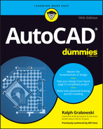
Join
Use the Join command to fill gaps between lines, arcs, elliptical arcs, open splines, 2D and 3D polylines, and helixes. If the lines are collinear (they lie in the same straight line) or the arcs, splines, polylines, or elliptical arcs are on a similarly curved path, then Join creates a single new entity to replace the existing separate pieces, as shown in Figure 11-9.
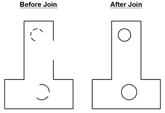
FIGURE 11-9: Joining sundered pieces.
Objects to be joined must be collinear or else their ends must be coincident. You can’t join noncollinear objects that have gaps between them or that cross or overlap.
The following steps describe how to use the Join command:
 Click the Modify panel title at the bottom edge of the Ribbon’s Home tab to open the Modify panel’s slideout, and then click the Join button.
When you foresee doing a lot of joinery, you can pin open the slideout. See Figure 11-9. AutoCAD prompts you to select the source object.
Select the source object — that is, the object you want to join other objects to.
AutoCAD prompts you according to the object type you selected. If you select a line, then the command line or Dynamic Input tooltip shows this message:
Select source object or multiple objects to join at once:Select valid objects to join to the original source object.
For example, when you selected a line as the source object, AutoCAD continues prompting for additional adjoining lines until you press Enter to end the object selection.
Press Enter to end the command.
AutoCAD joins the selected objects into a single object. The new object inherits relevant properties, such as the layer or linetype of the first object selected.
You aren’t limited to selecting a single object at the first prompt. If you select multiple objects by using windowing, then Join joins whatever objects it can and rejects those that it can’t.
You can turn an arc into a circle or an elliptical arc into a full ellipse with Join’s cLose option.
Other editing commands
![]() The REVERSE command provides an easy way to reverse the direction of lines, polylines, splines, and helixes. Why does that matter? Well, most of the time it doesn’t, but if you happen to be using a complex linetype that uses text or a directional arrow block, then you probably want the text to read right way up and the arrow to point in the correct direction. Lines, polylines, and other entity types have start points and endpoints and, therefore, a direction that runs from the former to the latter. Rather than redraw linework so that the text or symbols appear the right way up, use the REVERSE command to flip the start points and endpoints.
The REVERSE command provides an easy way to reverse the direction of lines, polylines, splines, and helixes. Why does that matter? Well, most of the time it doesn’t, but if you happen to be using a complex linetype that uses text or a directional arrow block, then you probably want the text to read right way up and the arrow to point in the correct direction. Lines, polylines, and other entity types have start points and endpoints and, therefore, a direction that runs from the former to the latter. Rather than redraw linework so that the text or symbols appear the right way up, use the REVERSE command to flip the start points and endpoints.
This command also reverses variable-width polylines. The system variable PLINEREVERSEWIDTHS controls how REVERSE handles them. When set to the default of 0 (zero), REVERSE reverses the start and end sequence but doesn’t affect the width; when set to 1, the start and end widths of segments are also reversed.
![]() The Delete Duplicate Objects tool (also known as the OVERKILL command) looks for fully or partially overlapping objects, and either combines or deletes them. Overlapping objects, such as one line partially or completely on top of or beneath another line, can mess up editing and other commands.
The Delete Duplicate Objects tool (also known as the OVERKILL command) looks for fully or partially overlapping objects, and either combines or deletes them. Overlapping objects, such as one line partially or completely on top of or beneath another line, can mess up editing and other commands.
![]() The PEdit (Polyline Edit) command can perform a great many operations on polylines. The operations fall into two categories:
The PEdit (Polyline Edit) command can perform a great many operations on polylines. The operations fall into two categories:
- They affect the entire polyline, such as its width, how curves are fitted and unfitted, reversing its direction, and defining how noncontinuous line types behave at vertices.
- They affect the polyline at specific vertices, such as setting the start and ending width of individual segments.
PEdit can also be used to turn a regular line into a single-segment polyline, and to join additional line and arc segments to an existing polyline as new segments. Check the Help facility for additional information.
Getting a Grip
At the beginning of this chapter, I say that I cover only verb-noun editing. Grip editing, however, is — by its nature — noun-verb. You grab the selected object and then perform an action on it.
Grips are little square, rectangular, or other shaped handles that appears on objects after you select them. The shape of the grip indicates its function. In its simplest guise, the square, you can simply click on one of the grips displayed by an object, and then drag the grip to a new location. The object tags along, but how it does so depends on which grip you select — sometimes the object moves, sometimes it stretches.
For lines you can
- Drag one end of a line to change the line’s length and ending position.
- Drag the midline grip to move a line without changing its length or angle.
For arcs and circles you can
- Drag the center of an arc or circle to a new location.
- Drag the diameter of a circle to a new size.
- Drag either end of an arc to a new location.
- Drag an arc to a new radius.
For more sophisticated operations, you can
- Type in a coordinate pair to specify the new location.
- Use direct distance entry (DDE, discussed in Chapter 8) to specify the distance and direction of the change.
- Use object snaps to existing objects to specify the new location. You can drag one grip until it’s close to a grip on another object and snaps to it, even when object snap modes are turned off. Figure 11-10 shows a hot (red) endpoint grip of a line being connected to the endpoint grip of another line. The angled line shows the original position of the line being edited, and the thin vertical line shows the new position. Using a grip in this way as a visible object snap offers the same advantage as using Object Snap overrides (as described in Chapter 7): It ensures precision by making objects meet exactly.
- Select multiple objects. Hold down the Shift key while selecting multiple grips. Each one turns red to indicate that it’s hot. When you move one grip, all the hot ones move in parallel with the selected one, as shown in Figure 11-11.
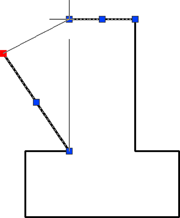
FIGURE 11-10: Using grips to connect two objects.
FIGURE 11-11: Stretching multiple objects with multiple hot grips.
Select one or more objects to activate the grips, and then click a grip. Now take a look at the command line, which displays:
** STRETCH **
Specify stretch point or [Base point Copy Undo eXit]:
So far, so good. As you move the cursor, AutoCAD displays a ghost image to show you what would happen if you were to click at that moment.
Before you click, however, press the spacebar several times and note the changes to the command line and to the ghost image. The command line scrolls through the full rotation of choices:
** STRETCH **
Specify stretch point or [Base point Copy Undo eXit ]:
** MOVE **
Specify move point or [Base point Copy Undo eXit ]:
** ROTATE **
Specify rotation angle or [Base point Copy Undo Reference eXit]:
** SCALE **
Specify scale factor or [Base point Copy Undo Reference eXit]:
** MIRROR **
Specify second point or [Base point Copy Undo eXit]:
That’s right: The six most-often-used editing options become available in rotation. Wait a minute — only five are in the list! COpy is there, but shown as an option for all of the other five.
Some grips on lines, arcs, and elliptical arcs are multifunctional. Hovering over an endpoint grip displays a pop-up menu that offers you a choice of lengthening or stretching the object.
Hovering over the midpoint grip on an arc offers the choice of stretching the arc by its midpoint (that is, keeping the same endpoints) or changing its radius.
Elliptical arcs display triangular grips at their endpoints that let you increase the length of the arc without changing its other parameters.
Hovering over a rectangular grip on the midpoint of a polyline segment offers the choice of stretching (that is, moving the current segment while maintaining its connections to its siblings), adding a new vertex (that is, splitting the current segment in two), or converting a line segment into an arc (or vice versa).
When Editing Goes Bad
Analysis of AutoCAD users’ actions suggests that one of the most commonly used functions is undo. It comes in several forms and depths of action. If you’re the impatient type, then you can jump ahead to the last two items in this list because they’ll probably account for the majority of your undo actions:
- OOPS: The OOPS command un-erases the last set of erased objects, even when other editing or drawing actions have taken place in between. This command has no menu option or Ribbon icon, so you have to type it at the command line.
- UNDO: The UNDO command is quite versatile and powerful, with several options. Among other things, you can have it undo a specified number of actions, or drop a marker flag and then undo as far back as the marker flag. See the Help facility for more information. You need to type this command on the command line because the only menu option is the typical Windows undo arrow on the Quick Access menu, which undoes just one step and doesn’t prompt for the other options.
- U: This command is available in two forms:
- Type it as a command. It undoes your last action, and you can use it repeatedly to step back through the current editing session. Just press Enter until you back up to the step you need.
- Enter it as a prompt during a number of other commands, such as Line, PLine, and COpy. In this case, it undoes the last line or polyline segment, or the last objects to be copied — but then the parent command resumes, and you can continue drawing or placing copies.
- REDO: This command reverses the last U or UNDO operation. To make REDO work, you must use it immediately after one of these operations. It appears as the typical Windows redo arrow on the Quick Access menu.
- DOO-DOO: Or words to that effect. This isn’t a command — instead, it’s what you say when you undo too many steps and then realize, to your horror, that REDO can only redo the last Undo step.
- MREDO: This command reverses multiple Undo actions and pretty much eliminates the need for DOO-DOO. It has several advanced options, though the prompts are self-explanatory.
- BAK: This isn’t a command — it’s a file type. Whenever you save your work in process, AutoCAD creates a file with the extension
.bakthat stores your drawing the way it looked immediately after the previous save operation. You can go back to this version by simply using Windows Explorer to rename the BAK file to one with the.dwgextension. - SV$: This one is also a file type. As you work, AutoCAD automatically saves a copy of your drawing every ten minutes and gives it the
.sv$file extension. You can go back to this version by simply using Windows Explorer to rename the SV$ file to one with the.dwgextension. You’ll find your SY$ files in thec:Users<login name>appdatalocal empfolder, but you can use the Files tab of the OPtions command to store them in any location you like — as well as change the duration between automatic saves.  Undo button: It invokes the UNDO 1 command and option. The Quick Access menu includes an Undo button, just as many Windows applications do.
 Redo button: It invokes the MREDO 1 command and option. The Quick Access menu includes a Redo button, just like many Windows applications do.
Don’t you just wish that the real world had Undo and Redo buttons?
Dare to Compare
In my engineering classes, I teach a session on document control wherein I emphasize the absolute importance of properly controlling and recording design revisions. Any change, no matter how minor, must be properly recorded. Otherwise, you could have two drawings that say they have the same revision number but are slightly different. You could end up with 52,473 parts that don’t quite fit — and you don’t want to know how I know that number.
![]() Just in case someone else sends you a suspect drawing file, AutoCAD 2019 introduced the new COMPARE command. It can be started from the big red A (Application) menu’s Drawing Utilities, or from the Collaborate tab on the Ribbon menu. It asks you for a drawing to compare with the current one. It then displays something like Figure 11-12.
Just in case someone else sends you a suspect drawing file, AutoCAD 2019 introduced the new COMPARE command. It can be started from the big red A (Application) menu’s Drawing Utilities, or from the Collaborate tab on the Ribbon menu. It asks you for a drawing to compare with the current one. It then displays something like Figure 11-12.
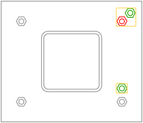
FIGURE 11-12: What’s the difference?
In the drawings that I COMPAREd in Figure 11-12, I moved the objects in the upper-right corner and copied the objects in the lower-right corner. The result of a COMPARE operation changes the colors of objects:
- Everything that exists only in the first drawing is red.
- Everything that exists only in the second drawing is green.
- Everything that is exactly identical in both drawings is gray.
Orange revision clouds are placed around the differences. The clouds have a small arc size, so you may have to zoom in to see the arc segments.
AutoCAD 2020 added more functionality. For example, you can import and export changes and differences and you can save a snapshot drawing of the comparison. AutoCAD 2022 added a DWG Compare palette that lets you walk through the differences in the two drawings, one difference at a time, by clicking the forwards and backwards arrows.
The COMPARE functionality could be useful for comparing original design drawings to “as built” revisions returned from the field.