Chapter 12
Planning for Paper
IN THIS CHAPTER
![]() Setting up paper space layouts
Setting up paper space layouts
![]() Looking into viewports
Looking into viewports
![]() Examining details at other scales
Examining details at other scales
![]() Working in paper space
Working in paper space
Most of this book revolves around setting up and using the model space environment that is infinitely large (or at least 1099 units across), a three-dimensional realm in which you create your gleaming towers, tomorrow’s wondrous electronic gadgetry — or everyday garden sheds, angle brackets, and doorknobs. You may, however, have picked up a hint here and there that AutoCAD has a whole different parallel universe available to you, known as paper space.
The final product of all this setup, remember, is a printed drawing on a piece of paper or in a digital format, such as PDF. In most industries, paper drawings are legal contract documents, so they need to be easy to read and understand. In the first part of the documentation process, you configure the layout of the sheet in paper space, which I explain in this chapter. For the actual process of outputting either model space or paper space layouts to a printer or a file, see Chapter 16.
Chapter 2 introduces you to the two parallel universes of model space and paper space, and Chapter 4 explains how to configure model space for efficient drawing. This chapter explains how to set up layouts in paper space for efficient plotting.
 Model space is the drawing environment that’s current when the Model tab (not the Model button on the status bar) is active. In model space, you create the “real” objects you’re drawing, so these objects are referred to as model geometry, whether they’re 2D objects or 3D. When the Model tab is active, you see only objects in model space. Anything in paper space is invisible.
Imagine that your screen is displaying your drawing in model space. Now place a sheet of paper in front of your monitor and cut a square hole in it so you can look through it to see all or part of the object's model space. This is like a one-way mirror; you can look through this paper space viewport to see model space, but model space can’t look back at you through the hole. You must have at least one paper space viewport in each layout to display anything from model space.
To see what I mean, try this:
Start a new, blank drawing.
By default, it starts in model space.
- Draw several random lines.
Click the Layout1 tab in the lower-left corner of the screen.
AutoCAD switches to the default layout, which has one viewport into model space. All the lines you just drew fit into the central, rectangular viewport.
- Draw a circle in the central, rectangular viewport.
Click the Model tab in the lower-left corner of the screen.
Hey, where did the circle go?
- While you're here, draw an ellipse in the general area of the lines.
Click the Layout1 tab.
Like magic, the ellipse appears and the circle reappears.
That’s the basic principle of paper space layouts. Everything you draw in model space can be seen from paper space layouts, but nothing you draw in paper space layouts can be seen when you are in model space. This feature is particularly useful for drawing the borders and title blocks in paper space that you need when you plot a drawing, but would only get in the way in model space.
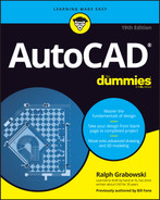
Figure 12-1 shows the arrangement of a default layout tab. It contains the following items:
- The large white rectangular area represents the sheet of paper on which the drawing will be printed.
- The dashed rectangle shows the margin (or boundary) of the actual area which the current printer can print. Anything drawn outside this margin won’t print; the margin varies with every printer model.
- The inner rectangle shows one viewport through to model space, which is displaying the grid. There can be more than one viewport, they can be any shape, and they can be located anywhere in paper space.
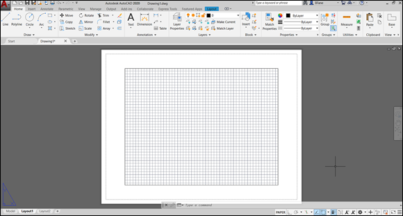
FIGURE 12-1: All spaced out.
I turned on the grid when I did the screen capture to emphasize the fact that it's in model space. As explained in Chapter 3, the grid can be turned on or off, and is never printed.
An AutoCAD drawing file always contains one and only one model space, but paper space can include more than one layout. For example, a complex drawing might have one layout for a general overview and several other layouts for larger-scale detail views. Each layout can then be plotted on its own sheet of paper. When the model space drawing is edited, all layouts immediately show the changes automatically.
Best practice these days is to draw the real stuff, such as the building, the machine, or the doorknob, in model space and paper-oriented stuff, such as the border, the title block, the view labels, and general notes, in a paper space layout.
As I point out in a number of places in this book, the sacred mantra is “always draw everything full size.” The use of paper space layouts greatly simplifies this process. As discussed a little later in this chapter, you can define the scale factor for each viewport, as well as the size of the physical sheet of paper that your printer or plotter produces. Now you can simply plot every paper-space layout as full size and everything will fit.
 In AutoCAD, you can ignore paper space layouts entirely and do all your drawing and plotting in model space. Originally, AutoCAD only had model space, with paper space added to AutoCAD in 1990. But you owe it to yourself to give layouts a try. You’ll find that they make plotting more consistent and predictable and they give you more plotting flexibility because each layout can be assigned to a different printer, if need be. You’ll certainly encounter drawings that use paper space exclusively, so you should understand both systems.
Setting Up a Layout in Paper Space
Aside from arranging drawing sheets, layouts store plot information. AutoCAD can save several separate plot settings with each layout, as well as for model space, so that you can quickly produce different types of plots for each one, without first having to set things up. For example, with one layout you can do quick check plots to a letter-size monochrome laser printer; with a second layout, you can do full-size final plots to a large-format color plotter. In practice, you’ll probably use only one paper space layout tab most of the time, especially when you’re getting started with AutoCAD.
The layout two-step
Setting up a layout is a two-step process. The first step is to define the paper, and the second step is to define the viewport or viewports.
Pick a paper, any paper
Defining the paper is a simple process. Follow these steps:
- Click the desired layout tab.
Click the Layout tab of the Ribbon menu.
The blue Layout tab is available on the Ribbon only when AutoCAD is in layout mode.
 In the Layout panel, click Page Setup.
The PAGESETUP command starts, and displays the Page Setup Manager dialog box.
Click New.
The New Page Setup dialog box appears.
Type a suitable name and click OK.
Next up is the Page Setup dialog box. This dialog box looks remarkably like the Plot dialog box that I discuss in Chapter 16.
Specify the printer you want to use, its paper size, and so on (as per Chapter 16), but leave the Plot Area drop-down list set at Layout.
Many of the names in the Printer/Plotter Name list should look familiar because they’re the Windows printers (system printers, in AutoCAD lingo). Names with the
.pc3extension represent nonsystem printer drivers. See Chapter 16 for details.Click OK.
The Page Setup dialog box closes, and the New Page Setup dialog box returns.
- Click Close to apply your new setup to the current layout.
You can repeat the page setup as often as you like in one drawing. You thus can have multiple layouts or multiple page setups, or both in one drawing. Each layout can have a different page setup, and you can use the PAGESETUP command at any time to switch a given layout to a different setup.
View that port
Now that you've set up the paper properly, it’s time to move on to the viewport setup. By default, AutoCAD starts a new drawing with a single viewport each of Layout1 and Layout2, and each viewport has a border that's on layer 0 (zero). A single viewport in a single layout is often appropriate for most drawings. You can add more layouts to the drawing, and each layout can have many viewports.
A viewport border is an actual drawing object. As such, you can move, copy, grip-edit, print, hide, and delete it, and change its properties. You can even use it as the boundary for cross-hatching, but I’m not sure why you would want to.
The default settings are probably not optimal for your needs, so you should follow these steps:
Set the layer.
A viewport boundary is a drawing object and so it will print, which you usually don’t want. Using Layer Properties Manager, create a new layer, perhaps called VPORTS, and turn off plotting for this new layer. You may also want to change the layer color or line type or both so you can easily identify viewports in drawings. I cover layers in Chapter 9.
Click the viewport object, and then click your VPORTS layer name in the drop-down list below Layers in the Layers panel of the Home tab.
The viewport object remains visible, but now it won’t plot.
Set the viewport scale.
When you did the simple exercise near the beginning of this chapter, did you notice that the first time you clicked the Layout 1 tab, everything you drew in model space just happened to exactly fit within the viewport? To make this happen, AutoCAD automatically adjusted the viewport scale factor. The problem is that it almost never turns out to be a standard scale that anyone would use. For example, when I did the exercise, the scale factor turned out to be 0.11036728. A more logical scale would be 0.1, or 1:10. No problem:
- Click the viewport boundary.
 Click the Viewport Scale button, which appears near the right end of the status bar.
- Select a suitable scale from the list of standard scales that appears. The list shows every drawing scale registered in the scales list, including metric scales, even if you’re working in a drawing using English units and vice versa.
Most of the time, way too many scales are shown in the list you see in the Viewport Scale button and in the Plot dialog box. AutoCAD has a handy-dandy Edit Drawing Scales dialog box that lets you remove imperial scales if you never work with feet and inches, and vice versa if you never work in metric. To run through the scales, choose Scale List from the Annotation Scaling panel on the Annotate tab, or type SCALELISTEDIT and press Enter to open the Edit Drawing Scales dialog box. If (okay — when) you make a mistake, click the Add button in the Edit Drawing Scales dialog box to add a lost scale factor, or click the Reset button to restore all default scales. Lock the viewport scale.
When a viewport is selected, a padlock icon appears to the left of the Viewport Scale button. The icon is a toggle that turns viewport scale locking on or off.
 Always lock the viewport scale immediately after setting it. You’ll see why later in this chapter when I discuss details at different scales.
Practice playing with the paper space and model space layouts in AutoCAD’s sample drawings. I don’t cover sheet sets in this book, but the individual drawings in the sheet sets all use paper space layouts along with model space. For example, from AutoCAD’s Start screen, click the arrow next to Open, and then select Explore Sample Drawings. When the file dialog box opens, click Sheet Sets, and then click Civil, and then click Site Grading Plan. Click Yes in the alert box that appears to see a drawing that has four paper space layouts to print four views of the model space drawing.
Put it on my tabs
The Autodesk documentation sometimes refers to the Model tab or to layout tabs, as I sometimes do. Out of the box, AutoCAD displays selectable tabs at the lower-left edge of the drawing window, clearly labeled Model, Layout1, and Layout2. Hovering your cursor over a tab pops up a preview of its contents. You can jump to a desired view just by clicking its preview image.
AutoCAD 2014 added file tabs at the top left of the graphic screen for each open drawing. Hovering the cursor over a file tab also produces quick views of model space and all layouts in the drawing. Figure 12-2 shows a typical arrangement in which AutoCAD has several drawings open. When you hover the cursor over the current file tab, a blue border indicates the currently active view. You can jump from view to view in a drawing or directly to a desired view in a different drawing just by clicking its preview image.
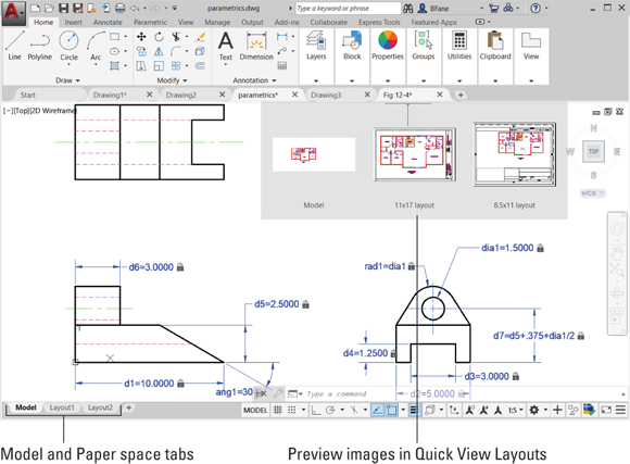
FIGURE 12-2: View those layouts, and make it quick!
You can rename a layout tab (but not the Model tab) by double-clicking the layout name and typing a new one.
Any Old Viewport in a Layout
 The viewports I talk about in this chapter are paper space viewports. You can also create viewports in model space, but they’re a completely different animal. Model space viewports are also known as tiled viewports because (like bathroom tiles) they can’t overlap. You can use tiled viewports to take a close look at widely separated areas of the screen or different viewports of a 3D model. I cover tiled model space viewports in Chapter 22 when I discuss 3D modeling. The potentially confusing aspect is that AutoCAD uses the same command name, and even the same dialog box, for creating the two different types of viewports. In this chapter, ensure that you’re in paper space when you create viewports.
Up and down the detail viewport scales
Paper space viewports are assigned drawing scales, and you can have multiple viewports, each with a different scale, all in the same layout. For example, one viewport can show the layout of a machine at 1:20, and another viewport can show an enlarged view of a small detail at 1:2. Because the individual viewports are scaled, the entire layout can be plotted at 1:1. Try the following steps:
On the Ribbon, click the Layout tab; then in the Layout Viewports panel, choose Rectangular.
If the Rectangular button is grayed out (I know, they’re all rectangular — it’s the one that is labeled Rectangular), you’re still in model space. Switch to paper space.AutoCAD prompts you to pick the first corner of the new viewport.
Pick a point somewhere on the layout page to locate the first corner of the new viewport.
AutoCAD prompts you to pick the second corner.
Pick another point to place the second corner of the new viewport.
AutoCAD draws the viewport, and the model space geometry appears inside it.
Unlike tiled model space viewports, paper space layouts can overlap each other or have spaces between them.Zoom and pan until the new viewport shows the desired region of model space.
When you zoom and pan in paper space, you simply zoom and pan the entire layout. If you zoom and pan in model space, it has no effect on the paper space viewport.
Okay, here’s the clever part. While you’re in paper space, double-click inside the viewport. You have now reached through the hole in the time-space continuum and are working in the parallel universe of model space. Any panning and zooming you do here does affect what’s visible in the layout viewport. While you're in the parallel universe, you may want to look for your missing left socks. When things are to your liking, return to the current layout by double-clicking anywhere in paper space outside the viewport.Click the viewport boundary to which you want to apply a scale.
The Viewport Scale button appears toward the right end of the status bar.
Find the scale that you want to apply to the active viewport, and then select it from the list.
The display zooms in or out automatically to adjust to the chosen viewport scale.
Lock the viewport when the scale is correct.
Click the padlock icon, which appears to the left of the Viewport Scale button near the left end of the status bar, to toggle viewport scale locking on or off.
Okay, here’s the warning I warned you about earlier in the chapter. When you don’t lock the viewport scale, others (not you, of course) can mess up the viewport scale factor in all innocence, thinking they're just zooming in for a closer look.
You can zoom directly to an exact scale factor while reaching into model space through a viewport. Start the Zoom command, and then enter the desired scale factor immediately followed by the letters XP (“times paper,” not case sensitive). For example, Z 2XP will zoom in 2:1 relative to paper scale, and Z .5XP will zoom out 1:2. Now return to paper space and lock the viewport.
When a viewport is locked, you can still double-click in it to enter model space and create or edit objects that are visible in the viewport. Panning and zooming do not affect what appears in the viewport but do affect the entire layout, as though you had momentarily slipped back into paper space.
Viewport boundaries have most of the properties and capabilities of other drawing objects. You can stretch, move, copy, delete, and so on, even when the viewport is locked. Grip editing, described in Chapter 11, can be particularly useful.
Earlier in this chapter, I say that viewport boundaries should normally be placed on their own non-plotting layer. That is generally true for the main viewport that shows all or most of the objects in model space. Standard practice, however, is for details at different scales to display their viewport boundaries, as shown in Figure 12-3. The solution is to create two layers for viewports, one that plots and one that doesn’t.
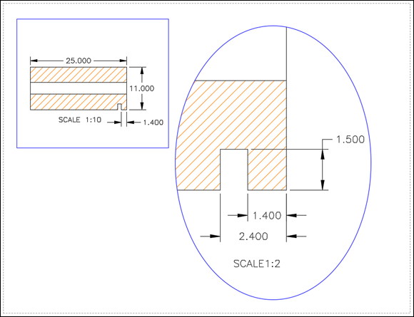
FIGURE 12-3: Show me the viewport!
Keeping track of where you’re at
When you start working in layouts, it may not always be crystal-clear whether you’re in model space or paper space. The status bar button helps because it says PAPER when you’re in paper space or MODEL when you’re in model space. You can tell the layout spaces apart in a few other ways:
- Check the cursor. If you’re in paper space, you can move the cursor over the entire drawing area. If you’re in model space by reaching through a layout viewport, you can move the cursor only in the active viewport; when you try to move the crosshair cursor outside the viewport, it turns into the Windows arrow cursor.
- Select some model geometry. Try clicking some objects that you know are in model space. If you can select and highlight them, you’re in model space. If nothing happens when you click them, they’re inaccessible because you’re in paper space.
- Check the UCS icon. The User Coordinate System (UCS) icon is the symbol at the lower-left corner of the drawing area. The model space icon shows two lines at right angles to each other, with the letters indicating the direction of the X-axis and the Y-axis. The paper space icon is triangular — its closed, three-sided shape represents a flat plane. If you don’t see this symbol, type UCSICON and press Enter, and then type either ON (to display the UCS icon in the lower-left corner of the display) or OR (to display the icon at the drawing’s origin — its 0,0 coordinates). I explain more about user coordinate systems in Chapter 8.
Practice Makes Perfect
Best practice when creating new drawings is to use paper space layouts with viewports. This greatly simplifies the drawing scale problem and related plotting issues. In particular, note the following:
- Model space:
- Here you draw everything full size.
- You must scale plots (Chapter 16), notes (Chapter 13), dimensions (Chapter 14), crosshatching (Chapter 15), and non-continuous line types (Chapter 9) separately.
- Paper space:
- Here you draw everything that isn’t part of the drawing or model, such as the drawing border, title block, and detail views.
- You configure layouts with appropriate plotter, printer, and sheet size specifications, and create appropriately scaled viewports.
- Layouts are plotted at full size (1:1).
Clever Paper Space Tricks
The following list shows a few useful tips and tricks that will help you become a paper space guru:
- Create additional layouts as necessary. You can do this in several ways, including using the New button in the Layout tab of the Ribbon menu or simply clicking the + (plus) sign to the right of the rightmost layout tab.
- Delete unused layouts. Simply right-click the undesired layout tab, and then click Delete in the context menu that appears.
- Viewports don’t have to be rectangular. The Ribbon’s Layout tab includes three options in the Layout Viewports tab, but two will be hidden under the last one used. The options are Rectangular, Polygon (you pick a series of points that lasso the desired region), and Object, which lets you choose any existing closed shape and convert it to a viewport. That’s how I created the elliptical detail in Figure 12-3.
- Freeze layers in individual viewports. You don’t always want to show everything in every viewport. If you enter model space by double-clicking inside a viewport, Layer Properties Manager (see Chapter 9) displays extra columns that let you freeze selected layers in the current viewport. Conversely, the drop-down list below the Layers panel of the Home tab includes a command to freeze the layer of the selected object in all other viewports except the current one.
- Snap into model space. Even when you are in paper space, it’s still possible to snap onto objects in model space that are visible in a viewport. This technique was used mostly before self-scaling annotations came along. Dimensions could be applied from paper space without having to worry about scaling them. The problem is that it’s usually more helpful to have the dimensions in model space when you are working there.
Use templates. Ah, now here’s the biggie. I refer to template files in several chapters, but a quick refresher wouldn’t hurt. A template file serves as the starting point for a new drawing and can contain anything that a normal drawing file can contain. This includes everything discussed in this chapter: layouts, viewports, plotting configurations, borders, title blocks, and so on. John Walker, one of the founders of Autodesk, is rumored to have once said that an AutoCAD user should never have to do anything twice. I don’t think he said it again.
But wait! There’s more! A bit of exploring will reveal that the commands for creating and configuring layouts and viewports all have a From Template option. You can browse through the current drawing and through any existing drawing or template file anywhere to inhale the complete layout setup specifications. Complete means everything; for example, when you're setting up a layout from a template and the source includes viewports, a border, and a title block, it all comes over to the new layout, including the creation of any new layer, text, and dimension specifications and block definitions required.
If the current drawing contains any specifications with the same names as the source, the host drawing wins and the incoming specifications are ignored. The existing specifications will be applied to the incoming objects.