Chapter 14
Entering New Dimensions
IN THIS CHAPTER
![]() Placing dimensions in drawings
Placing dimensions in drawings
![]() Choosing a dimensioning method
Choosing a dimensioning method
![]() Creating and modifying your own dimension styles
Creating and modifying your own dimension styles
![]() Adjusting dimension sizes to suit the drawing plot scale
Adjusting dimension sizes to suit the drawing plot scale
![]() Placing and modifying annotative dimensions, including details at other scales
Placing and modifying annotative dimensions, including details at other scales
![]() Modifying dimensions
Modifying dimensions
In drafting, whether CAD or manual, dimensions clearly indicate the size of things. They are special text labels with attached lines that point to what is being dimensioned. Although it’s theoretically possible to draw all the pieces of a dimension by using AutoCAD commands such as Line and mText, dimensioning is such a common drafting task that AutoCAD provides specific commands to do the job efficiently. These dimensioning commands place all parts of a dimension into a convenient, easy-to-edit package, much like a block. In fact, AutoCAD actually produces each dimension as something it calls an anonymous block.
Even better, as you edit an object, such as stretch a line, AutoCAD automatically updates the measurement displayed in the dimension text label to indicate the object’s new size. And perhaps best of all, AutoCAD’s annotative dimensions adjust their text height and arrowhead size automatically to suit the annotation scale on the Model tab or the viewport scale in a layout. I explain the general principles of annotative objects in Chapters 13 and 15. In this chapter, I take a close look at annotative dimensions.
Adding Dimensions to a Drawing
I start off with an exercise to introduce AutoCAD’s dimensioning function by creating linear dimensions that show the horizontal or vertical distance between two points:
Start a new drawing, using the
acad.dwttemplate file.This step creates a drawing that uses imperial units, even if your default installation uses metric. It saves lazy writers from having to duplicate instructions for metric users.
Use the Line command to draw a non-orthogonal line.
A non-orthogonal line is a segment that’s neither horizontal nor vertical. Make the line about 6 units long, at an angle of about 30 degrees upward to the right.
Set a layer that’s appropriate for dimensions as current.
Okay, you started from a blank template, so it doesn’t have specific layers, but I included this step as a gentle reminder. As I discuss in Chapter 9, you normally set dedicated layers for visible edges, hidden edges, text, dimensions, section lines, hatching, and so on.
 AutoCAD 2022 added a significant enhancement to dimensioning. A single command, DIM, handles all dimension types. The older method of using specific commands for designated dimension types is still available, and I discuss it later in “Dimensioning the Legacy Way.” As of AutoCAD 2016, you can define an override layer on which all dimensions automatically end up. See the “And the Correct Layer Is …” section at the end of this chapter.
 Start the DIM command by clicking the big DIM button on the Annotate tab’s Dimensions panel, or type DIM and press Enter.
The DIM command has nothing to do with brightness. It can replace five older dimension commands, resulting in the same dimensions but with a lot less effort: DImLinear, DimALigned, DimANgle, DimDIameter, and DimRAdius. I talk about these individual dimensioning commands in “Dimensioning the Legacy Way.”
Select the object you want dimensioned, in this case the line.
You can pick an entity, and AutoCAD make a best guess at what kind of dimension it should receive. Or you can specify the dimension type. See the different kinds of dimensions AutoCAD produces later in “A Field Guide to Dimensions.”
Select objects or specify first extension line origin or [Angular Baseline Continue Ordinate align Distribute Layer Undo]:At the next prompt, move the cursor around the line, and then pick a point to locate one of the extension lines.
As you move the cursor, notice that the dimension type changes. For a line, AutoCAD can dimension it with an aligned dimension (it appears parallel to the line), a horizontal dimension, or a vertical one.
Select line to specify extension lines origin:Press Enter to end the command.
AutoCAD automatically starts the DIM command again, so that you can carry on dimensioning objects in the drawing. Pressing Enter ends the command and returns you to the command prompt.
The DIM command has an additional set of characteristics to enhance your dimensioning experience:
- Unlike the older individual commands, you do not need to differentiate between picking exact start and end points as opposed to selecting an object. If you select an object such that your pick point is close to an object snap point, DIM will snap to it. But if you select an object in such a way that it doesn’t find a snap point, DIM automatically selects the picked object.
- Running object snaps won’t snap to the end of an extension line that is closest to the object being dimensioned. Instead, DIM snaps to the end of the dimension line itself and hence creates a continuing dimension.
- After you have placed a dimension, you don't need to restart the DIM command; it reverts to asking you to begin defining the next dimension. In this way, you can place the vast majority of dimensions in a typical drawing with just one run of the DIM command.
- While the DIM command is running, the command line shows several options that can be invoked, of which my favorite is Undo.
- To terminate the DIM command, press ESC or Enter.
Dimensioning the Legacy Way
Prior to release 2016, AutoCAD had one command for every dimensioning type. There was DimLinear for linear dimensions, DimAligned for aligned ones, and DimAngular for dimensioning angles. If you are using a version of AutoCAD older than 2016, or even if you want to apply a specify dimension type and not have AutoCAD guess at what you want, you need to use the old system. Here's how it works:
- Start the DimLInear command by clicking the Linear button at the bottom of the Annotate tab’s Dimensions panel, or type DLI and press Enter.
AutoCAD prompts you:
Specify first extension line origin or <select object>: To specify the origin of the first extension line, snap to the lower-left endpoint of the line by using an ENDpoint object snap.
If you don’t have ENDpoint as one of your current running object snaps, specify a single endpoint object snap by holding down the Shift key, right-clicking, and choosing ENDpoint from the menu that appears. See Chapter 8 for more about object snaps.
AutoCAD prompts you:
Specify second extension line origin: AutoCAD makes a link between dimensions and the objects being dimensioned. Therefore, to ensure that the values reported by dimensions are accurate and that later editing works properly, you must use object snaps or object selection when applying dimensions.
To specify the origin of the second extension line, snap to the other endpoint of the line by using the ENDpoint object snap again.
DimLInear draws a horizontal dimension (the length of the displacement in the left-to-right direction) if you move the cursor above or below the line. It draws a vertical dimension (the length of the displacement in the up-and-down direction) if you move the cursor to the left or right of the line.
AutoCAD prompts you:
Specify dimension line location or [Mtext Text Angle Horizontal Vertical Rotated]:Move the mouse to generate the type of dimension you want — horizontal or vertical — and then click wherever you want to place the dimension line.
AutoCAD draws the dimension.
 When you’re specifying the location of the dimension line, you usually don’t want to object-snap to existing objects. Rather, you want the dimension line and its text to sit in a relatively empty part of the drawing rather than have it bump into existing objects. If necessary, temporarily turn off running object snaps (for example, click the OSNAP button on the status bar) to avoid snapping the dimension line to an existing object. If you want to be able to align subsequent dimension lines easily, turn on Snap mode and set a suitable snap spacing (more easily done than said!) before you pick the point that determines the location of the dimension line. See Chapter 8 for more information about Snap mode. To automatically space several existing dimensions equally apart, you can use the DIMSPACE command.
- Repeat Steps 1–4 to create another linear dimension of the opposite orientation (vertical or horizontal).
- Click the line to select it.
Click one of the grips at an end of the line and drag it around.
The dimensions automatically update, live and in real time, to reflect the current values as you move the mouse.
You probably don’t want dimensions to display four decimal places, or maybe you want to use a different font for dimension text, or use both imperial and metric units, or show manufacturing tolerances. Not a problem! AutoCAD controls the look of dimensions by means of dimension styles, just as it controls the look of text and tables with styles. In fact, AutoCAD uses text styles also to control the appearance of text in dimensions. I cover dimension styles in greater detail later in this chapter, but suffice it to say that AutoCAD has over 80 variables that can be used to warp dimensions into just about any perversion that your industry or company can imagine.
A Field Guide to Dimensions
AutoCAD provides several types of dimensions and commands with which to draw them; most commands are shown in Figure 14-1. These commands are found on the Dimensions panel of the Annotate tab on the Ribbon. If you can’t find the button you want, it’s probably hidden in a drop-down list, under the smaller Linear button on this panel. This panel remembers the last button you used, so at any given time, it may be displaying any one of the following buttons.
You can also find these basic dimension commands in the upper-right corner of the Annotation panel of the Home tab on the Ribbon. Remember that the last one you used stays on top, so the one you want now may be underneath the one that is displayed.
In the following list, the three characters (in parentheses) is the shortened command name (command alias), which you can enter instead:
- Linear — DimLInear (DLI): Indicates the linear extent of an object or the linear distance between two points. Most linear dimensions are either horizontal or vertical, but you can draw dimensions that are rotated to other angles, too.

FIGURE 14-1: Examples of dimensioning commands.
 Aligned — DimALigned (DAL): Similar to linear dimensions, but the dimension line tilts to the same angle as a line drawn through the origin points of its extension lines. You don’t always have to pick points when placing dimensions with these commands. Watch the command line; it may ask you to
 Specify first extension line origin or <select object>:If you press Enter instead of picking the first point, AutoCAD prompts you to select an object. And when you do, it automatically selects each end of the object for you. (The DIM command reverses things: it first prompts you to pick an object.)
 Angle — DimANgle (DAN): Indicates the angular measurement between two lines, the two endpoints of an arc, or two points on a circle. The dimension line appears as an arc that indicates the sweep of the measured angle.
 Radial — DimDIameter (DDI), DimRAdius (DRA): Indicates the diameter of a circle or an arc, or a radius of a circle or an arc. You can position the dimension text inside or outside the curve; refer to Figure 14-1. When you position the text outside the curve, AutoCAD draws (by default) a little cross at the center of the circle or arc. AutoCAD automatically adds the diameter and radius symbols to the appropriate dimension type. Because radius and diameter dimensions seem to do the same thing, you might wonder when you should use which one. In most drafting disciplines, the convention is to use diameter dimensions for whole circles (for example, a hole) and use radius dimensions for part circles or arcs (for example, a fillet). You can also use DimLInear to dimension a circle or an arc. Trying to pick the endpoints of a circle can keep you busy for several hours, but if you press Enter at the first prompt and then select a circle or an arc, it applies a linear dimension across the diameter. You can also use a QUAd object snap to pick two directly opposite points on the circle.
 Arc Length — DimARc (DAR): Measures the length along an arc, and then applies a curved dimension line that’s concentric with the arc.
 Jog — DimJOgged (DJO): When dimensioning arcs, it is standard drafting practice to create a dimension line that starts at the center of the arc and proceeds outward to the arc itself. A problem arises, however, when dimensioning arcs with very large radii. The center may be at an inconvenient location and may be well beyond the edge of the final drawing. DimJOgged neatly solves this problem for you. It works almost exactly like DimARc except that it asks you to specify two extra points. After you select the arc (or circle, strangely enough), it then asks you to specify a center override point and then a location for the jog itself. The resulting dimension line consists of three segments, starting at the center override point: The first and last point to the real center; the middle segment connects the first and last points by putting a jog in the line.
 Ordinate — DimORdinate (DOR): Applies X or Y coordinate values from the origin point. Certain types of mechanical parts can have a great many holes and other features. The drawing would become impossibly cluttered if you were to apply traditional dimensions to show the X and Y locations of every detail. Common practice in this situation is to use ordinate dimensioning. Each ordinate dimension appears as a single extension line and a number showing the X or Y distance from the origin. The original is 0,0, unless a user coordinate system (UCS) is current, which is a handy way to locate the starting point for ordinate measurements. I cover UCSs in Chapter 21. Normal practice is to specify the lower-left corner of the part as the origin. The X and Y values are usually aligned neatly in a row and column along the edge of the part. There are no dimension lines or arrowheads.
- Center lines — DIMCENTER: Creates center lines or center marks on circles and arcs without applying a dimension. The definition of lines versus marks matches the current dimension style, as described later in this chapter.
Self-centered
AutoCAD 2017 introduced associative center lines. This involves two commands:
- CENTERLINES: Prompts you to select two lines. AutoCAD then draws a centerline midway between the two lines using a long-dash–short-dash line style.
- CENTERMARK: Prompts you to select a circle or an arc. AutoCAD then draws two centerlines that cross at the exact center of the circle or arc.
Now comes the magic part. Centerlines created using these two commands are fully associative to the lines, circles, or arcs that were used to define them. When you move an arc or a circle or change its radius, or when you move either the line or either end of either line, the centermarks and centerlines obediently follow and remain properly centered.
Associative centerlines are automatically placed on a layer named “Center lines” with the Center2 linetype override. If this layer doesn’t exist, AutoCAD creates it automatically with a white/black color and the Continuous linetype. If this layer already exists in your template file, AutoCAD uses the color you specified, but ignores the linetype assigned to the layer and applies the Center2 linetype override anyway.
Quick, dimension!
Three dimensioning commands can help you place multiple dimensions very quickly. They’re found near the middle of the Dimensions panel of the Annotate tab on the Ribbon.
 Continue — DimCOntinue (DCO): Having placed one linear dimension in the drawing, you can now carry on placing a series of dimensions end-to-end. AutoCAD picks the end of the previous dimension as the start of the next one automatically, so you need only locate the extension of the next one.
 Base — DimBaseline (DBA): This one works much like DimCOntinue except that AutoCAD selects the start of the previous one as the start of the next one. You thus end up with a series of stacked dimensions, all measuring from a common starting point.
 Quick Dimensions — QDIM: Interestingly, this is one of the few dimensioning commands that doesn’t start with DIMxxx. When you invoke it, it invites you to select one or more objects, and then it dimensions them all at once. The best bet usually is to use one or more window selections (pick from left to right), each of which completely surrounds several objects. Now whenever you press Enter, AutoCAD automatically applies DimLInear dimensions wherever it can, and you might be surprised at some of those places. It can place dimensions in several formats, including continue, baseline, staggered, ordinate, and several others. For convenience in repeat operations, it remembers the last mode you used.
If you want to be superefficient, memorize the three-letter command aliases for the dimension commands you use most often, of which DIM should top the list. Refer to Figure 14-1 to see the aliases of the most common commands.
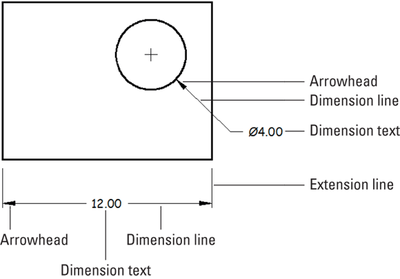
FIGURE 14-2: The parts of a dimension.
The AutoCAD dimensioning commands prompt you with useful information at the command line or at dynamic input prompts. Read the prompts during every step of the command, especially when you’re trying a dimensioning command for the first time. When all else fails …
Where, oh where, do my dimensions go?
In this section, I explain where to put dimensions, not where to place them. Huh? Right. (By now you should know to place dimensions outside the part, with smaller ones closer to the part and longer ones farther away, to avoid dimension lines crossing each other.) In this section, I show you the location in the drawing where your dimensions will live. You can choose one of three different methods for dimensioning your drawings:
- You can place dimensions in model space using non-annotative dimensions. This method, the oldest, for many years was the only possible way. I mention it here because you’re bound to encounter many of the millions and millions of existing drawings that were created this way.
- Advantage: Dimensions are available in model space as you edit the drawing.
- Disadvantage: As with text and hatching, dimension objects have to be scaled to suit the drawing scale. Placing dimensions on details at other scales can get truly ugly. I cover scale factors in Chapters 13 and 15 as well as later in this chapter.
- You can place dimensions in paper space. This was introduced as the second-generation method in an attempt to overcome the scaling issue. You can reach from paper space through a layout viewport and snap onto the model space objects. Dimensions remain associative and usually change when the model space objects change. Paper space layouts are discussed in Chapter 12.
- Advantage: You don’t need to set a dimension scale factor to suit the drawing scale. The dimension scale factor is always 1:1 because paper space layouts are usually plotted at full size, and the viewport scale sets the model space scale factor.
- Disadvantages: The dimensions aren’t available when editing in model space, so you’re flying blind. In addition, the associative connections between the paper space dimensions and the model space objects are fragile and easily broken. There’s a repair command, but it’s a nuisance to have to use it.
- You can place dimensions in model space using annotative dimensions. This is the newest, latest, greatest, and best way to place dimensions. Annotative dimensions automatically size themselves to suit the drawing scale that you choose. I discuss annotative text in Chapter 13, annotative hatching in Chapter 15, and annotative dimensions later in this chapter.
- Advantages: Dimensions are available in model space while you’re drawing and editing, you don’t need to mess with dimension scale factors, and applying dimensions to drawing details that are at a different scale from the main drawing becomes trivial.
- Disadvantage: Annotative dimensions have been slow to catch on because people are stuck in the older ways (“That’s how we’ve always done it!”) and because they don’t understand a couple of subtleties about them that I reveal in Chapter 13. If you’re the first in your office to adopt annotative dimensions, everyone else will hail you as the Great AutoCAD Guru and will pester you to help them learn how to use them.
The Latest Styles in Dimensioning
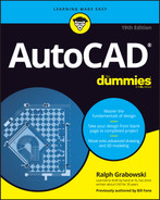
In this section, I discuss how to set the factors that control the format and appearance of dimensions, but I start with a brief anatomy lesson. AutoCAD uses the names shown in Figure 14-2, and described in the following list, to refer to the parts of each dimension:
- Dimension text: The numeric value that indicates the true distance, radius, diameter, or angle between definition points (also known as defpoints). Dimension text can include other information in addition to, or instead of, the number. For example, you can add a suffix, such as
TYP., to indicate that a dimension is typical of several similar configurations; add manufacturing tolerances; and show dual dimensioning in alternate units. - Dimension lines: In linear dimensions, indicate the true distance between points. Angular dimensions have curved dimension lines with the center of the curve at the vertex point of the objects being dimensioned. For radius and diameter dimensions, the dimension line simply points at or through the center of the object being dimensioned. Refer to Figure 14-1 for examples of these dimension types.
- Arrowheads: Appear at the end or ends of the dimension lines and emphasize the extent of the dimensioned length. AutoCAD’s default arrowhead style is the closed, filled type shown in Figure 14-2, but you can choose 20 other symbols, such as dots or tick marks, to indicate the ends of the dimension lines. Don’t get ticked off about it, but AutoCAD calls the line ending an arrowhead even when, as in the case of a tick mark, it doesn’t look like an arrow.
- Extension lines: Extend outward from the defpoints that you select to the dimension lines, usually by snapping to points on an object. By drafting convention, a small gap usually exists between the defpoint and the beginning of the extension line. Also by convention, extension lines usually extend just past the dimension lines; refer to Figure 14-2 for examples. AutoCAD makes dimensions look tidier by assigning fixed gap sizes and projection lengths for the extension lines, and if you need to dimension to circles or center lines, you can assign dash-dot linetypes to either or both extension lines.
- Definition points (or defpoints): When you create any kind of dimension, defpoints are placed on a special layer named (what else?) Defpoints. The program creates the layer automatically the first time you issue a dimension command. These tiny points are usually invisible because the objects being dimensioned sit on top of them, but you can see them by selecting a dimension to turn on its grips. The grips appear on the definition points. Because you wouldn’t want these points to appear when you plot drawings, nothing created on the Defpoints layer ever plots.
By default, no matter which type of dimension you create, AutoCAD groups all parts of each dimension (extension lines, dimension lines, arrowheads, and text) into a special associative dimension object. Associative has two meanings:
- The different parts of the dimension function as a single object. When you click any part of the dimension, AutoCAD selects all its parts.
- The dimension is connected to the points on the object that you specified when you drew the dimension. If you change the size of the object (for example, stretch a line), the dimension updates appropriately, as shown in Figure 14-3. The lines and arrows move, and the text changes to reflect the line’s new size.
 The associative dimensions I’m talking about here first appeared in AutoCAD 2002. Before that, AutoCAD had a more primitive kind of dimensioning. Dimensions were single objects, and they updated when you stretched an object if you were careful to include the dimension itself in the crossing selection for the Stretch command. Here’s where things can become confusing: AutoCAD used to call these old-style, single-object dimensions associative, but now calls them non-associative. And what used to be called non-associative dimensions before AutoCAD 2002 are now called exploded dimensions. But when you explode a dimension, you get four lines, two arrowheads, and a piece of text. Sometimes, you can’t tell the players even with a program. For more information about how to determine which kind of dimension AutoCAD draws, see the “Controlling and editing dimension associativity” section later in this chapter. I mention the old style here only because you will probably encounter it in old drawings.
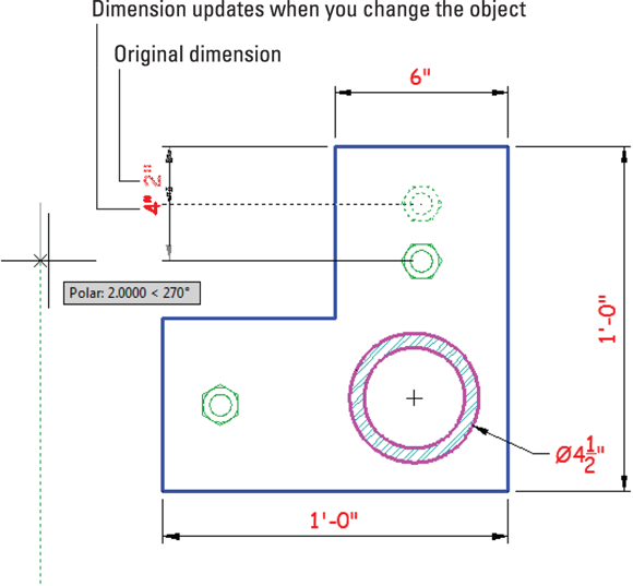
FIGURE 14-3: Changing objects automatically updates dimensions.
Some people will try to warn you that AutoCAD dimensioning is a big, complicated, difficult subject. Don’t be alarmed, however: The basic principles are quite simple. The problem is that every industry has its own dimensioning conventions, habits, and quirks. As usual, AutoCAD tries to support them all — and, in so doing, makes things cumbersome for everyone.
The good news is that you should have to adjust things to suit your specific industry or company only once, and then all dimensions will suit the specified standard. The really good news is that it usually takes only a bit of fine-tuning of the default settings to cover most of your dimensioning needs.
Dimension styles are saved in the current drawing. The really, really good news is that you can save this drawing as a template file (I cover templates in Chapter 4) so that all new drawings created from this template will have the dimension styles predefined. Or if you’re working in an office, then someone may already have set up suitable dimension styles. Or you can use DesignCenter to copy styles from one drawing to another.
You add dimensions to a drawing after you’ve drawn at least some of the geometry; otherwise, you won’t have much to dimension! (Well, duh.) Your dimensioning and overall drafting efficiency improve if you add dimensions in batches: First draw all geometry and then place dimensions. Don’t draw a line, place a dimension, draw another line, place another dimension… .
Creating dimension styles
A dimension style (or dimstyle, for short) is a collection of drawing settings, called dimension variables (or dimvars, for short), which are a special class of the system variables that I describe in Chapter 23.
![]() If you do need to create your own dimension styles or you want to tweak existing ones, use the Dimstyle command. You can invoke it by clicking the small, diagonal arrow in the lower-right corner of the Dimensions panel of the Annotate tab on the Ribbon. The Dimension Style Manager dialog box opens, as shown in Figure 14-4.
If you do need to create your own dimension styles or you want to tweak existing ones, use the Dimstyle command. You can invoke it by clicking the small, diagonal arrow in the lower-right corner of the Dimensions panel of the Annotate tab on the Ribbon. The Dimension Style Manager dialog box opens, as shown in Figure 14-4.
FIGURE 14-4: Yet another manager, this one for dimension styles.
Every drawing comes with a default dimension style named Standard when you start with an imperial (feet-and-inches) template, or ISO-25 with a metric template, and matching annotative styles. (I cover annotative dimensions later in this chapter.) Although you can use and modify the Standard or ISO-25 style, I suggest that you leave them as they are, and create your own dimension style(s) for the settings appropriate to your work. This approach ensures that you can always use the default styles as a reference. More important, it avoids a potential conflict that can change the way your dimensions look when the current drawing is inserted into another drawing: AutoCAD refers to styles by name, so if you have two styles of the same name, one will override the other. Chapter 18 describes this potential conflict.
When you install AutoCAD, it checks with the operating system (OS) to see what country you selected when the OS was installed, and then sets its measurement system accordingly. If you’re in the United States or one of the few other countries that still use imperial units, the default dimension style is Standard; most of the rest of the world defaults to ISO-25. Canada, on the other hand, is nominally metric, but most people still use imperial. The system variable MEASUREINIT controls the default action. When set to 0 (zero), AutoCAD uses imperial units; when set to 1, metric units are used. Among other things, this setting also affects text styles (see Chapter 13), hatching (see Chapter 15), and noncontinuous line types (see Chapter 9).
Starting a new drawing from an ISO template, such as acadiso.dwt, forces everything to metric, and starting a new drawing from a non-ISO template (for example, acad.dwt) forces everything to imperial, regardless of the setting of MEASUREINIT. The system variable MEASUREMENT overrides the default for a specific drawing, but it affects only text, hatching, and noncontinuous line types.
Follow these steps to create your own dimension style(s):
 On the Ribbon’s Home tab, click the label of the Annotation panel to open the panel slideout, and then click the Dimension Style button.
Alternatively, if that just sounds like too much work, you can type D and press Enter. The Dimension Style Manager dialog box appears.
In the Styles list, select the existing dimension style whose settings you want to use as the starting point for the settings of the new style.
For example, select the default dimension style named Standard or ISO-25.
Click the New button to create a new dimension style that’s a copy of the existing style.
The Create New Dimension Style dialog box appears.
Enter a New Style Name and then select or deselect the Annotative check box. Click Continue.
Select the Annotative check box to create an annotative dimension style, or deselect it for a non-annotative style.
The New Dimension Style dialog box appears. This dialog box is virtually identical to the Modify Dimension Style dialog box, which is displayed when you edit a dimension style.
Modify dimension settings on any of the seven tabs in the New Dimension Style dialog box.
See the descriptions of these settings in the next section of this chapter.
Click OK to close the New Dimension Style dialog box.
The Dimension Style Manager dialog box reappears.
Click Close.
The Dimension Style Manager dialog box closes, and the new dimension style becomes the current dimension style that AutoCAD uses for future dimensions in this drawing.
- Draw dimensions to test the new dimension style.
Avoid using the Dimension Style’s Modify button to change existing dimension styles you didn’t create, unless you know for sure what they’re used for. When you use Modify to change a dimension style setting, all existing dimensions using that style change to reflect the revised setting. Thus, a change to one minor dimension variable can affect a large number of existing dimensions! To play it safe, rather than using the Modify button to change an existing dimension style, click the New button to create a new style, which automatically copies an existing one; then you can change the settings in the copy.
A further variation on the already convoluted dimension styles picture is that you can create dimension substyles (also called style families), which are variations of a main style that affect only a particular type of dimension, such as radial or angular. If you open the Dimension Style Manager dialog box and see names of dimension types indented beneath the main dimension style names, be aware that you’re dealing with substyles.
Adjusting style settings
After you click New or Modify in the Dimension Style Manager dialog box, AutoCAD displays a tabbed New Dimension Style dialog box or Modify Dimension Style dialog box (the two dialog boxes are identical except for their title bars) with a mind-boggling — and potentially drawing-boggling, if you’re not careful — array of settings.
Fortunately, the dimension preview that appears on all tabs — as well as on the main Dimension Style Manager dialog box — immediately shows the results of most setting changes. With the dimension preview and some trial-and-error setting changes, you can usually home in on an acceptable group of settings. For more information, use the Help feature in the dialog box: Just hover the mouse pointer over the setting that you want to know more about.
If you find the preview image hard to read in the Dimension Style Manager, New Dimension Style, or Modify Dimension Style dialog boxes, click and drag the right edge of the dialog box to increase the size of the preview image.
Before you start messing with dimension style settings, know what you want your dimensions to look like when they’re plotted. If you’re not sure how it’s done in your industry, ask others in your office or profession, or look at a plotted drawing that someone in the know represents as being a good example. A general rule, that I’ve found to be helpful in virtually all aspects of life, is to stick with the defaults unless you know specifically what you want to change and why.
The following few sections introduce you to the more important tabs in the New/Modify Dimension Style dialog boxes and highlight the most useful settings. Note that whenever you specify a distance or length setting, you should enter size you want it to be when the drawing is plotted. I discuss plotting size and scale factors in Chapters 13 (text) and 15 (hatching) and later in this chapter.
When you have everything set the way you want it, click OK to close the Modify Dimension Style dialog box, and then click Close to exit Dimension Style Manager. The new style is now current.
Following lines and arrows
The settings on the Lines tab and the Symbols and Arrows tab control the basic look and feel of all parts of your dimensions, except text.
Symbolically speaking
The settings on the Symbols and Arrows tab control the shape and appearance of arrowheads and other symbols.
A useful setting is Center Marks. Depending on which radio button you select, placing a radius or diameter dimension also identifies the center by placing a small center mark, or by placing center lines that extend just beyond the circle or arc, or none. The default is the tick mark, but I prefer the line because normal drafting practice is usually to show center lines.
Tabbing to text
Use the Text tab to control how dimension text looks, which includes the text style and height to use (see Chapter 13) and where to place the text with respect to the dimension and extension lines. In particular, note the Text Style drop-down list, which shows the text styles available in the drawing. Click the three-dot Browse button at the right end of the list to open the Text Style dialog box, and edit or create a suitable text style if one doesn’t already exist in your current drawing. The default Text Height in imperial units (0.180) is too large for most situations; set it to 1/8″, 0.125′, 3mm, or another height that makes sense.
You should define the text style for dimensions with a height of 0 (zero) in the Text Style dialog box. See Chapter 13 for more information about variable-height and fixed-height text styles. If you specify a fixed-height text style for a dimension style, the text style’s height overrides the Text Height setting in the New/Modify Dimension Style dialog boxes. Use a zero-height style to avoid the problem. A zero-height text style can be a real nuisance when placing text, which means that it’s almost mandatory to have at least two text styles defined: one for text (fixed height) and one for dimensions (zero height).
Getting fit
The Fit tab includes a bunch of options that control when and where AutoCAD shoves the dimension text when it doesn’t quite fit between the extension lines. The default settings leave AutoCAD in “maximum attempt at being helpful” mode. That is, AutoCAD moves the text, dimension lines, and arrows around automatically so that nothing overlaps. On rare occasions, AutoCAD’s guesses might be less than perfect. It’s usually easier to adjust the text placement by grip-editing the placed dimension, as I describe in the section “Editing dimension geometry,” later in this chapter, instead of messing with dimension style settings.
Even at its most helpful, AutoCAD sometimes makes a bad first guess about how you want dimension text and arrows arranged. If you’re having problems getting the look you want, flip the arrows to the other side of the dimension lines by selecting the dimension and choosing Flip Arrow from the multifunction grip on the arrow.
Most important, the Fit tab includes the Annotative check box. Using annotative dimensions, as I recommend in this chapter, makes dimensioning go a lot more smoothly!
The Use Overall Scale Of setting corresponds to the DIMSCALE system variable, and you’ll hear long-time AutoCAD drafters refer to it as such. In Chapters 13 (text) and 15 (hatching), I refer to a scale factor by which text height and hatch patterns need to be multiplied so that they plot properly. This principle also applies to dimensions: When you’re using old-style non-annotative dimensions, this is where that number goes. It resizes text height, arrowhead sizes, and gaps accordingly. When Scale Dimensions to Layout (for paper space layout dimensioning) is selected, DIMSCALE is automatically set to 0 (zero). When Annotative is selected, DIMSCALE is ignored, and a suitable scale factor is applied to each dimension when it’s created.
Using primary units
The Primary Units tab gives you highly detailed control over how AutoCAD formats the characters in the dimension text string. You usually set the unit format and precision, and maybe specify a suffix for unitless numbers, when it’s not clear from the drawing which units you’re using. You may also change the Zero Suppression settings, depending on whether you want dimension text to read 0.5000, .5000, or 0.5. “Zero Suppression!” also makes a great rallying cry for organizing your fellow AutoCAD drafters.
AutoCAD 2010 introduced an interesting tweak to dimension text: dimension subunits. If the main unit of measure on a drawing is meters, rather than have a bunch of smaller distances dimensioned as, say, 0.450, you could create a centimeter subunit so that any dimension of less than 1 meter would be shown in centimeters. I was always taught a strict drafting standard specifying that all dimensions on a drawing must be in the same units. In other words, in a drawing with meters as the dimension unit, 0.45 would be correct and 45cm would be incorrect. NASA once crashed an expensive probe on Mars because some people were using imperial units and others were using metric. Check your own office standards before incorporating this feature, which you can find on the Primary Units tab of the New/Modify Dimension Style dialog box.
Other style settings
When your work requires that you show dimensions in two different systems of measure, such as inches and millimeters, use the Alternate Units tab to turn on and control alternate units. Alternate Units display both dimensions at a time. Use 25.4 as the Multiplier for Alt Units to display millimeters alongside inches. When your work requires listing construction or manufacturing tolerances, such as 3.5 +/-0.01, use the Tolerances tab to configure the tolerance format.
![]() AutoCAD includes a separate TOLerance command that draws special symbols called geometric tolerances. If you need these symbols, you probably know it and you have my sympathies; if you’ve never heard of them, just ignore them. Search for the term Geometric Tolerance dialog box in the AutoCAD Help system for more information.
AutoCAD includes a separate TOLerance command that draws special symbols called geometric tolerances. If you need these symbols, you probably know it and you have my sympathies; if you’ve never heard of them, just ignore them. Search for the term Geometric Tolerance dialog box in the AutoCAD Help system for more information.
Changing styles
To switch to a different style, click in the dimension style window in the Dimensions panel of the Annotate tab on the Ribbon, and select a style from the drop-down list. Beginning with AutoCAD 2014, if you know the name of the style that you want to use, just begin typing it at the command line. The AutoCAD command line searches for dimension styles; when you see the one you want, just click it.
Scaling Dimensions for Output
You need to adjust the size of text and dimensions that are applied in model space to suit the final plotting scale of the drawing. By far, the best way to do this is to use annotative dimensions.
Follow these steps to use the Annotative dimension style and apply an annotative scale to a dimension:
Start a new, blank Imperial drawing.
Use the
acad.dwttemplate.- Draw a horizontal line about 20 units long.
Apply a linear dimension (DimLInear, or DLI) to the line.
Pretty hard to read, isn’t it?
Switch to the Annotative dimension style.
Find the Dimension Style drop-down list that reads
Standardin the upper-right corner of the Dimension panel of the Annotate tab on the Ribbon. Click it and then choose Annotative.Change the current drawing annotation scale.
Select the 1:5 scale from the drop-down list, under the Annotation Scale button in the lower-right corner of the application window.
Use the DIMLIN command again and place a second dimension for the line.
Ah, that’s better, and it didn’t require any esoteric calculations. You now have two dimensions that measure the length of the line, but the text and arrowheads appear at different sizes now.
![]() To avoid confusing results, which is what has turned off most users from using annotative annotations, make sure that the Automatically Add Scales button near the right end of the status bar is turned off. When Automatically Add Scales is enabled, AutoCAD updates all annotation objects that support annotative behavior when you change the current annotative scale. Having all scales attached to every annotation object is not ideal as it is much harder to control where the new scale representations appear in your drawing, especially when they might not all be needed. I discuss this topic more in Chapter 13.
To avoid confusing results, which is what has turned off most users from using annotative annotations, make sure that the Automatically Add Scales button near the right end of the status bar is turned off. When Automatically Add Scales is enabled, AutoCAD updates all annotation objects that support annotative behavior when you change the current annotative scale. Having all scales attached to every annotation object is not ideal as it is much harder to control where the new scale representations appear in your drawing, especially when they might not all be needed. I discuss this topic more in Chapter 13.
Dimensioning details at different scales is always the most difficult type of dimensioning, unless you use annotative dimensions.
Here’s the easy way to create a multiscale drawing, such as the one in Figure 14-5:
- Draw the object at full size in model space, including the small notch detail.
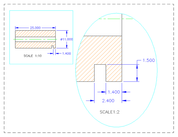
FIGURE 14-5: A drawing with a detail at another scale.
- Select the 1:10 scale from the drop-down list under the Annotation Scale button in the lower-right corner of the AutoCAD window.
Apply the three dimensions that show in the Scale 1:10 view in Figure 14-5, using an annotative dimension style.
The figure shows paper space, but you’re working in model space.
Apply an annotative hatch and then draw the center line.
Turn to Chapter 15 if you’re not sure how to apply an annotative hatch.
Edit the properties of the hatch pattern and the 1.400 dimension to add 1:2 scale factors.
Chapter 15 discusses editing hatch patterns.
Make sure that the Automatically Add Annotative Scales button is turned off, and change the Annotation Scale to 1:2.
Three existing dimensions disappear, and the hatch and the 1.400 dimension resize themselves.
- Add the 1.500 and 2.400 dimensions.
Switch to the paper space Layout1 tab. Click the viewport boundary and then grip-edit it approximately to the size and location shown.
Your model space drawing is probably not properly located, and the hatch and dimensions don’t show.
Click the viewport boundary again, click the Viewport Scale button (which might contain an AutoCAD-generated best-fit value like
0.694694), and select 1:10 from the scale list.The viewport zooms accordingly, and the hatch and 1:10 dimensions appear. If necessary, double-click in the viewport to enter model space, and then pan accordingly.
Don’t zoom or else you lose the scale setting!- Double-click outside the viewport to return to the paper space layout.
 Create a second viewport by using the VPORTS command, or simply copy it and then modify the existing one.
Repeat Steps 8 and 9 on the new viewport, but use a Viewport Scale of 1:5.
Use the Lock/Unlock button to lock the viewports to prevent inadvertently messing with them.
There you have it — a multiview, multiscale detail drawing without duplicating any geometry or annotations. To see the real magic of it, go to the model space tab and observe that there’s still only one model of the part and no detail view at the other scale. Use the Stretch command to play with the depth and location of the notch. Go back to the Layout1 tab to see how everything has automatically updated in both views. Magic!
Editing Dimensions
After you draw dimensions, you can edit the position of the various parts of each dimension and change the contents of the dimension text. AutoCAD groups all parts of a dimension into a single object.
Editing dimension geometry
The easiest way to change the location of a part of a dimension is with grip editing. I describe editing with grips in Chapter 11. Just click a dimension, click one of the grips (which generally appear at the text, the ends of the dimension lines, and the defpoints), and then maneuver away. You’ll discover that certain grips control certain directions of movement.
In AutoCAD 2012, dimensions joined the group of objects that feature multifunction grips. Hover the cursor over the text grip of a linear dimension, and notice the menu that appears, with numerous options for adjusting the location of the text. Hover over an arrow grip, and you can stretch the extension line(s) longer or shorter, start a continuous or baseline dimension from that end of the dimension, or flip the arrow. You can do these things by selecting a dimension and changing items in the Properties palette, but the multifunction grips are more immediate.
When you want to change the look of a component of a specific dimension, use the Properties palette. For example, you can substitute a different arrowhead (Arrow 1 and Arrow 2) or suppress an extension line (Ext line 1 and Ext line 2). See Chapter 11 for more on the Properties palette. All dimension settings in the New/Modify Dimension Style dialog boxes (see “Adjusting style settings,” earlier in this chapter) are available in the Properties palette after you select one or more dimensions.
Follow these tips for editing dimensions:
 Use smart breaks. In manual drafting, it’s considered bad form to cross object lines (that is, real geometry) with dimension lines or extension lines, or to have anything cross a dimension line. Extension lines can be crossed. Dimension Break (DIMBREAK) prompts you to select a dimension and then an object to break the dimension line. The wild aspect is that it’s a smart break. If you later change where they cross, the break follows accordingly — the break even heals itself when you remove the crossing elements. Better yet, if you change things again so that they cross again, the break reappears!
 Use the DIMSPACE command. The Dimension Space (DIMSPACE) command applies a specified separation between existing linear or angular dimensions. If you don’t use the DimBAseline command as the dimensions are created, spacing dimensions equally afterwards will require tedious manipulation with Snap Mode and the Move command.
You don’t always have to draw everything at full size. A fundamental mantra in AutoCAD is that you should always draw everything at full size. On occasion, however, it isn’t always practical. For example, you may design a power-transmission shaft for a large machine. The shaft is 4 inches in diameter and 12 feet long. It has a variety of splines, keyways, and bearing shoulders on each end, but the 11-foot section in the middle is simply a straight cylinder. If you draw it at full size and scale the plot to fit a suitable paper size, you’ll never see the details at each end.
 Common practice would be to draw the interesting end details, break out and remove the boring center section, and then bring the ends closer together. Now you can create a reasonable plot. The problem is that any dimension that crosses over the break, such as the overall length, doesn’t show the correct value. The solution is to override the value, and then to use the DIMJOGLINE command to insert a jog in the dimension line to indicate that the dimension line isn’t the true length. I explain how a little later in the section “Editing dimension text.” In spite of the name similarities, don’t confuse DIMJOGLINE with the DimJOgged command, covered earlier in this chapter. DIMJOGLINE is for linear dimensions, and DimJOgged is for radial dimensions.
- Right-click for useful options. If you select one or more dimensions and right-click, the menu displays a number of useful options for overriding dimension settings or assigning a different style.
Sometimes, it’s better to create a new style. When you change a setting in the Properties palette, you’re overriding the default style setting for that dimension. If you need to make the same change to a bunch of dimensions, it’s usually better to create a new dimension style and assign that style to them. You can use the Properties palette or the right-click menu to change the dimension style that’s assigned to one or more dimensions.
If you manually change a dimvar setting, the setting is applied to the current dimension style as an override, and all subsequent dimensions that are placed by using this style have the overridden appearance. This can cause much the same problem as overriding object properties instead of using different layers; if you edit a dimension style, all existing dimensions that use it update, including the ones that you hadn’t expected because they seem to be different from the ones you want.- Use a mask for the dimension text. You can use the Properties palette to turn on AutoCAD’s background mask feature (described in Chapter 13) for the text of individual dimensions: Select the dimensions, display the Text area in the Properties palette, and find the Fill Color item. Click in the list box, scroll down, and select Background to use the drawing background color, which usually gives the best results. To ensure that dimension text lies on top of other objects, use the TEXTTOFRONT (Chapter 13) or DRAWORDER (Chapter 18) commands.
- Don’t explode dimensions. The AutoCAD eXplode command on the Home tab’s Modify panel blows a dimension to smithereens — or at least into a bunch of line, polyline, and multiline text objects. Resist the temptation. Exploding a dimension makes it much harder to edit cleanly and eliminates AutoCAD’s ability to update the dimension text measurement automatically.
Editing dimension text
In most cases, you shouldn’t have to edit text in dimensions. Assuming that you draw the geometry accurately and pick the dimension points precisely, AutoCAD always displays the right measurement. When you change the size of the associated object, AutoCAD updates the dimension text. However, you may occasionally want to override the dimension text (that is, replace it with a different measurement), add a prefix or a suffix to the true measurement, or change its display accuracy.
AutoCAD creates dimension text as multiline text, so dimension text has the same editing options as mText. You have several ways to launch the dimension text editor, but the easiest is to simply double-click the dimension text.
AutoCAD displays the true dimension length as text in the actual dimension, and updates the text when you change the size or location of the object. You can override the true length by replacing it with a specific length or another text string. You can preserve the true length by adding a prefix or suffix by inserting <> (that is, the left and right angle-bracket characters) as placeholders for the dimension value. For example, if you enter About <> and the actual distance is 12.000, AutoCAD displays About 12.000 for the dimension text. If you stretch the object later so that the actual distance changes to 14.528, AutoCAD changes the dimension text automatically to read About 14.528. Now you can appreciate the importance of drawing and editing geometry precisely!
Avoid the temptation to override the default dimension text by replacing the angled brackets with a numeric value unless you plan to use the DIMBREAK command on the dimension. Doing so eliminates AutoCAD’s ability to keep dimension measurements current; even worse, you get no visual cue that the default distance has been overridden unless you edit the dimension text. If you’re overriding dimension text a lot, then it’s probably a sign that the creator of the drawing didn’t pay enough attention to using precision techniques when drawing and editing. I don’t point fingers, but you probably know whom to talk to.
Controlling and editing dimension associativity
When you add dimensions by selecting objects or by using Object Snap modes to pick points on the objects, AutoCAD normally creates associative dimensions, which are connected to the objects and move with them. This is the case in new drawings that were originally created in any release of AutoCAD starting with 2002.
When you have to work on drawings created or last edited in versions older than AutoCAD 2002, you must set the DIMASSOC system variable to 2 before later releases will create associative dimensions. An easy way to make this change for the current drawing is to open the Options dialog box (click the Application button and choose Options from the bottom of the Application menu), click the User Preferences tab, and turn on the Make New Dimensions Associative setting. Be aware that this setting affects only new dimensions that you draw from now on. To make existing non-associative dimensions associative, use the DIMREASSOCiate command described in the following list. Search for the term DIMASSOC system variable in the AutoCAD Help system for more information.
You aren’t likely to need any of these three commands often, but when you do, look up the command name in the online Help system:
- DIMREASSOCiate: If you have dimensions that aren’t currently associative (probably because they were created in older versions of AutoCAD) or they’re associated with the wrong objects, you can use the DIMREASSOCiate command to associate them with points on the objects of your choice.
- DimDisAssociate: You can use the DimDisAssociate (DDA) command to sever the connection between a dimension and its associated object.
- DIMREGEN: In a few special circumstances, AutoCAD doesn’t automatically update geometry-driven associative dimensions. In those cases, the DIMREGEN (no command alias) command fixes things.
And the Correct Layer Is …
Starting with AutoCAD 2016, you can set up AutoCAD so that dimensions are automatically placed on the correct layer. Follow these steps:
Start the LAyer command.
 Click the Layer Properties button on the Layers panel.
Create a new layer.
Give it a suitable name, such as Dims, and assign it a desired color. I discuss layers in Chapter 9.
- Click the Annotate tab of the Ribbon menu.
In the Dim Layer Override drop-down list in the middle of the Dimensions tab, select your dimension layer.
That’s it! Whenever you add a dimension to this drawing, it will automatically land on your dimension layer, regardless of which layer is active.
DO NOT use this layer selection drop-down list when you want to change the current layer for other drawing objects. This list sets only the dimension layer.
Create and set your default dimension layer in your template drawing. Any new drawings that are created from your template will automatically have your dimension layer predefined. I discuss templates in Chapter 4.