Chapter 1
Introducing AutoCAD and AutoCAD LT
IN THIS CHAPTER
![]() Launching AutoCAD
Launching AutoCAD
![]() Creating your first drawing in AutoCAD
Creating your first drawing in AutoCAD
![]() Seeing the complete picture
Seeing the complete picture
![]() Understanding the difference between pixels and vectors
Understanding the difference between pixels and vectors
![]() Comprehending the Cartesian coordinate system
Comprehending the Cartesian coordinate system
This chapter helps ease you into using AutoCAD to create engineering drawings. Although it’s not uncommon to feel overwhelmed the first time you see AutoCAD, rest assured that you don’t need to learn all the controls that you see in the default environment to be an efficient user of the program.
After a brief introduction to the program, I take you through an exercise to show you just how easy it can be to use AutoCAD. The exercise is followed up with some key concepts that you should understand when using AutoCAD, including how it differs from most other computer applications.
 When you’re starting out with AutoCAD, heed this quote from The Hitchhiker’s Guide to the Galaxy:
Don’t panic!
Launching AutoCAD
The first thing you need to do to start using AutoCAD is to launch the AutoCAD program (well, duh!) and, if necessary, maximize its screen display. AutoCAD has so many tools and palettes that you’ll almost always want to use it in full-screen mode. Follow these steps:
Launch AutoCAD.
As indicated in the Introduction, I assume that you have a working knowledge of how to use your version of Windows, including how to launch applications. Depending on your version of Windows and how it is set up, you might have to double-click a desktop icon or find a suitable entry in the Start → [All] Programs menu or Start → All Apps menu on the start screen. The wording of the selections varies depending on the version of AutoCAD and Windows.
 Start a new drawing.
Click the rectangular New button towards the upper-left corner of the screen.
If necessary, expand AutoCAD to full-screen mode.
Click the middle Windows button in the upper-right corner of the application window.
If necessary, expand the graphic area (the big, gray area in the middle) to full-screen size.
Click the middle button in the upper-right corner, near the compass rosette.
Place the cursor in the gray graphics area (midscreen), and then press the Esc key twice to make sure that no commands are active.
Now you’re ready to start drawing in AutoCAD, as shown in Figure 1-1.
Your screen may look a little different from Figure 1-1 depending on your version of AutoCAD and Windows and your screen resolution. Note too that although you'll draw using white on dark gray (refer to Figure 1-1), I drew using black on white (see Figure 1-2), and my menu icons have a white background compared to your gray background. I made the color change so that the figures would be clearer on the printed page.
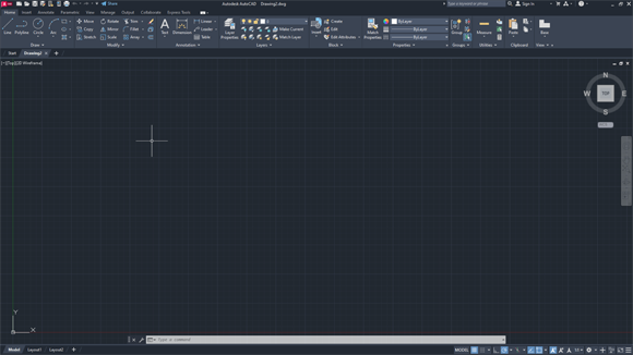
FIGURE 1-1: Your AutoCAD, ready to draw!
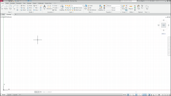
FIGURE 1-2: My AutoCAD, ready to draw!
Drawing in AutoCAD
AutoCAD offers a wide range of commands to create, modify, and annotate 2D and 3D designs. Don’t feel as though you need to learn and master every one of the approximately 1,300 (and counting) commands and options that AutoCAD offers to be a proficient drafter; most veteran drafters probably use only 20 or so commands for most basic drafting tasks.
The following simple exercise introduces a few of the commonly used commands to establish the size of your drawing area as well as the commands for creating straight line segments and circles.
You can start a command by clicking its button on the Ribbon menu, which is across the top of the screen, or by entering the command's name in the command line, which is the light-gray text-entry area at the bottom of the screen that reads Type a command.
In this exercise and others in this book, AutoCAD’s command line entries look like this, and you type the commands and responses shown in bold. Press Enter or the spacebar after each command or response that you type.
 You don’t even have to move the cursor to the command line. As you type, AutoCAD tries to guess which command you want and displays a list of possibilities at the command line, even when the cursor is on the Ribbon menu area. When you see the command you want, simply click it in the list.
 In the following exercise, don’t add spaces on either side of a comma! In most situations, AutoCAD treats pressing the spacebar the same as pressing Enter, which makes keyboard entry fast and easy but messes things up when you do it at the wrong time. In addition, make sure you use a comma as the X,Y separator and the period (.) as the decimal delimiter, and don’t use a thousands separator (,). Some parts of the world use the comma as the decimal separator and the space as the thousands delimiter, either of which confuses AutoCAD to no end.
In this first exercise I ask you to do things without explaining why. Trust me; all will become clear in later chapters:
- Set up an appropriate size for the drawing:
LIMITS
Reset Model space limits:
Specify lower left corner or [ON/OFF] <0.0000,0.0000>: 0,0
Specify upper right corner <12.0000,9.0000>: 60,40
Now, to be able to see the entire drawing area, type the letters Z A and press Enter. Note that there must be a space between the Z and the A.
- Disable Dynamic Input mode to work with the command line:
DYNMODE
Enter new value for DYNMODE <3>: -3 - Draw the frame:
Line
Specify first point: 26,12
Specify next point or [Undo]: 13,12
Specify next point or [Undo]: 22,24
Specify next point or [Close Undo]: 40.5,24
Specify next point or [Close Undo]: 41,22
Specify next point or [Close Undo]: 26,12
Specify next point or [Close Undo]: 20.6667,28
Specify next point or [Close Undo]: 25,28
Specify next point or [Close Undo]: Enter - Draw a bit more:
Line
Specify first point: 45,12
Specify next point or [Undo]: 42.87,14.53
Specify next point or [Undo]: 39.38,28.5
Specify next point or [Close Undo]: 35.3,30
Specify next point or [Close Undo]: Enter - Draw a round thing:
Circle
Specify center point for circle or [3P 2P Ttr (tan tan radius)]: 13,12
Specify radius of circle or [Diameter]: 8 - Draw another round thing:
Circle
Specify center point for circle or [3P 2P Ttr (tan tan radius)]: 45,12
Specify radius of circle or [Diameter]: 8
Figure 1-3 shows the bicycle you’ve drawn, and you didn’t even need training wheels!
It has been claimed that Line and Circle are the second- and third-most-used commands after UNDO. You should now SAVE your drawing as an historic artifact. That was easy, wasn’t it?
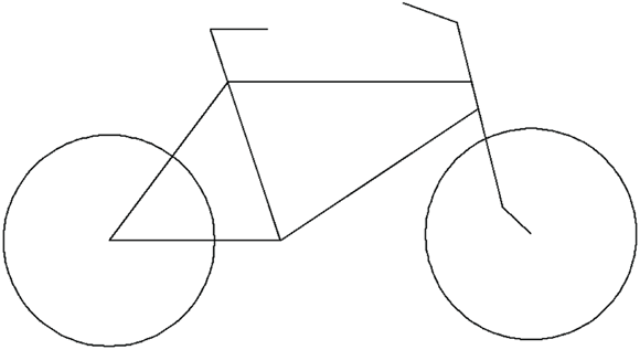
FIGURE 1-3: Your first AutoCAD drawing.
Understanding Pixels and Vectors
To use AutoCAD effectively (or even at all) you need to understand how an image is displayed on your computer screen, and how the image is stored when it is not being displayed.
- An image on a computer screen is made up of pixels. When you look closely at the screen with a strong magnifying glass, you’ll see that the image is formed from a large number of small dots of light, as shown in Figure 1-4, called pixels. This has nothing to do with Tinker Bell, except that an onscreen image of her would indeed be made up of pixels.
- All programs that display a graphic image simply turn on or off suitable spots to build the picture. This is a raster image. A straight line in a raster image is just a fortuitous alignment of appropriate dots, and after it’s been created, it can’t be edited as a single object.
- A major difference between CAD programs and computer graphics programs (such as Microsoft Paint) lies in how they save the image to disk. When the image from a Paint-type program is saved to disk, it’s stored as a bitmap that simply lists the color of each pixel. It's simply a snapshot of what you see onscreen.
- All CAD programs work with and store on a vector file on disk. A vector file is a big collection of numbers and words that list the type, size, and location of every entity in the drawing. When a CAD program displays your drawing onscreen, it analyzes the vector data and calculates which pixels to turn on or off, depending on which portion of the drawing you’re viewing. CAD programs understand that a circle is a closed curve with a center point and a constant radius. If you change its radius, the CAD program redraws the image onscreen to show the new size.
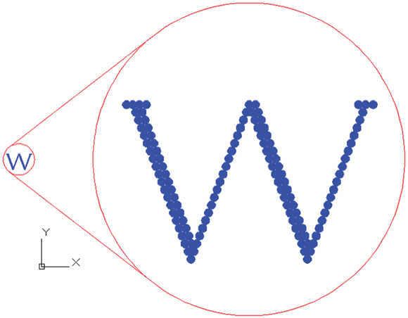
FIGURE 1-4: Pixels.
AutoCAD doesn’t limit you to working only with what you can see onscreen. You can include as much detail in a drawing as needed. You can zoom in to see more detail and zoom out to see the big picture. At any time, the screen shows only those entities and their detail that the screen is capable of showing.
Some screens can show more pixels than others can. The number ranges from the 320 per row by 200 rows (320 x 200) of the very old Color Graphics Adapter (CGA) of the 1980s to 3840 x 2160 and beyond for today’s 4K monitors. However, the drawing file always contains the same information. If it were moved to a computer with a higher resolution graphics adapter and monitor, then greater detail would show without you having to zoom in as far. Conversely, a drawing file moved to a computer with a lower screen resolution does not lose any detail, but you'll need to zoom in more closely to see details clearly.
 How big is “the big picture”? AutoCAD can draw a circle with a radius of 1099 (a 1 followed by 99 zeros) units, but the observable part of the universe is “only” about 5 x 10²³ miles in diameter, depending on how you measure and whose numbers you use (subject to change without notice). Check out
 en.wikipedia.org/wiki/Observable_universefor the latest number.Conversely, AutoCAD can draw a circle with a with a radius as small as 10-99 (which equals 0.00000[plus 90 more zeros plus]0001) units in diameter, as opposed to the classical radius of an electron, which is positively huge at 2.8179403267 x 10⁻¹³ cm.
- It’s possible for a drawing file to contain much more than you can see at any one time. The computer screen is not really the drawing; it is just a viewer that lets you look at all or part of the drawing file.
The Cartesian Coordinate System
AutoCAD uses the Cartesian coordinate system to define all locations in the drawing. This includes things such as the starting and ending points of lines, the centers of circles, the locations of text notes, and so on. Cartesian coordinates are named for French philosopher René Descartes, who is famous for statement “I think, therefore I am,” although today he might say, “I tweet, therefore I am” — although tweeting doesn’t always involve thinking.
In his Discourse on Method, Descartes, wearing his mathematician’s hat, came up with the idea of locating any point on a planar surface by measuring its distance from the intersection of a pair of axes (called, by convention, the X-axis and the Y-axis). (That’s axes as in more than one axis, not several tools for chopping wood.) By convention, the intersection of these axes are perpendicular to one another, and their intersection point is identified as 0,0 — or the origin.
For example, if your address is 625 East 18th Street in a typical town, you live 6¼ blocks east of First Avenue and 18 blocks north of Main Street.
AutoCAD also uses the notation that the origin is at point 0,0. Positive values are to the right of and above this point, and negative values are to the left of and below it. You can identify any location on a drawing by its horizontal distance from the origin, followed by its vertical distance from the same starting point.
AutoCAD shows Cartesian coordinates as a pair of numbers separated by a comma. The number to the left of the comma is the X (horizontal) coordinate, and the value to the right is the Y (vertical) coordinate. You used this convention when creating your bicycle drawing. When working in three dimensions (see Chapter 21), AutoCAD adds a third coordinate: Z.
It’s worth repeating my earlier warning: Make sure you use a comma as the X,Y separator and the period (.) as the decimal delimiter, and don’t use a thousands separator.