Chapter 2
802.11 Physical (PHY) Layer Frame Format
In this chapter, you will learn about the following:
- Physical Layer Operations
- Carrier Sense/Clear Channel Assessment(CS/CCA)
- Transmit (Tx)
- Receive (Rx)
- Physical Layer
- PLCP Service Data Unit
- PLCP Protocol Data Unit
- Physical Media Dependent
- PLCP Protocol Data Unit
- PLCP Preamble
- Long PPDU Preamble
- Short PPDU Preamble
- OFDM PLCP Preamble
- PLCP Header
- 802.11n PPDUs
- Non-HT Legacy PPDU
- HT Mixed PPDU
- HT Greenfield PPDU
- Data Field
- 2.4 GHz Communications
- 2.4 GHz Channels
- 5 GHz Communications
- UNII-1 (Lower Band)
- UNII-2 (Middle Band)
- UNII-2 Extended
- UNII-3 (Upper Band)
- 5 GHz Channels
- Adjacent, Nonadjacent, and Overlapping Channels
- Clause 14 FHSS PHY
- Hopping Sequence
- Dwell Time
- Hop Time
- Modulation
- Clause 15 DSSS PHY
- DSSS Data Encoding
- Modulation
- Clause 17 OFDM PHY
- Convolutional Coding
- Modulation
- Clause 18 HR-DSSS PHY
- Modulation
- Clause 19 ERP PHY
- Clause 20 HT PHY
This chapter will introduce you to the Physical (PHY) layer frame format. The beginning of this chapter will provide a basic overview of the PHY layer and its functions. This overview will provide a foundation that will help you understand the components of the PHY layer and how they interact. This chapter will then provide details about each of the different 802.11 PHY layer implementations that are currently defined in the standard and ratified amendments.
No matter which PHY layer implementation is being used by the wireless station to transmit or receive data, there is a functional commonality between them all. Each STA must wait and listen to see whether there is data being sent that it must receive and process, or it must wait and listen to see whether the channel is clear so that it can transmit. The details of how these tasks are performed vary between the different PHY layer implementations and are beyond the scope of what is covered in this book. The following paragraphs describe these three modes or states that an STA will transition between:
Carrier Sense/Clear Channel Assessment (CS/CCA)
If the station is not currently transmitting or receiving, it listens and senses the channel either to detect the beginning of a network signal that can be received (carrier sense) or to identify whether the channel is unused and available prior to transmitting a packet (clear channel assessment).
Essentially, either a station is transmitting or it is idle. If it is idle, it could be listening and waiting for the channel to become available so that it can transmit a frame. It could also be listening, waiting to sense the beginning of a transmission from another station, or it could be listening and receiving a frame that is being transmitted by another station. This chapter covers the PHY frame format and how the different components of the frames are used in the communications process.
Transmit (Tx)
When a station needs to transmit a frame, it must first check to see whether the wireless medium is available. This is done by the CS/CCA process. After the medium is available and it is the station’s turn to transmit, the station will transmit the frame and immediately switch back to receive mode. Since wireless stations cannot transmit and receive (or listen) at the same time, unlike Ethernet, it is not possible to listen for collisions. Therefore, after a frame is transmitted, if the frame is successfully received, the receiving station will reply to the transmitting station with an acknowledgment. The receiving station may send an acknowledgment (ACK) for a single frame or a block acknowledgment (BlockACK) for multiple frames. Both acknowledgments will be covered in chapter 5.
Receive (Rx)
If the CS/CCA identifies that the medium is busy, the station needs to be able to identify whether the medium is busy because of another device transmitting a frame. The transmitting station will precede that data portion of the frame with a preamble. This preamble contains a string of 0s and 1s that the receiving station can identify and synchronize with, essentially alerting the receiving station to the transmission. The preamble also includes a Start Frame Delimiter field, which the receiving station uses to identify the beginning of the frame. After the preamble, the length field in the frame header tells the receiving station how long the frame is. After the entire frame is received, if the frame is determined to be intact by the station it is addressed to, that station will reply to the transmitting station with an acknowledgment frame (ACK).
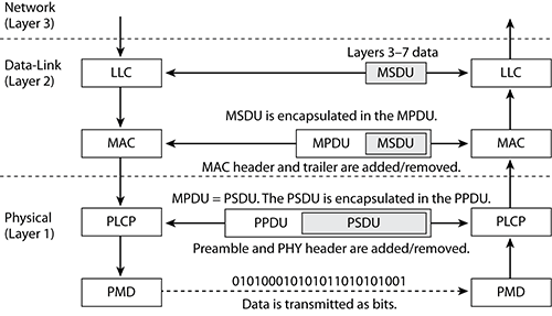
The Physical layer is divided into two sublayers. The upper portion of the Physical layer is known as the Physical Layer Convergence Procedure (PLCP) sublayer, and the lower portion is known as the Physical Medium Dependent (PMD) sublayer. The PLCP prepares the frame for transmission by taking the frame from the MAC sublayer and creating the PLCP Protocol Data Unit (PPDU). The PMD sublayer then modulates and transmits the data as bits. When the MAC Protocol Data Unit (MPDU) is handed down to the physical layer, it is then referred to as a PLCP Service Data Unit (PSDU). The PSDU is then prepared to be transported as part of a PPDU.
PLCP Service Data Unit
The PSDU is the data that the PHY transmits. The PSDU is equivalent to the MPDU that is passed down from the Data-Link layer. The PSDU and MPDU are like two sides of a door. When you are at a door, it could be the entrance or the exit. It depends on what side of the door you are on, but either way, it is the same door. The PSDU is a view of the MPDU from the other side. The MAC layer refers to the frame as the MPDU, while the Physical layer refers to this same frame as the PSDU. The difference is which side of the door you are on, or, in the OSI model, from which layer of the model you are looking at the frame.
PLCP Protocol Data Unit
When the PLCP receives the PSDU, it then prepares the PSDU to be transmitted and creates the PLCP Protocol Data Unit (PPDU). The PLCP adds a preamble and PHY header to the PSDU. The preamble is used for synchronization between transmitting and receiving 802.11 radios. When the PPDU is created, the PMD sublayer takes the PPDU and modulates the data bits and begins transmitting.
Figure 2-1 shows the upper-layer information moving between the Data-Link and Physical layers.
Figure 2-1: Data-Link and Physical layers
Physical Medium Dependent
When transmitting, the PMD receives the PPDU from the PLCP sublayer. The PMD is then responsible for transmitting the Physical layer data unit. The PMD transmits the data as RF modulated 1s and 0s. When receiving, the PMD listens to the RF, interpreting the modulated RF signal as 1s and 0s and then passing the received data up to the PLCP sublayer.
The PLCP Protocol Data Unit consists of three parts: PLCP Preamble, PLCP Header, and PSDU. When the PLCP layer receives the PSDU from the MAC layer, the appropriate PLCP Preamble and PLCP Header are added to the PSDU to create the PPDU.

Remember that the MPDU and PSDU are two names for the same thing. The MAC layer refers to the data that it passes to the Physical layer as the MPDU, while the Physical layer refers to it as the PSDU. Although this is the proper usage of these terms, they are often improperly interchanged. In fact, when referring to the different PHY implementations in the IEEE 802.11-2007 standard, one section of the standard shows the PPDU consisting of the PLCP Preamble, PLCP Header, and PSDU, while another section shows the PPDU consisting of the PLCP Preamble, PLCP Header, and MPDU.
PLCP Preamble
When transmitting data, the transmitting station alerts the receiving station of the transmission by sending a PLCP Preamble at the beginning of the transmission. The preamble is a string of 0 and 1 bits that are used to synchronize incoming transmissions. The IEEE 802.11-2007 standard defines three different preambles in the Long PPDU format, the Short PPDU format, and the OFDM PLCP preamble. The 802.11n amendment further defines three additional preambles in three different PPDUs: non-HT legacy PPDU, HT-mixed PPDU, and HT-Greenfield PPDU. The Long PLCP preamble, the Short PLCP preamble, and the OFDM PLCP preambles are described in the following sections, while the other three are discussed later in this chapter along with the rest of their PPDUs.
Long PLCP Preamble
The Long PPDU includes a 144-bit PLCP Preamble that consists of a 128-bit Sync field and a 16-bit Start of Frame Delimiter (SFD), as shown in Figure 2-2. The purpose of the Sync field is to alert the receiver that the potentially receivable signal is present. A receiver (Rx) 802.11 station will then begin to synchronize with the incoming signal after detecting the Sync field. The Sync field is then followed by the SFD field, which consists of the following 16 bits (1111 0011 1010 0000). Synchronization between the Tx and Rx must occur before the SFD field. The SFD effectively is an indicator that the information found in the PLCP Header is coming next. The Long Preamble is transmitted using Differential Binary Phase Shift Keying (DBPSK) at the rate of 1 Mbps. The modulation used for the Long Preamble is fixed. The modulation of the PLCP Header is also fixed. The modulation of the PSDU (MPDU) is not necessarily the same as that used for the preamble or the header. When the Sync field is transmitted, receiving stations may not identify it immediately. It does not matter whether the entire Sync field is received, as long as the SFD is received and identified.
Short PLCP Preamble
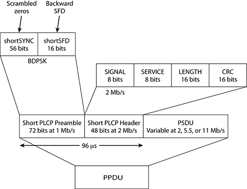
The Short PPDU includes a 72-bit PLCP Preamble, which consists of a 56-bit Sync field and a 16-bit SFD, as shown in Figure 2-3. A 72-bit preamble used for synchronization effectively has half the PHY layer overhead of the legacy 144-bit Long Preamble. The SFD field consists of the following 16 bits (0000 0101 1100 1111), which is the reverse order of the SFD used in the Long PPDU. Like the Long PLCP Preamble, the Short PLCP Preamble is transmitted using DBPSK; however, the Short PLCP Header is transmitted using 2 Mbps Differential Quadrature Phase Shift Keying (DQPSK). The modulation used for the Short Preamble is fixed. In addition to the Short Preamble having a fixed modulation, the modulation of the PLCP Header is also fixed. Once again, keep in mind that this is not the same modulation used for data bit transmission of the PSDU (MPDU).
Figure 2-2: Long PPDU format

Figure 2-3: Short PPDU format
OFDM PLCP Preamble
The OFDM PLCP Preamble, also referred to as the OFDM training structure, consists of 10 short symbols and 2 long symbols, as shown in Figure 2-4. In the figure, t1 to t10 identify the short training symbols, GI2 is a long guard interval, and T1 and T2 identify the long training symbols. Following the PLCP preamble is the SIGNAL field and the DATA fields, each with a guard interval preceding them. The total training length is 16 µs. A short OFDM training symbol consists of 12 subcarriers while a long OFDM training symbol consists of 53 subcarriers.
Figure 2-4: The OFDM training structure (PLCP Preamble)

PLCP Header
Long and Short PLCP Headers are both 48 bits long and contain the following four fields, shown earlier: Signal (8 bits), Service (8 bits), Length (16 bits), and CRC (16 bits). The purpose of the Signal field is to indicate which modulation method will be used to transmit the PSDU portion of the PPDU. Remember that a PSDU is the same thing as an 802.11 MPDU; therefore, the Signal field is used to indicate what type of modulation is used for the transmission of the 802.11 MAC frame. When a Long PLCP Header is used, the PSDU can be transmitted at one of four transmission rates: 1 Mbps, 2 Mbps, 5.5 Mbps, and 11 Mbps. When a Short PLCP header is used, only three data rates are supported: 2 Mbps, 5.5 Mbps, and 11 Mbps.
The Service field has five of its eight bits defined in it. Bit 3 is used to indicate which modulation method is used. If it is set to 0, it indicates that complementary code keying is used. If it is set to 1, it indicates that the optional and seldom used modulation method packet binary convolutional code (PBCC) is used. Bit 2 is used to indicate that the transmit frequency and symbol clocks are derived from the same oscillator. Bits 5–7 are used to resolve data length field ambiguities for the optional and seldom used modulation methods ERP-PBCC-11 through ERP-PBCC-33 modes. The rightmost bit, b7, is also used to supplement the Length field, and resolve ambiguities for the CCK 11 Mbps mode.
The PLCP Length field indicates the number of microseconds that are required to transmit the PSDU. The last field that is part of the Long and Short PPDU is the CRC field. This 16-bit CRC provides protection for the other three fields in the PPDU: Signal, Service, and Length. This specific CRC is performed only on these three fields.
If the station is transmitting using clause 17 OFDM transmissions, the SIGNAL field is only 24 bits long. The first four bits (bits 0-3) indicate the data rate that will be used: 6, 9, 12, 18, 24, 36, 48, or 54 Mbps. The next bit (bit 4) is reserved for future use. The next 12 bits (bits 5–16) make up the PLCP Length field, which indicates the number of octets in the PSDU that will be transmitted. The following bit (bit 17) is a parity bit (even parity) for bits 0-16. The last 6 bits (bits 18–23) make up the SIGNAL TAIL, with all 6 bits set to 0.
802.11n PPDUs
When the 802.11n amendment was ratified, three new PPDUs were defined and introduced: non-HT legacy PPDU, HT-mixed PPDU, and HT-greenfield PPDU. The following sections provide an overview of each of them.
Non-HT Legacy PPDU
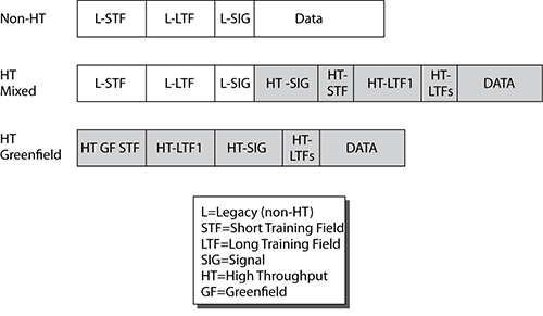
The non-HT PPDU is often also referred to as a legacy format because it was originally defined by clause 17 of the 802.11-2007 standard for OFDM transmissions. The packets are structured according to the clause 17 (OFDM) or clause 19 (ERP) specification. As pictured in Figure 2-5, the non-HT PPDU consists of a preamble that uses short and long training symbols, which are used for synchronization. The preamble consists of 10 short symbols and 2 long symbols.
Figure 2-5: 802.11n PPDU formats
Support for the non-HT legacy format is mandatory for 802.11n radios, and transmissions can occur in only 20 MHz channels. The non-HT format effectively is the same format used by legacy 802.11a and 802.11g radios.
HT-Mixed PPDU
The first of the two new PPDU formats defined in the 802.11n amendment is the HT-mixed format. As shown in Figure 2-4, the beginning of the preamble contains the non-HT short and long training symbols that can be decoded by legacy 802.11a (clause 17 OFDM) or 802.11g (clause 19 ERP) radios, enabling them to detect the PPDU and acquire the carrier frequency and timing.
The rest of the HT-mixed preamble and header cannot be decoded by legacy 802.11 devices but can be decoded by HT devices, allowing them to also detect the PPDU and acquire the carrier frequency and timing. The HT portion of the preamble also enables estimation of the MIMO channel, providing HT STAs with the necessary information to demodulate the HT data.
The HT-mixed format will likely be the most commonly used format because it supports both HT and legacy 802.11a/g OFDM radios. Support of the HT-mixed format is also considered mandatory, and transmissions can occur in both 20 MHz and 40 MHz channels. When a 40 MHz channel is used, all broadcast traffic must be sent on a legacy 20 MHz channel so as to maintain interoperability with the 802.11a/g non-HT clients. Also, any transmissions to and from the non-HT clients will have to use a legacy 20 MHz channel.
HT-greenfield PPDU
The second of the two new PPDU formats defined by the 802.11n amendment is the HT-greenfield format. As pictured in Figure 2-4, the preamble is not compatible with legacy 802.11 radios, and only HT radios can communicate when using the HT-greenfield format. Support for the HT-greenfield format is optional, and the HT radios can transmit by using both 20 MHz and 40 MHz channels.
Data Field
The data field portion of the PPDU is the PSDU. In the Long and Short PPDUs, the data field is simply the MPDU passed down from the Data-Link layer. In layperson terms, the data field is the 802.11 MAC frame. The data field of the non-HT legacy, HT-mixed, and HT-greenfield PPDUs is displayed in Figure 2-6, and is the same as the data fields from clause 17 (OFDM) and 19 (ERP-OFDM). In these PPDUs, the Service field is prepended to the scrambled PSDU. Scrambling is used to randomize the PSDU, which could have long strings of 0s or 1s.
Figure 2-6: 802.11n-defined PPDU Data field

The 2.4 GHz ISM band is the most common band used for wireless networking communications. The 2.4 GHz ISM band is 83.5 MHz wide and spans from 2.4000 GHz to 2.4835 GHz. Use of the 2.4 GHz ISM band for wireless LANs is defined by the IEEE in the 802.11-2007 standard. The bulk of Wi-Fi radios currently transmit in the 2.4 GHz ISM band, including radios that use the following technologies:
- 802.11 (FHSS clause 14 radios or DSSS clause 15 radios)
- 802.11b (HR-DSSS clause 18 radios)
- 802.11g (ERP clause 19 radios)
- 802.11n (HT clause 20 radios)
In addition to being used by wireless networking equipment, the 2.4 GHz ISM band is also used by microwave ovens, cordless home telephones, baby monitors, wireless video cameras, and many other devices. The 2.4 GHz ISM band is heavily used, and one of the big disadvantages of using 802.11b/g radios is the potential for interference.
Please keep in mind that not every country’s RF regulatory body will allow for transmissions across the entire 2.4 to 2.4835 GHz ISM band. The IEEE 802.11-2007 standard allows for WLAN transmissions in this band across 14 channels. However, each country can determine which channels can be used.
2.4 GHz Channels
To better understand how legacy 802.11 (DSSS), 802.11b (HR-DSSS), and 802.11g (ERP) radios are used, it is important to understand how the IEEE 802.11-2007 standard divides the 2.4 GHz ISM band into 14 separate channels, as listed in Table 2-1. Although the 2.4 GHz ISM band is divided into 14 channels, the FCC or other local regulatory body designates which channels are allowed to be used. Table 2-1 also shows what channels are supported in a sample of a few countries. As you can see, the regulations can vary greatly between countries.
Table 2-1: 2.4 GHz frequency channel plan
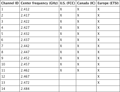
X = supported channel
Channels are designated by their center frequency. Each channel is 22 MHz wide and is often referenced by the center frequency ±11 MHz. For example, channel 1 is 2.412 GHz ±11 MHz, which means that channel 1 spans from 2.401 GHz to 2.423 GHz. It should also be noted that within the 2.4 GHz ISM band, the distance between channel center frequencies is only 5 MHz, with the exception of channel 14. Because each channel is 22 MHz wide and because the separation between center frequencies of each channel is only 5 MHz, the channels will have overlapping frequency space.
Figure 2-7 shows an overlay of all the channels and how they overlap. Channels 1, 6, and 11 have been highlighted because, as you can see, they are separated from each other by enough frequencies that they do not overlap. For two channels to not overlap, they must be separated by at least five channels or 25 MHz. Channels, such as 2 and 9, do not overlap, but by selecting 2 and 9, there is no additional legal channel that can be chosen that does not overlap either 2 or 9. In the United States and Canada, the only three simultaneously nonoverlapping channels are 1, 6, and 11. In regions where channels 1 through 13 are allowed to be used, there are different combinations of three nonoverlapping channels, although channels 1, 6, and 11 are usually chosen.
Figure 2-7: 2.4 GHz channel overlay diagram

The IEEE 802.11-2007 definitions of nonoverlapping channels in the 2.4 GHz ISM band can be somewhat confusing if not properly explained. Legacy 802.11 (DSSS), 802.11b (HR-DSSS), and 802.11g (ERP) channels all use the same numbering schemes and have the same center frequencies. However, the individual channels’ frequency space may overlap. Figure 2-8 shows channels 1, 6, and 11 with 25 MHz of spacing between the center frequencies. These are the most commonly used nonoverlapping channels in North America and most of the world for 802.11b/g networks.
Figure 2-8: HR-DSSS center frequencies
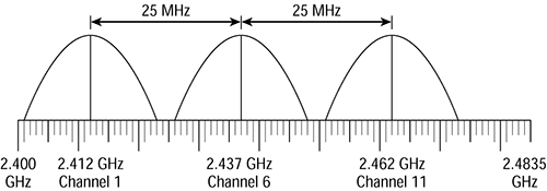
What exactly classifies DSSS or HR-DSSS channels as nonoverlapping? According to the original 802.11 standard, legacy DSSS channels had to have at least 30 MHz of spacing between the center frequencies to be considered nonoverlapping. In a deployment of legacy DSSS equipment using a channel pattern of 1, 6, and 11, the channels were considered overlapping because the center frequencies were only 25 MHz apart. Although DSSS channels 1, 6, and 11 were defined as overlapping, these were still the only three channels used in channel reuse patterns when legacy networks were deployed. This really is of little significance anymore because most 2.4 GHz deployments now use 802.11b/g/n technology.
HR-DSSS was introduced under the 802.11b amendment, which states that channels need a minimum of 25 MHz of separation between the center frequencies to be considered nonoverlapping. Therefore, when 802.11b was introduced, channels 1, 6, and 11 were considered nonoverlapping.
The 802.11g amendment, which allows for backward compatibility with 802.11b HR-DSSS, also requires 25 MHz of separation between the center frequencies to be considered nonoverlapping. Under the 802.11g amendment, channels 1, 6, and 11 are also considered nonoverlapping for both ERP-DSSS/CCK and ERP-OFDM.
Although it is very common to represent the RF signal of a particular channel with an arch-type line, this is not a true representation of the signal. To explain it simply, in addition to the main carrier frequency, or main frequency, sideband carrier frequencies are also generated, as shown in Figure 2-9. The IEEE defines a transmit spectrum mask for DSSS and HR-DSSS transmissions specifying that the first sideband frequency (–11 MHz to –22 MHz from the center frequency, and +11 MHz to +22 MHz from the center frequency) must be at least 30 dB less than the main frequency. The mask also specifies that any additional sideband carrier frequencies (–22 MHz from the center frequency and beyond, and +22 MHz from the center frequency and beyond) must be at least 50 dB less than the main frequency.
Figure 2-9: IEEE 802.11b transmit spectrum mask
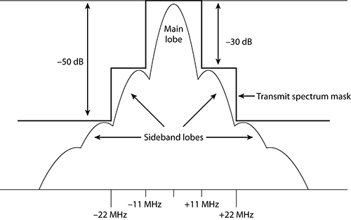
Figure 2-9 illustrates the transmit spectrum mask of an HR-DSSS channel at 2.4 GHz. The transmit spectrum mask is defined to minimize interference between devices on different frequencies. Even though the sideband carrier frequencies are mere whispers of signals compared to the main carrier frequency, even a whisper is noticeable when the person whispering is close to you. This is true for RF devices too.
Figure 2-10 represents RF signals on channels 1, 6, and 11. A signal-level line indicates an arbitrary level of reception by the access point on channel 6. At level 1, meaning the AP on channel 6 receives only the signals above the level 1 line, the signals from channel 1 and channel 11 do not intersect (interfere) with the signals on channel 6. However, at the level 2 line, the signals from channel 1 and channel 11 do intersect (interfere) slightly with the signals on channel 6. At the level 3 line, there is significant interference from the signals from channel 1 and channel 11. Because of the potential for this situation, it is important to separate access points (usually 5 to 10 feet is sufficient) so that interference from sideband frequencies does not occur. This is important both horizontally and vertically.
Figure 2-10: Sideband carrier frequency interference

The IEEE 802.11a amendment designated WLAN transmissions within the frequency space of the three 5 GHz bands, each with four channels. These frequency ranges are known as the Unlicensed National Information Infrastructure (UNII) bands. The 802.11a amendment defined three groupings, or bands, of UNII frequencies, often known as the lower, middle, and upper UNII bands. These three bands are typically designated as UNII-1 (lower), UNII-2 (middle), and UNII-3 (upper). All three of these bands are 100 MHz wide, which is a useful fact when trying to remember their frequency ranges.
When the 802.11h amendment was ratified, the IEEE had recently designated more frequency space for WLAN transmissions. This frequency space, which consists of 11 additional channels, is often referred to as UNII-2 Extended. Unlike the other three UNII bands that are 100 MHz wide, this new band is 255 MHz wide.
Although we use UNII as the abbreviation, many documents will show U-NII as the abbreviation. Both abbreviations are common and acceptable.
Wi-Fi radios that currently transmit in the 5 GHz UNII bands include radios that use the following protocols:
- 802.11a (OFDM clause 17 radios)
- 802.11h (TPC and DFS)
- 802.11n (HT clause 20 radios)
Please keep in mind that not every country’s RF regulatory body will allow for transmissions in all these bands. The IEEE 802.11-2007 standard allows for WLAN transmissions in all four of the bands across 23 channels. However, each country may be different. A more detailed discussion of all the 5 GHz channels occurs later in this chapter.
UNII-1 (Lower Band)
UNII-1, the lower UNII band, is 100 MHz wide and spans from 5.150 GHz to 5.250 GHz. This band is typically used indoors with a maximum allowed output power of 50 mW at the intentional radiator (IR) as defined by the FCC. The IEEE has implemented a transmit power cap of 40 mW, which complies with the FCC maximum. Prior to 2004, the FCC required that all UNII-1–capable devices have permanently attached antennas. This meant that any 802.11a device that supported UNII-1 could not have a detachable antenna, even if the device supported other frequencies or standards.
In 2004, the FCC changed the regulations to allow detachable antennas, providing that the antenna connector is unique. This requirement is similar to the antenna requirements for the other UNII bands and the 2.4 GHz ISM band. Some access point manufacturers allow the ability to configure the device as a bridge and to work in the lower UNII band. Care must be taken to make sure you do not exceed the limitations of your local regulatory body.
UNII-2 (Middle Band)
UNII-2, the middle UNII band, is 100 MHz wide and spans from 5.250 GHz to 5.350 GHz. The FCC allows this band to be used for indoor or outdoor communications, with a maximum allowed output power of 250 mW. The IEEE has implemented a restriction on 802.11 devices of only 200 mW at the intentional radiator, which complies with the FCC maximum. Local regulatory agencies may impose other restrictions that you will need to comply with.
UNII-2 Extended
The UNII-2 Extended band is 255 MHz wide and spans from 5.470 GHz to 5.725 GHz. This band can be used for indoor or outdoor communications, with a maximum allowed output power of 250 mW as defined by the FCC. The IEEE has restricted that to 200 mW at the intentional radiator, which complies with the FCC maximum. Local regulatory agencies may impose other restrictions that you will need to comply with. Operations for WLAN communications were first allowed in this band with the ratification of the 802.11h amendment. Prior to the ratification of this amendment, 5 GHz WLAN communications were allowed in only UNII-1, UNII-2, and UNII-3.
The 802.11h amendment defined the use of transmit power control (TPC) and dynamic frequency selection (DFS) to avoid interference with other devices that use these bands, such as radar transmissions. Any 5 GHz WLAN products that ship in the United States or Canada on or after July 20, 2007, are required to support dynamic frequency selection. 802.11h was actually first implemented in Europe in 2005 and was driven by ETSI. FCC Rule # 15.407(h)(2) requires that WLAN products operating in the UNII-2 and UNII-2 Extended bands must support DFS, to protect WLAN communications from interfering with the other devices that use these bands, such as military or weather radar systems. As mentioned earlier, Europe also requires DFS safeguards. Once again, the local regulatory agencies determine how TPC and DFS restrictions are imposed in any of the UNII bands.
UNII-3 (Upper Band)
UNII-3, the upper UNII band, is 100 MHz wide and spans from 5.725 GHz to 5.825 GHz. This band is typically used for outdoor point-to-point communications but can also be used indoors in some countries, including the United States. Europe does not use the UNII-3 band for WLAN communications. The maximum allowed output power by the FCC is 1000 mW. The IEEE has implemented a power restriction of 800 mW at the intentional radiator, which complies with the FCC maximum. Table 2-2 shows a comparison between the four bands.
Table 2-2: The 5 GHz UNII bands


The CWAP exam will not test you on any power regulations because they vary from country to country. It is advisable to educate yourself about the maximum transmit power regulations of the country where you plan on deploying a WLAN so that no violations occur. The CWAP exam may test you on your knowledge of the frequency ranges of all the ISM and UNII bands or the power restrictions implemented by the IEEE.
5 GHz Channels
The 802.11-2007 standard specifies the channels defined in the 5 GHz UNII bands: UNII-1, UNII-2, UNII-2 Extended, and UNII-3. The centers of the outermost channels must be 30 MHz from the band’s edge in the UNII-1 and UNII-2 bands and must be 20 MHz in the UNII-3 band. The original three UNII bands each have four nonoverlapping channels with 20 MHz separation between the center frequencies. The UNII-2 Extended band has 11 nonoverlapping channels with 20 MHz of separation between the center frequencies. The United States also allows for OFDM transmissions on ISM channel 165, whose center frequency is 5.825 GHz, which is at the upper edge of the UNII-3 band. Channel 165 resides squarely within the FCC’s 5.725–5.875 GHz ISM band. With the addition of channel 165, there are potentially up to 24 usable 5 GHz channels.
Figure 2-11 shows the 8 UNII-1 and UNII-2 channels in the top graphic, the 11 UNII-2 Extended channels in the center graphic, and the 4 UNII-3 channels, along with ISM channel 165 in the bottom graphic. Channel 36 is highlighted so that it is easier to distinguish a single carrier and its sideband frequencies. The IEEE defines the center frequency of each channel as follows, where nch is all values from 0 through 200:
5,000 + 5 × nch (MHz)
Figure 2-11: UNII channel overview
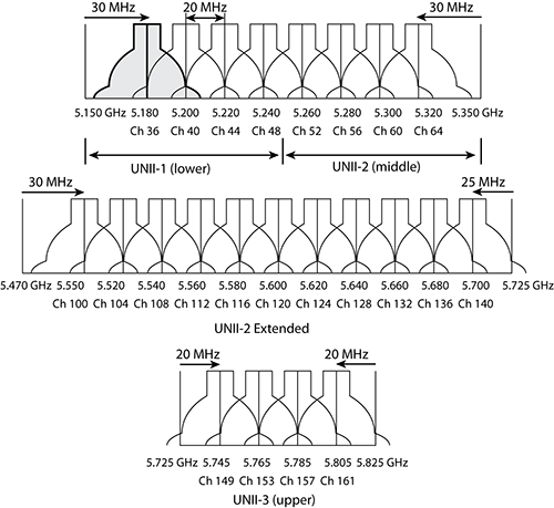
The IEEE does not specifically define a channel width; however, the spectral mask of an OFDM channel is approximately 20 MHz.
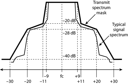
As shown in Figure 2-12 of the OFDM spectrum mask, the sideband carrier frequencies do not drop off very quickly, and therefore the sideband frequencies of two adjacent valid channels overlap and are more likely to cause interference. The 802.11a amendment, which originally defined the use of OFDM (clause 17), required only 20 MHz of separation between the center frequencies for channels to be considered nonoverlapping. All 23 channels in the 5 GHz UNII bands use OFDM and have 20 MHz of separation between the center frequencies. Therefore, all 5 GHz OFDM channels are considered nonoverlapping by the IEEE. In reality, there is some sideband carrier frequency overlap between any two adjacent 5 GHz channels. Luckily, because of the number of channels and the channel spacing of 802.11a, it is easier to separate adjacent channels and prevent interference.
Figure 2-12: OFDM spectrum mask
Adjacent, Nonadjacent, and Overlapping Channels
In the preceding paragraphs, you learned how the IEEE 802.11-2007 standard defines nonoverlapping channels. DSSS (legacy) channels require 30 MHz of separation between the center frequencies to be considered nonoverlapping. HR-DSSS (802.11b) and ERP (802.11g) channels require 25 MHz of separation between the center frequencies to be considered nonoverlapping. And finally, 5 GHz OFDM channels require 20 MHz of separation between the center frequencies to be considered nonoverlapping.
An often debated topic is what defines an adjacent channel and nonadjacent channel. The 802.11-2007 standard loosely defines an adjacent channel as any channel with nonoverlapping frequencies for the DSSS and HR-DSSS PHYs. With ERP and OFDM implementations, the standard loosely defines an adjacent channel as the first channel with a nonoverlapping frequency space. In other words, the IEEE’s definition of adjacent channels is almost exactly the same as the definition of nonoverlapping channels that has been discussed earlier. Confused? Table 2-3 illustrates the CWNP program’s interpretation of these concepts.
Table 2-3: Adjacent vs. nonadjacent

Frequency hopping spread spectrum (FHSS) was used in the original 802.11 standard and provided 1 and 2 Mbps RF communications using the 2.4 GHz ISM band for legacy clause 14 radios. The majority of 802.11-compliant legacy FHSS radios were manufactured between 1997 and 1999. The IEEE specified that in North America, 802.11 FHSS would use 79 MHz of frequencies, from 2.402 GHz to 2.480 GHz.
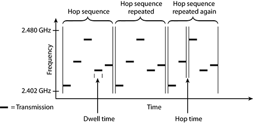
Generally, the way FHSS works is that it transmits data by using a small frequency carrier space and then hops to another small frequency carrier space and transmits data, then to another frequency, and so on, as illustrated in Figure 2-13. More specifically, frequency hopping spread spectrum transmits data by using a specific frequency for a set period of time, known as the dwell time. When the dwell time expires, the system changes to another frequency and begins to transmit on that frequency for the duration of the dwell time. Each time the dwell time is reached, the system changes to another frequency and continues to transmit.
Figure 2-13: FHSS components
Hopping Sequence
FHSS radios use a predefined hopping sequence (also called a hopping pattern or hopping set) comprising a series of small carrier frequencies, or hops. Instead of transmitting on one set channel or finite frequency space, an FHSS radio card transmits on a sequence of subchannels called hops. Each time the hop sequence is completed, it is repeated. Figure 2-13 shows a make-believe hopping sequence that consists of five hops.
The original IEEE 802.11 standard mandates that each hop is 1 MHz in size. These individual hops are then arranged in predefined sequences. In North America and most of Europe, the hopping sequences contain at least 75 hops, but no greater than 79 hops. Other countries have different requirements; for example, France uses 35 hops, while Spain and Japan use 23 hops in a sequence. For successful transmissions to occur, all FHSS transmitters and receivers must be synchronized on the same carrier hop at the same time. The 802.11 standard defines hopping sequences that can be configured on an FHSS access point, and the hopping sequence information is delivered to client stations via the beacon management frame.
Dwell Time
Dwell time is a defined amount of time that the FHSS system transmits on a specific frequency before it switches to the next frequency in the hop set. The local regulatory body typically limits the amount of dwell time. For example, the FCC specifies a maximum dwell time of 400 milliseconds (ms) per carrier frequency during any 30-second period of time. Typical dwell times are around 100ms to 200ms. The IEEE 802.11 standard specifies that a hopping sequence must consist of at least 75 frequencies, 1 MHz wide. Because the standard specifies a maximum bandwidth of 79 MHz, the maximum number of hops possible for a hop set would be 79. With an FHSS hop sequence consisting of 75 hops and a dwell time of 400ms, it would take about 30 seconds to complete the hop sequence. After the hop sequence is complete, it is repeated.
Hop Time
Hop time is not a specified period of time but rather a measurement of the amount of time it takes for the transmitter to change from one frequency to another. Hop time is typically a fairly small number, often about 200 to 300 microseconds (µs). With typical dwell times of 100 ms to 200 ms, hop times of 200 µs to 300 µs are insignificant. Insignificant or not, the hop time is essentially wasted time, or overhead, and takes up the same amount of time regardless of the dwell time. The longer the dwell time, the less often the transmitter has to waste time hopping to another frequency, thus greater throughput. If the dwell time is shorter, the transmitter has to hop more frequently, thus decreasing throughput.
Modulation
FHSS uses Gaussian Frequency Shift Keying (GFSK) to encode the data. Two-level GFSK (2GFSK) uses two frequencies to represent a 0 bit or a 1 bit. Four-level GFSK (4GFSK) uses four frequencies, with each frequency representing 2 bits (00, 01, 10, or 11). Because it takes cycles before the frequency can be determined, the symbol rate (rate that the data is sent) is only about 1 or 2 million symbols per second, a fraction of the 2.4 GHz carrier frequency.
What Is the Significance of the Dwell Time?
Because FHSS transmissions jump inside a frequency range of 79 MHz, a narrowband signal or noise would disrupt only a small range of frequencies and would produce only a minimal amount of throughput loss. Decreasing the dwell time can further reduce the effect of interference. Conversely, because the radio card is transmitting data during the dwell time, the longer the dwell time and the greater the throughput.
Direct sequence spread spectrum (DSSS) was originally specified in the primary, or root, 802.11 standard and provides 1 Mbps and 2 Mbps RF communications using the 2.4 GHz ISM band. HR/DSSS was also specified in the 802.11b addendum and provides 5.5 Mbps and 11 Mbps RF communications using the same 2.4 GHz ISM band.
DSSS 1 and 2 Mbps are specified in clause 15 of the 802.11-2007 standard. HR-DSSS 5.5 and 11 Mbps are specified in clause 18 of the 802.11-2007 standard.
Unlike FHSS, where the transmitter jumped between frequencies, DSSS is set to one channel. The data that is being transmitted is spread across the range of frequencies that make up the channel. The process of spreading the data across the channel is known as data encoding.
DSSS Data Encoding
RF signals can get altered or corrupted in many ways. Because 802.11 is an unbounded medium with a huge potential for RF interference, it had to be designed to be resilient enough that data corruption could be minimized. To achieve this, each bit of data is encoded and transmitted as multiple bits of data.
The task of adding additional, redundant information to the data is known as processing gain. In this day and age of data compression, it seems strange that we would use a technology that adds data to our transmission, but by doing so, the communication is more resistant to data corruption. The system converts the 1 bit of data into a series of bits that are referred to as chips. To create the chips, a Boolean XOR is performed on the data bit and a fixed-length bit sequence pseudo-random number (PN) code. Using a PN code known as the Barker code, the binary data 1 and 0 are represented by the following chip sequences:
Binary data 1 = 1 0 1 1 0 1 1 1 0 0 0
Binary data 0 = 0 1 0 0 1 0 0 0 1 1 1
This sequence of chips is then spread across a wider frequency space. Although 1 bit of data might need only 2 MHz of frequency space, the 11 chips will require 22 MHz of frequency carrier. This process of converting a single data bit into a sequence is often called spreading or chipping. The receiving radio card converts, or de-spreads, the chip sequence back into a single data bit. When the data is converted to multiple chips and some of the chips are not received properly, the radio will still be able to interpret the data by looking at the chips that were received properly. When the Barker code is used, as many as 9 of the 11 chips can be corrupted, yet the receiving radio card will still be able to interpret the sequence and convert them back into a single data bit. This chipping process also makes the communication less likely to be affected by intersymbol interference because it uses more bandwidth.
After the Barker code is applied to data, a series of 11 bits, referred to as chips, represent the original single bit of data. This series of encoded bits makes up 1 bit of data. To help prevent confusion, it is best to think of and refer to the encoded bits as chips.
Modulation
After the data has been encoded using a chipping method, the transmitter needs to modulate the signal to create a carrier signal containing the chips. Differential Binary Phase Shift Keying (DBPSK) utilizes two phase shifts, one that represents a 0 chip and another that represents a 1 chip. Differential Quadrature Phase Shift Keying (DQPSK) is an enhancement to DBPSK, utilizing four phase shifts, representing, allowing each phase shift to represent two chips; 00, 01, 10, or 11. Table 2-4 summarizes the data encoding and modulation techniques used by 802.11.
Table 2-4: DSSS encoding and modulation overview

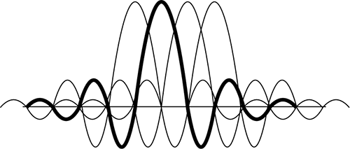
Orthogonal Frequency Division Multiplexing (OFDM) is one of the most popular communications technologies, used in both wired and wireless communications. The 802.11-2007 standard specifies the use of OFDM at 5 GHz and also specifies the use of ERP-OFDM at 2.4 GHZ. OFDM and ERP-OFDM are the same technology. OFDM is not a spread spectrum technology, even though it has similar properties to spread spectrum, such as low transmit power and using more bandwidth than is required to transmit data. Because of these similarities, OFDM is often referred to as a spread spectrum technology even though technically that reference is incorrect. OFDM actually transmits across 52 separate, closely and precisely spaced frequencies, often referred to as subcarriers, as illustrated in Figure 2-14.
The frequency width of each subcarrier is 312.5 KHz. The subcarriers are also transmitted at lower data rates, but because there are so many subcarriers, overall data rates are higher. Also, because of the lower subcarrier data rates, delay spread is a smaller percentage of the symbol period, which means that intersymbol interference (ISI) is less likely to occur. In other words, OFDM technology is more resistant to the negative effects of multipath than DSSS and FHSS spread spectrum technologies. Figure 2-15 represents four of the 52 subcarriers. One of the subcarriers is highlighted so that you can more easily understand the drawing. Notice that the frequency spacing of the subcarriers has been chosen so that the harmonics overlap and provide cancellation of most of the unwanted signals.
The 52 subcarriers are numbered from –26 to +26. Forty-eight of the subcarriers are used to transmit data. The other four, numbers –21, –7, +7, and +21, are known as pilot carriers. These four are used as references for phase and amplitude by the demodulator, allowing the receiver to compensate for distortion of the OFDM signal.
Figure 2-14: 802.11 channels and OFDM subcarriers

Figure 2-15: Subcarrier signal overlay
Convolutional Coding
To make OFDM more resistant to narrowband interference, a form of error correction known as convolutional coding is performed. The 802.11-2007 standard defines the use of convolutional coding as the error-correction method to be used with OFDM technology. It is a forward error correction (FEC) that allows the receiving system to detect and repair corrupted bits.
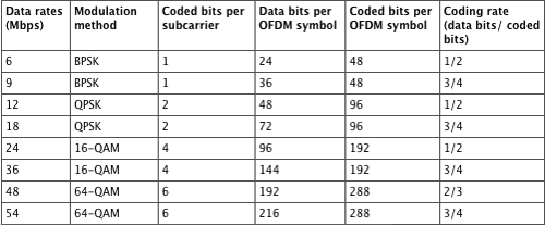
There are many levels of convolutional coding. Convolutional coding uses a ratio between the bits transmitted vs. the bits encoded to provide these different levels. The lower the ratio, the less resistant the signal is to interference and the greater the data rate will be. Table 2-5 displays a comparison between the technologies used to create the different data rates of both 802.11a and 802.11g. Notice that the data rates are grouped by pairs based on modulation technique and that the difference between the two speeds is caused by the different levels of convolutional coding. A detailed explanation of convolutional coding is extremely complex and even beyond the knowledge needed for the CWAP exam.
Table 2-5: 802.11a and 802.11g data rate and modulation comparison chart
Modulation
OFDM uses Binary Phase Shift Keying (BPSK) and Quadrature Phase Shift Keying (QPSK) phase modulation for the lower ODFM data rates. The higher OFDM data rates use 16-QAM and 64-QAM modulation. Quadrature amplitude modulation (QAM) is a hybrid of phase and amplitude modulation.
Clause 18 devices were originally defined in the 802.11b amendment. The 802.11b 5.5 and 11 Mbps speeds are known as High-Rate DSSS (HR-DSSS). 802.11b clause 18 devices are backward compatible with the legacy 802.11 DSSS clause 15 devices. This means that an 802.11b device can transmit using DSSS at 1 Mbps and 2 Mbps and using HR-DSSS at 5.5 Mbps and 11 Mbps. However, 802.11b devices are not capable of transmitting using FHSS; therefore, they are not backward compatible with 802.11 FHSS clause 14 devices.
To help provide the faster speeds of HR-DSSS, a more complex code, Complementary Code Keying (CCK), is utilized instead of the Barker code that is used with DSSS transmissions. CCK uses an eight-chip pseudorandom number (PN), along with using different PNs for different bit sequences. CCK can encode 4 bits of data with 8 chips (5.5 Mbps) and can encode 8 bits of data with 8 chips (11 Mbps).
Modulation
As mentioned earlier in this chapter, after the data has been encoded using a chipping method, the transmitter needs to modulate the signal to create a carrier signal containing the chips. DSSS uses DBPSK and DQPSK to modulate the data at 1 Mbps and 2 Mbps. To provide the faster throughput for HR-DSSS, Complimentary Code Keying (CCK) is used to encode and modulate the data.
Table 2-6 summarizes the data encoding and modulation techniques used by 802.11b.
Table 2-6: HR-DSSS encoding and modulation overview

Another amendment that generated a lot of excitement in the Wi-Fi marketplace was published as IEEE Std. 802.11g-2003. The IEEE defines 802.11g cards as clause 19 devices, which transmit in the 2.4 GHz to 2.4835 GHz ISM frequency band. Clause 19 defines a technology called Extended Rate Physical (ERP). All aspects of the 802.11g ratified amendment can now be found in clause 19 of the 802.11-2007 standard.
The main goal of the Task Group g (TGg) was to enhance the 802.11b Physical layer to achieve greater bandwidth yet remain compatible with the 802.11 MAC. Two mandatory and two optional ERP physical layers (PHYs) were defined by the 802.11g amendment.
The mandatory PHYs are ERP-OFDM and ERP-DSSS/CCK. To achieve the higher data rates, a PHY technology called Extended Rate Physical OFDM (ERP-OFDM) is mandated. Data rates of 6, 9, 12, 18, 24, 36, 48, and 54 Mbps are possible using this technology, although the IEEE requires only the data rates of 6, 12, and 24 Mbps. To maintain backward compatibility with 802.11 (DSSS only) and 802.11b networks, a PHY technology called Extended Rate Physical DSSS (ERP-DSSS/CCK) is used with support for the data rates of 1, 2, 5.5, and 11 Mbps.
What Is the Difference Between ERP-DSSS/CCK, DSSS, and HR-DSSS?
From a technical viewpoint, there is no difference between ERP-DSSS/CCK and DSSS and HR-DSSS. A key point of the 802.11g amendment was to maintain backward compatibility with older 802.11 (DSSS only) and 802.11b radios while at the same time achieving higher data rates. 802.11g devices (clause 19 radios) use ERP-OFDM for the higher data rates. ERP-DSSS/CCK is effectively the same technology as the DSSS that is used by legacy 802.11 devices (clause 15 radios) and HR-DSSS that is used by 802.11b devices (clause 18 radios). Mandated support for ERP-DSSS/CCK allows for backward compatibility with older 802.11 (DSSS only) and 802.11b radios.
The 802.11g ratified amendment also defined two optional PHYs called ERP-PBCC and DSSS-OFDM. These optional technologies are rarely used by WLAN vendors.
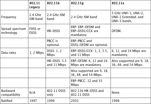
As you have learned, the 802.11g amendment requires support for both ERP-DSSS/CCK and ERP-OFDM. The good news is that an 802.11g AP can communicate with 802.11g client stations as well as 802.11 (DSSS only) or 802.11b stations. The ratification of the 802.11g amendment triggered monumental sales of Wi-Fi gear in both the small office/home office (SOHO) and enterprise markets because of both the higher data rates and the backward compatibility with older equipment. As mentioned earlier in this chapter, different spread spectrum technologies cannot communicate with each other, yet the 802.11g amendment mandates support for both ERP-DSSS/CCK and ERP-OFDM. ERP-OFDM and ERP-DSSS/CCK technologies can coexist, yet they cannot speak to each other. Therefore, the 802.11g amendment calls for a protection mechanism that allows the two technologies to coexist. The goal of the protection mechanism is to prevent older 802.11b HR-DSSS or 802.11 DSSS radio cards from transmitting at the same time as 802.11g (ERP) radio cards. Table 2-7 shows a brief overview and comparison of 802.11, 802.11b, 802.11g, and 802.11a.
What Is the Difference Between OFDM and ERP-OFDM?
From an 802.11 technical viewpoint, there is no difference between OFDM and ERP-OFDM. The only difference is the transmit frequency. OFDM refers to 802.11a devices (clause 17 radios) that transmit in the 5 GHz UNII-1, UNII-2, UNII-2E, and UNII-3 frequency bands. ERP-OFDM refers to 802.11g devices (clause 19 radios) that transmit in the 2.4 GHz ISM frequency band. The technology is explained further in Chapter 6.
Table 2-7: 802.11 amendment comparison
The 802.11a amendment defined the use of clause 17 radios using Orthogonal Frequency Division Multiplexing (OFDM) technology in the 5 GHz UNII bands. 802.11g defined the use of clause 19 radios using ERP-OFDM, which is effectively the same technology except that transmissions occur in the 2.4 GHz ISM band. The 802.11n amendment also defines the use of OFDM channels. However, key differences exist for HT clause 20 radios. The changes and additions introduced by the 802.11n amendment are so significant and important that there is an entire chapter designated to 802.11n. Chapter 10, “802.11n—HT Analysis,” discusses in-depth analysis of 802.11n, along with a complete overview of its Physical layer implementation and components.
In this chapter, you looked at the Physical layer and the components that are used in taking the data from the Data-Link Layer and transmitting it into the air. You also looked at the 2.4 GHz and 5 GHz bands that are used by 802.11, along with the channel and power specifications defined by the IEEE. Each of the Physical layer standards were also reviewed, with exception of 802.11n defined in clause 20, which is reviewed later in a different chapter in this book.
Explain the differences between a PPDU, PSDU, MPDU, and MSDU. Understand at which layer of the OSI model each data unit operates and what comprises each data unit. Although this chapter focuses on the Physical layer, it is important to understand the relationship between all four of the data units.
Know the different Physical layer implementations. Know the differences and similarities of the Physical layer implementations. Understand how they interact with the upper layers and how they work to provide wireless communications.
Differentiate between adjacent, nonadjacent, and overlapping channels. It is important to understand how channels relate to other channels and how they can interfere with each other.
adjacent channel
carrier frequency
chipping
chips
Complementary Code Keying (CCK)
convolutional coding
data encoding
de-spreads
Differential Binary Phase Shift Keying (DBPSK)
Differential Binary Phase Shift Keying (DBPSK)
Differential Quadrature Phase Shift Keying (DQPSK)
Direct sequence spread spectrum (DSSS)
DSSS-OFDM
dwell time
ERP-PBCC
Extended Rate Physical (ERP)
Extended Rate Physical DSSS (ERP-DSSS/CCK)
Extended Rate Physical OFDM (ERP-OFDM)
forward error correction (FEC)
Frequency hopping spread spectrum (FHSS)
High-Rate DSSS (HR-DSSS)
Hop time
hopping sequence
hops
HT-greenfield
HT-mixed
Long PPDU
MAC Protocol Data Unit (MPDU)
nonadjacent channel
non-HT PPDU
nonoverlapping channels
Orthogonal Frequency Division Multiplexing (OFDM)
Physical layer
Physical Layer Convergence Procedure (PLCP) sublayer
Physical Medium Dependent (PMD) sublayer
pilot carriers
PLCP Header
PLCP Preamble
PLCP Protocol Data Unit (PPDU)
PLCP Service Data Unit (PSDU)
processing gain
protection mechanism
Quadrature amplitude modulation (QAM)
Short PPDU
Signal field
spreading
Start of Frame Delimiter (SFD)
subcarriers
Sync field
transmit spectrum mask
Unlicensed National Information Infrastructure (UNII) bands
1. The 802.11-2007 standard requires how much separation between center frequencies for HR-DSSS (clause 18) channels to be considered nonoverlapping?
A. 22 MHz
B. 25 MHz
C. 30 MHz
D. 35 MHz
E. 40 MHz
2. The upper portion of the Physical layer is known as the , and the lower portion is known as the .
A. PPDU
B. PMD
C. PSDU
D. PLCP
E. MSDU
3. What three parts make up the PPDU? (Choose all that apply.)
A. PMD
B. PLCP Preamble
C. PLCP Header
D. PSP
E. PLCP Service Data Unit (PSDU)
4. The Long PPDU includes a -bit PLCP Preamble, which consists of a -bit Sync field.
A. 144, 128
B. 72, 56
C. 256, 212
D. 144, 72
E. 128, 72
5. Both the Long and Short Preambles are transmitted using which modulation technique?
A. DBPSK
B. DQPSK
C. 2GFSK
D. 4GFSK
E. 16-QAM
6. Which of the following fields are contained in the Long and Short PLCP Headers? (Choose all that apply.)
A. Service
B. Length
C. Signal
D. Preamble
E. CRC
7. Which PPDUs were defined by the 802.11n amendment? (Choose all that apply.)
A. Non-HT legacy PPDU
B. HT PPDU
C. HT-mixed PPDU
D. Combined HT Legacy PPDU
E. HT-greenfield PPDU
8. Which of the following define radios that can transmit in the 2.4 GHz ISM band? (Choose all that apply.)
A. Clause 14
B. Clause 15
C. Clause 18
D. Clause 19
E. Clause 20
9. Clause 17 defines communications using which of the following modulation methods? (Choose all that apply.)
A. DBPSK
B. BPSK
C. QPSK
D. 16-QAM
E. 64-QAM
10. According to the IEEE, clause 17 and clause 19 require which of the following data rates? (Choose all that apply.)
A. 6
B. 9
C. 12
D. 18
E. 24
F. 54
11. In descending order (moving from the Application layer toward the Physical), list the 4 sublayers that make up the Data-Link and Physical layers.
A. LLC, MAC, PSDU, PLCP
B. MAC, LLC, PSDU, PLCP
C. PMD, PLCP, MAC, LLC
D. LLC, MAC, PLCP, PMD
E. MAC, LLC, PLCP, PMD
12. When a Long PLCP Header is used, what speeds can be used for transmitting the PSDU? (Choose all that apply.)
A. 1 Mbps
B. 2 Mbps
C. 5.5 Mbps
D. 11 Mbps
E. 54 mbps
13. According to the 802.11n amendment, which of the following PPDU formats is optional?
A. Long PPDU
B. Short PPDU
C. Non-HT legacy PPDU
D. HT-mixed PPDU
E. HT-greenfield PPDU
14. How wide are the UNII-1, UNII-2, and UNII-3 bands?
A. 20 MHz
B. 22 MHz
C. 11 MHz
D. 100 MHz
E. It varies depending upon the specific band.
15. What are the boundaries of the UNII-2 Extended bands?
A. 5.470 GHz to 5.725 GHz
B. 5.5 GHz to 5.75 GHz
C. 2.4 GHz to 2.4835 GHz
D. 902 MHz to 928 MHz
16. What is the frequency width of each clause 17 subcarrier?
A. 20 KHz
B. 22 KHz
C. 100 KHz
D. 312.5 KHz
E. 350 KHz
17. Which terms are used to describe the error correction method used by clause 17 devices? (Choose all that apply.)
A. Cyclic Redundancy Check
B. Forward error correction
C. Frame Check Sequence
D. Convolutional coding
E. Parity
18. Select the coding methods that are used by DSSS devices, along with the coding methods used by HR-DSSS devices. (Choose all that apply.)
A. Barker code
B. Convolutional coding
C. Complementary Code Keying (CCK)
D. Bitwise coding
19. From the perspective of the Physical layer, what are two terms that define the data portion of an 802.11 transmission? (Choose two.)
A. PSDU
B. PLCP
C. MSDU
D. MPDU
E. PMD
20. When a Short PLCP Header is used, what speeds can be used for transmitting the PSDU? (Choose all that apply.)
A. 1 Mbps
B. 2 Mbps
C. 5.5 Mbps
D. 11 Mbps
E. 54 Mbps
1. B. HR-DSSS (clause 18) was introduced under the 802.11b amendment, which states that channels need a minimum of 25 MHz of separation between the center frequencies to be considered nonoverlapping.
2. D, B. The upper portion of the Physical layer is known as the Physical Layer Convergence Procedure (PLCP) sublayer, and the lower portion is known as the Physical Medium Dependent (PMD) sublayer.
3. B, C, E. The PLCP Protocol Data Unit (PPDU) consists of three parts: PLCP Preamble, PLCP Header, and PLCP Service Data Unit (PSDU). When the PLCP layer receives the PSDU from the MAC layer, the appropriate PLCP Preamble and PLCP header are added to the PSDU to create the PPDU.
4. A. The Long PPDU includes a 144-bit PLCP Preamble, which consists of a 128-bit Sync field and a 16-bit Start of Frame Delimiter (SFD).
5. A. The Long Preamble is transmitted using Differential Binary Phase Shift Keying (DBPSK) at the rate of 1 Mbps. Like the Long PLCP Preamble, the Short PLCP Preamble is also transmitted using DBPSK.
6. A, B, C, E. Long and Short PLCP Headers are both 48 bits long and contain the following four fields: Signal (8 bits), Service (8 bits), Length (16 bits), and CRC (16 bits).
7. A, D, E. When the 802.11n amendment was ratified, three new PPDUs were defined: non-HT legacy PPDU, HT-mixed PPDU, and HT-greenfield PPDU.
8. A, B, C, D, E. The bulk of Wi-Fi radios currently transmit in the 2.4 GHz ISM band, including radios that use the following technologies:
802.11 (FHSS clause 14 radios or DSSS clause 15 radios)
802.11b (HR-DSSS clause 18 radios)
802.11g (ERP clause 19 radios)
802.11n (HT clause 20 radios)
9. B, C, D, E. Clause 17 (802.11a) defines BPSK for 6 and 9 Mbps transmissions, QPSK for 12 and 18 Mbps transmissions, 16-QAM for 24 and 36 Mbps transmissions, and 64-QAM for 48 and 54 Mbps transmissions.
10. A, C, E. Data rates of 6, 9, 12, 18, 24, 36, 48, and 54 Mbps are possible using 802.11a and 802.11g technology, although the IEEE requires only the data rates of 6, 12, and 24 Mbps.
11. D. The Data-Link layer is divided into the upper LLC sublayer and the lower MAC sublayer. The Physical layer is divided into the upper Physical Layer Convergence Procedure (PLCP) sublayer and the lower Physical Medium Dependent (PMD) sublayer.
12. A, B, C, D. When a Long PLCP Header is used, the PSDU can be transmitted at one of four transmission rates; 1 Mbps, 2 Mbps, 5.5 Mbps, and 11 Mbps.
13. E. Support for the HT-greenfield format is optional, and the HT radios can transmit by using both 20 MHz and 40 MHz channels.
14. D. These 3 UNII bands are 100 MHz wide, and UNII-2 extended is 255 MHz wide.
15. A. The UNII-2 Extended band is 255 MHz wide and spans from 5.470 GHz to 5.725 GHz.
16. D. The frequency width of each OFDM subcarrier is 312.5 KHz. The subcarriers are also transmitted at lower data rates, but because there are so many subcarriers, overall data rates are higher.
17. B, D. To make OFDM more resistant to narrowband interference, a form of error correction known as convolutional coding is performed. The 802.11-2007 standard defines the use of convolutional coding as the error correction method to be used with OFDM technology. It is a forward error correction (FEC) that allows the receiving system to detect and repair corrupted bits.
18. A, C. To help provide the faster speeds of HR-DSSS, a more complex code, Complementary Code Keying (CCK), is utilized instead of the Barker code that is used with DSSS transmissions.
19. A, D. The PLCP Service Data Unit (PSDU) is the data that the PHY transmits. The PSDU is equivalent to the MAC Protocol Data Unit (MPDU) that is passed down from the Data-Link layer.
20. B, C, D. When a Short PLCP Header is used, only three data rates are supported: 2 Mbps, 5.5 Mbps, and 11 Mbps.
