
Chapter 3: Working with ARP, the IP Communication Model, and Data Link Layer Troubleshooting
In This Chapter
![]() Seeing the ARP process in action
Seeing the ARP process in action
![]() Understanding how ANDing works and where it is used
Understanding how ANDing works and where it is used
![]() Troubleshooting with ARP
Troubleshooting with ARP
![]() Reviewing other ICMP-based troubleshooting tools
Reviewing other ICMP-based troubleshooting tools
In earlier chapters, I show you the lower levels of the Open System Interconnection (OSI) model. I discuss how every network card on the network, whether integrated on computer motherboards, installed in printers, or found in your network routers, has a unique address that is used for network communications. This unique address — its Media Access Control (MAC) address — is used to identify each device on a network segment, between two routers, and may be filtered by switches or bridges. In general terms, all devices on that network segment will see all traffic on that segment. However, when a network device receives an Ethernet frame, it checks the destination address in the frames’ header; if the destination address referenced in the network frame is not a broadcast address, or their own address, the network device ignores the frame.
Well, this works at the MAC level of the data link layer of the OSI model. The issue here is that you do not know the MAC addresses of any computers on the network, so you need a way of converting the addresses that you do know into MAC addresses to communicate with devices on the network. This chapter delves deeper into this process to examine exactly how you locate these MAC addresses and establish communication sessions with other network devices.
Toward the end of the chapter, I show you tools that you can use to help troubleshoot issues on the network while working at the data link layer of the network.
After you finish this chapter, you will have seen the role that Address Resolution Protocol (ARP) plays in the basic IP communication process in addition to the AND process, which is critical in deciding where to send data. In addition to this critical process, you also review using troubleshooting tools, such as ping, traceroute, and pathping. With this knowledge, you can help to diagnose where some of your problems reside.
Watching Address Resolution Protocol in Action
To communicate with a network device, you need to know its MAC address. If you know only a network layer address, such as the IP address, you need to have a process to locate the MAC address; or in other words, resolve the IP address to a MAC address. ARP is the main process used to resolve IP addresses to MAC addresses. As ARP’s name suggests, this set of rules defines how a MAC address is determined, given that you know the IP address of the destination device. This device may be local or remote to the network segment that your computer or device is on. (In (Chapter 1 of this minibook, I introduce network classes and subnetting, which are used in the ARP process.)
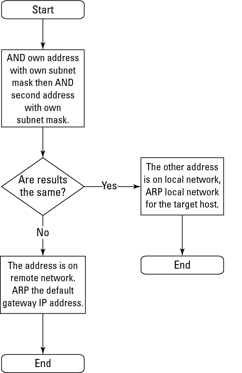
To understand the ARP process, examine Figure 3-1, which is the logic tree followed for ARP-related network communications. Any communication session always has two IP addresses of importance:
• Your IP address
• The IP address of the device you are trying to communicate with
As you see in the next section “The logical AND,” these two addresses and your subnet mask determine whether the device you are trying to talk to is on the same network.
The logical AND
In Book I, Chapter 3, I introduce you to a logic gate. One of those gates was an AND gate, and it is this AND operation that determines whether the other device is local or remote. Just as when you perform an ADD operation, dubbed ADDing, when you perform an AND operation, you are ANDing. To determine whether two IP addresses are on the same network segment (your IP address and a second IP address), follow this general process:
1. Perform an AND calculation with your IP address and your subnet mask.
2. Perform an AND calculation with the second IP address and your subnet mask.
3. Compare the two results.
Each AND calculation results in numbers that can be compared visually to see whether they are equal. If the two results are the same, the two devices are on the same network segment. Conversely, if the results differ, the two devices are on different network segments. When the devices are on different network segments, use a router to allow communication between the two devices.
Figure 3-1: The ARP decision-making process.
The rest of this section explains the exact process of the AND logical operation and shows you this operation in action, including the result of performing the AND operation with your IP address and your subnet mask.
Start by taking a closer look at the AND operation. AND is an operator in a logic, or Boolean, calculation. (You can find out more about logical operators in Book I, Chapter 3.) Most logic operators work only when dealing with binary values because you can have only two states — either 0 or 1. Table 3-1 shows the AND results based on two values. The table shows the four possible calculations when using two 1-bit numbers.
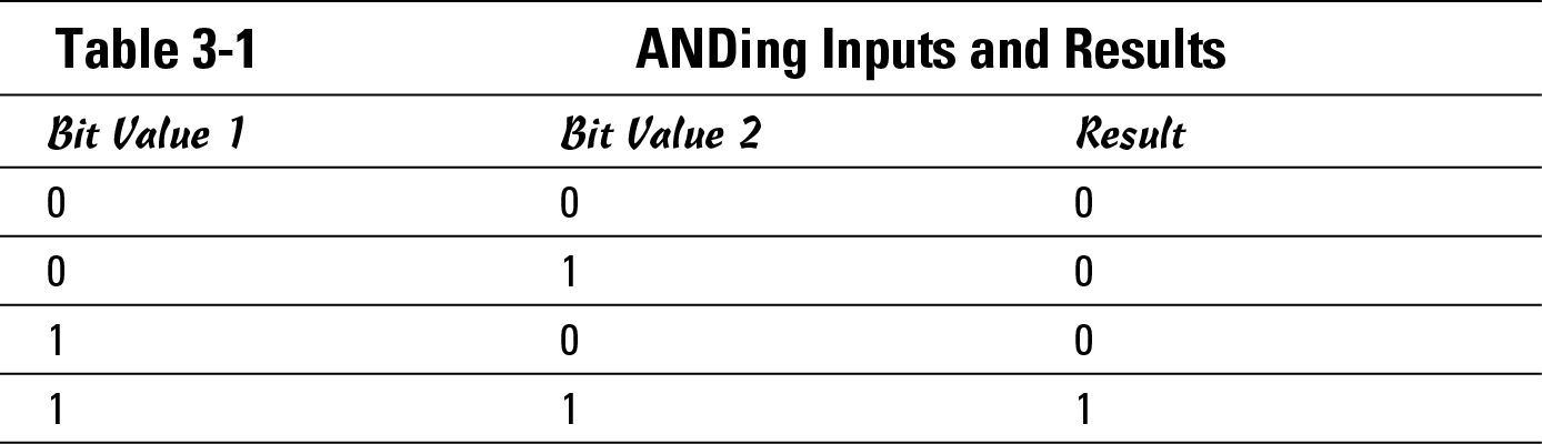
Notice that if you have two 1s, or all 1s in the calculation, the result is a 1. And if you have any 0s in your calculation, the result is 0.
Take this a step further and compare two IP addresses that exist on the same network, as shown in Tables 3-2 and 3-3. Table 3-2 works with 192.168.1.54/24, and Table 3-3 works with 192.168.1.129. If you view the addresses from the perspective that 192.168.1.54/24 is the address of your computer, you know what your IP address and subnet mask is. The address of 192.168.1.129 represents another host (I call it the target host) on an unknown network segment (because you do not know whether it is your local network segment or some other network segment). However, these tables prove that 192.168.1.129 and 192.168.1.54/24 are on the same network segment. You know the address you want to connect to, 192.168.1.129, but because it is a remote computer (as opposed to your computer), you do not know what subnet mask that computer is using. Because you cannot know the other subnet mask, the ARP process conducts both AND operations using your subnet mask.
Table 3-2 performs the AND operation with your IP address and your subnet mask. This first step is to convert your address and your subnet mask to binary, and then conduct the AND operation on each bit of the binary address and subnet mask, in columns through the number. Whether you move left to right (or right to left) through the number does not matter; unlike mathematical operations, there are no numbers to carry from one column to the next. For the first four bits in the first octet, the operation is 1 AND 1 is 1, 1 AND 1 is 1, 0 AND 1 is 0, 0 AND 1 is 0. Follow this operation through to the end of the last octet.
![]() In Chapter 1 of this minibook, I mention that /24 defines the subnet mask to be 24 bits, or 255.255.255.0.
In Chapter 1 of this minibook, I mention that /24 defines the subnet mask to be 24 bits, or 255.255.255.0.

Table 3-3 performs the same AND operation, but you are now working with the IP address of the target host and your subnet mask. You follow the same operations, first convert the address and your subnet mask to binary; then bit by bit, move through the number and perform an AND operation on each set of bits. The results are in the last row of the table.
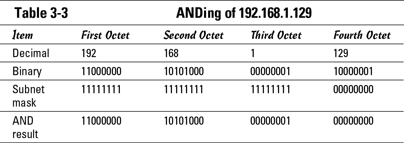
If you compare these AND results from the last row in Tables 3-2 and 3-3, note that the results are the same (11000000.10101000.00000001.00000000). And because these results are the same, the two addresses are on the same network or network segment.
Take this a step further and compare the two IP addresses that exist on different networks, as shown in Tables 3-4 and 3-5. Table 3-4 works with 192.168.1.54/24, which is your address. This table will perform the same calculation as Table 3-2, but I wanted to keep them next to each other in the book to make it easier for you to follow along. Remember, this table uses your address and your subnet mask.
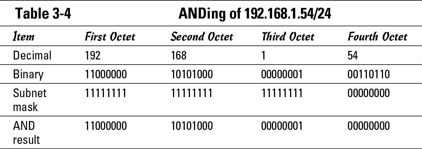
Table 3-5 works with 10.45.11.54, which represents the IP address of the target host on a network, and at this point, you do not know whether that network is your network or another network segment. You know the address you are attempting to communicate with and you know your subnet mask, so these are the numbers you use in the AND operation.
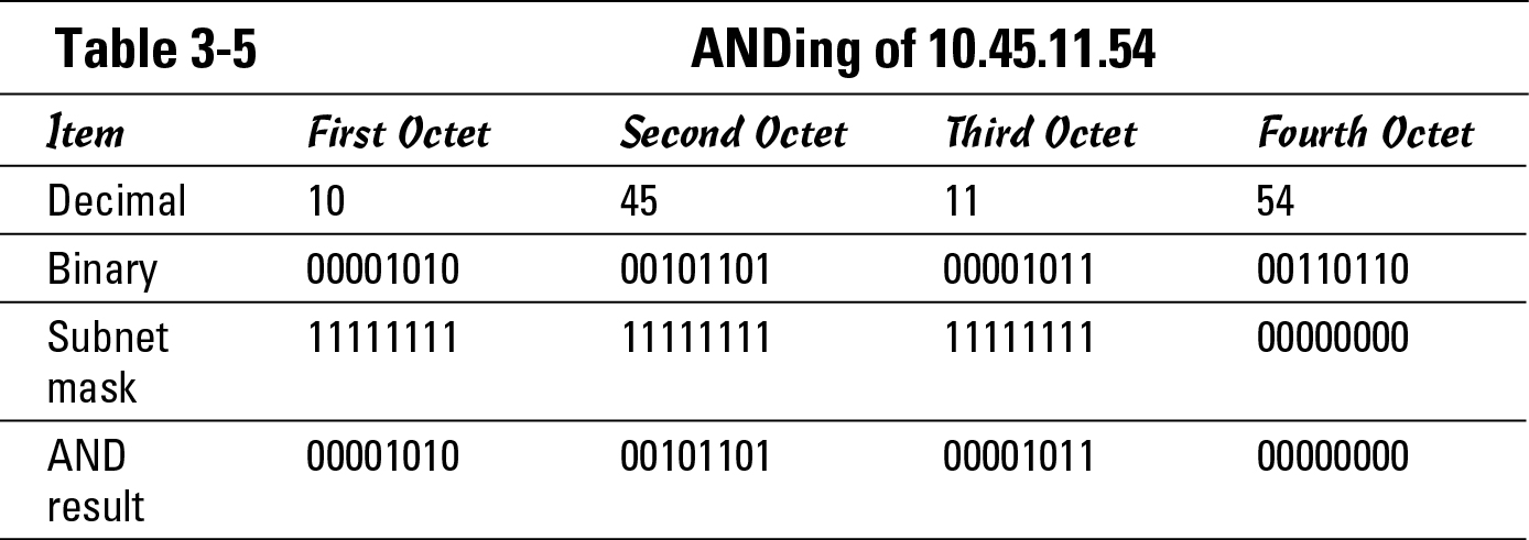
When you compare the results found in the last row of Tables 3-4 and 3-5, you have 11000000. 10101000.00000001.00000000 from Table 3-4 and 00001010.00101101.00001011.00000000 from Table 3-5. These two numbers are not the same. Because the results do not match, these two addresses are on different networks.
Using ARP
After you identify whether the target host is local to your network or a remote network, I show the next step the ARP process takes. Refer to Figure 3-1 to see that if the target computer is your local network, your computer will use the ARP protocol and request the MAC address for the target host’s IP address. After your computer has the MAC address, it can send data to the target host.
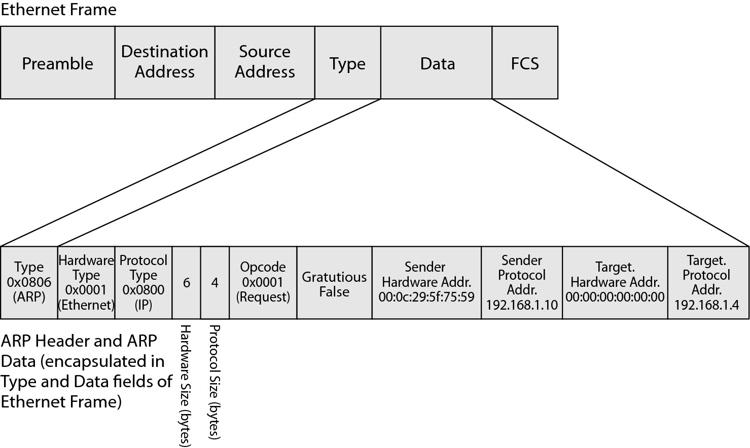
So what exactly is ARP? Start by taking that right down to the OSI model. Figure 3-2 shows the field breakdown of the entire Ethernet frame, which is the entire piece of data transferred at the network level. (See Book I, Chapter 4.) The ARP-specific information is found within that Ethernet frame in the Type and Data fields. Figure 3-2 shows sample information in the ARP header and Data fields. Here is a list of the header fields and what type of information you can expect to see:
• Type: Stores the Type number of the protocol data that is found in the Data field of the Ethernet frame. I have shown this in the ARP data, but this field is actually part of the Ethernet frame structure. For most IP data, the type is 0x0800, but ARP has its own type, 0x0806. This means that even at the network interface layer of the IP network model, the data found in this packet is identified as ARP data.
• Hardware Type: Within the ARP header, this identifies the physical hardware classification of the network, such as Ethernet or Token Ring. Because most networks are Ethernet networks, you can expect to see a 0x0001 value in this field.
• Protocol Type: Identifies the Internet layer protocol, typically IP, that is in use. Expect to see a value of 0x0800, which stands for IP, in this field.
• Hardware Size: The size (in bytes) of the hardware or MAC address. In Book I, Chapter 4, a MAC address is 48 bits in length, which is equal to 6 bytes.
• Protocol Size: The size (in bytes) of the protocol or IP address. In Book I, Chapter 4, an IP address is a 32-bit number, which is equal to 4 bytes.
• Opcode: The opcode, or operation code, specifies what type of ARP packet is being sent. You can expect to see Request (0x0001) and Reply (0x0002).
• Gratuitous: Some hosts may send ARP reply to announce their IP and MAC addresses. If they send this type of ARP packet, this field is set to True. This type of ARP announcement is a Gratuitous ARP because it is typically not needed.
• Sender Hardware Address: The hardware address of the sending host, for an Ethernet network is the MAC address of network card. Every ARP packet contains the hardware address of the sending host.
• Sender Protocol Address: The protocol address of the sending host. For IP networks, this is the IP address. Every ARP packet contains the IP address of the sending host.
• Target Hardware Address: The hardware address of the target host. As with the Sender Hardware Address field, this field contains the MAC address of the target host. In an ART request, this field is the hardware broadcast address (FF:FF:FF:FF:FF:FF for Ethernet) because the purpose of the ART request is to locate the MAC address of another host on the network. In an ARP reply, this field contains the MAC address of the host that sent the original ART request.
• Target Protocol Address: The protocol (or IP) address of the target host. In an ART request, this field contains the IP address of the host for whom you attempt to locate a MAC address. In an ARP reply, this field contains the IP address of the host that sent the original ART request.
Figure 3-2: The ARP network frame.
ARP requests for local hosts
For local hosts (hosts on your network segment), an ARP request starts with some type of network communication request between the two computers. This could be ping, the establishment of a Transmission Control Protocol (TCP) session, or a User Diagram Protocol (UDP) session. Regardless of the reason, the net result is the following process:
1. The first host contacts another host.
The first host performs an AND operation on its address and subnet mask, as well as the second host’s address and its subnet mask, as I describe in the earlier section “The logical AND.” This determines that the IP addresses belong on the same network, so the second host should be on the same network segment.
2. This request goes down through the OSI layers until it hits the network layer (or the Internet layer in the IP network model). At that layer, the target IP address must to be matched to a MAC or hardware address.
3. The decision tree in Figure 3-1 is followed.
The very first thing that is checked is the local ARP cache.
The following section takes a closer look at what happens during that process.
![]() By default, items will not remain the ARP cache of a computer for longer than ten minutes but are in the ARP cache of a Cisco network device for four hours. On a computer, the ARP cache contains only recent hosts that have had communication sessions. You examine how to review and manipulate the ARP cache on a computer later in this chapter in the section “Troubleshooting with ARP.”
By default, items will not remain the ARP cache of a computer for longer than ten minutes but are in the ARP cache of a Cisco network device for four hours. On a computer, the ARP cache contains only recent hosts that have had communication sessions. You examine how to review and manipulate the ARP cache on a computer later in this chapter in the section “Troubleshooting with ARP.”
4. If the IP address you are trying to communicate with is not in the ARP cache, the address needs to be resolved.
Figure 3-3 shows the first step in this process. Notice that the target hardware address is the broadcast address for Ethernet.
5. The data request is placed on hold until the address is resolved and an ARP request is generated and sent onto the network.
All ARP requests have the same basic format: two hardware (or MAC) addresses and two protocol (or IP) addresses (source and target).
The data request includes the sending host’s MAC and IP information as well as the IP address of the targeted host. The opcode for this type of packet is 0x0001, denoting that this is a request.
Figure 3-3: Sending an initial ARP packet.

6. The packet is sent to the local hardware broadcast address, so every computer on the local network segment sees that frame and processes it.
Upon processing the frame and reading the packet information, most computers discard the data because their IP address does not match the one being searched.
7. If by chance, a host does have that address, it records the source MAC and IP address in its own ARP cache, knowing that if someone wants to talk to it, it will likely need to send data shortly, so it then builds its own ARP packet in response.
The response ARP packet has an opcode of 0x0002, denoting that it is a reply. The ARP reply’s structure, looks the same as the ARP request, except that all four address fields are filled out and completed. Logically, it uses its address as the sender address and the sender of ARP request as the target. Figure 3-4 gives you an idea of what this looks like.
Figure 3-4: Sending an ARP reply packet.

8. With the response sent, the original host sees a frame on the local network segment that is addressed directly to its MAC address; it opens that frame and processes the ARP packet.
The original host then knows the target MAC it needs to send its data to.
9. The original host adds the ARP information to its ARP cache and then releases the data it had placed on hold, sending it to the target MAC address over the local network segment.
ARP requests for remote hosts
The process from the preceding section is a little different if the targeted host is not on the local subnet. Figure 3-5 shows you a rough overview of that process, which starts with an ARP to the default gateway that triggers a series of ARPs from that gateway or router through all the routers that connect these two hosts. For simplicity, the figure shows only one router, but there could be any number of routers between these two hosts. The following steps explain this process:
Figure 3-5: The ARP request process for remote hosts.

1. The first host has data to send to the second host, the data is placed on hold, and two AND operations are performed.
One operation uses the IP address and subnet mask of the first host, and the second uses the IP address of the second host and the subnet mask of the first host.
The result is that two hosts are on separate network segments.
2. A communication session needs to be established through the network routers.
The closest router that is known is the default gateway (192.168.1.1). To be able to send data through the router, the first host needs to know the MAC address of the router. The host checks the ARP cache, and if the MAC address for 192.168.1.1 is not there, it sends an ARP request for the 192.168.1.1 IP address.
3. After the first host gets the ARP reply from the router, the first host releases the data that needs sent to the second host.
Because the data is going to a host on a remote network segment, the data is sent through the router.
4. The data arrives at the router, and the router determines whether the second host is local to any of its attached network interfaces or network segments.
5. If the second host is on a connected network segment, the router can send an ARP request looking for the MAC address of the host with the 10.45.11.54 IP address; however, if the second host is not on a connected network segment, the router needs to send the ARP request to another router that the router thinks is closer to the second host.
In this case, the second host is directly attached to the required network segment, and the router would know that by going through the AND operation for all its network interfaces and the IP address of the second host.
6. After the router identifies the network connection or network interface where the router expects to find the second host, the router sends the ARP request to that network segment.
7. The second host, as shown in Figure 3-6, now knows that another host is attempting to communicate with it. The second host records the IP address and MAC information for the router in its ARP cache.
However, the second host does not know the first host’s MAC address; it never needs to know this info.
8. The second host sends the ARP reply back to the router on its network.
9. After the router receives the ARP reply from the second host, it knows how to get the pending data to the second host, and that data is then sent over the shared network segment to the second host.
Figure 3-6:
The ARP reply process for remote hosts.

Troubleshooting with ARP
This ARP process happens very fast and is built into the lowest levels of the networking protocol. In the end, the process appears to be almost transparent, but knowing how it works can greatly help with network troubleshooting. When I look at the address database on any device or host on the network, I only ever see systems on the local network segment listed in the ARP cache.
Many troubleshooting tools are available on most workstations, and although they vary somewhat between operating systems, arp is one of the standard commands. In this section, you see how to use the arp command on a Windows-based computer, but the main options for this command work the same regardless of the operating system.
Checking out arp command options
Running arp without any options displays help for the arp command, which is as follows:
C:>arp
Displays and modifies the IP-to-Physical address translation tables used by
address resolution protocol (ARP).
ARP -s inet_addr eth_addr [if_addr]
ARP -d inet_addr [if_addr]
ARP -a [inet_addr] [-N if_addr]
-a Displays current ARP entries by interrogating the current
protocol data. If inet_addr is specified, the IP and Physical
addresses for only the specified computer are displayed. If
more than one network interface uses ARP, entries for each ARP
table are displayed.
-g Same as -a.
inet_addr Specifies an internet address.
-N if_addr Displays the ARP entries for the network interface specified
by if_addr.
-d Deletes the host specified by inet_addr. inet_addr may be
wildcarded with * to delete all hosts.
-s Adds the host and associates the Internet address inet_addr
with the Physical address eth_addr. The Physical address is
given as 6 hexadecimal bytes separated by hyphens. The entry
is permanent.
eth_addr Specifies a physical address.
if_addr If present, this specifies the Internet address of the
interface whose address translation table should be modified.
If not present, the first applicable interface will be used.
Example:
> arp -s 157.55.85.212 00-aa-00-62-c6-09 .... Adds a static entry.
> arp -a .... Displays the arp table.
Looking through your ARP cache with arp -a
Take a look at the most-used arp command, which is arp –a. Issuing this command displays the contents of your ARP cache, which is sometimes critical when troubleshooting local communications. The output from this command looks like the following:
C:>arp -a
Interface: 192.168.1.137 --- 0x60005
Internet Address Physical Address Type
192.168.1.254 00-1d-7e-f8-23-d6 dynamic
Interface: 10.42.200.22 --- 0x200007
Internet Address Physical Address Type
10.42.0.3 00-11-22-33-44-55 dynamic
10.42.0.4 00-11-22-33-44-55 dynamic
This shows you the IP addresses that are found in the ARP cache for each network interface in your computer. In this case, there are two network interfaces, with a combined total of three addresses that are cached. Now, if you want to get another entry into the cache, you simply need to attempt to communicate with another device on the network. A simple ping command would suffice for this, but any network request would work. After attempting this with two other addresses (192.168.1.5 and 192.168.1.30), those systems appear in the ARP cache:
C:>arp -a
Interface: 192.168.1.137 --- 0x60005
Internet Address Physical Address Type
192.168.1.5 00-22-15-ba-93-1c dynamic
192.168.1.30 20-cf-30-3a-f7-c9 dynamic
192.168.1.254 00-1d-7e-f8-23-d6 dynamic
![]() These systems are listed as dynamic, which means that they were added and removed automatically. After waiting for two minutes, the systems time out of the ARP cache, and the cache will not include the MAC addresses of those other two systems. If there has been communication with that host over that two-minute period, it will remain in the cache for up to ten minutes.
These systems are listed as dynamic, which means that they were added and removed automatically. After waiting for two minutes, the systems time out of the ARP cache, and the cache will not include the MAC addresses of those other two systems. If there has been communication with that host over that two-minute period, it will remain in the cache for up to ten minutes.
Adding a static ARP entry
You may rarely want to add a static ARP entry. The static ARP entry is a permanent (until you delete it) entry into your ARP cache. One reason you may want to add static ARP entries is if you have two hosts that communicate with each other constantly throughout the day; by adding static ARP entries for both systems in each other’s ARP cache, you reduce some network overhead, in the form of ARP requests and ARP replies. The additional management work you need to do in adding and maintaining static ARP cache entries usually exceeds the network bandwidth that you save because ARP traffic consumes very little bandwidth. To add a static ARP cache entry, simply use a command like this:
C:>arp –s 192.168.1.30 20-cf-30-3a-f7-c9
This command creates a static entry in your ARP cache, so to start a communication session with the host that has a 192.168.1.30 IP address, you do not need to start the process with an ARP request; you already know the target host’s MAC address. If a similar ARP entry has not been added to the target host, the target host needs to send an ARP request to your computer to find out your MAC address.
After adding the static ARP entry, the ARP cache on your computer looks like this (notice the static entry that has been created):
C:>arp -a
Interface: 192.168.1.137 --- 0x60005
Internet Address Physical Address Type
192.168.1.30 20-cf-30-3a-f7-c9 static
192.168.1.254 00-1d-7e-f8-23-d6 dynamic
Communication with the host at 192.168.1.30 would work fine until the MAC address of the target computer changes, which could be because of a network card being changed or some other operation that changes the MAC address. When this happens, you need to delete the invalid ARP entry with an arp -d command, such as arp -d 192.168.1.30.
If you are using a Cicso router, it will also have an option to examine your ARP information. Connect to your Cisco router and enter Privileged EXEC mode. From here, you can run the command show arp to display your current ARP cache:
Router#show arp
Protocol Address Age (min) Hardware Addr Type Interface
Internet 192.168.1.1 - 0005.32af.8d72 ARPA Ethernet0
The preceding code shows that only the router’s own information is in the ARP cache, and thus that there have not been any other local devices talking to this router. Note the dash in the Age column, which indicates the age of the entry. The hyphen denotes that this entry will not age-out of the cache. If your router has been routing traffic for several computers, the ARP cache looks like this:
Router#show arp
Protocol Address Age (min) Hardware Addr Type Interface
Internet 192.168.1.8 0 000c.2960.4479 ARPA Ethernet0
Internet 192.168.1.1 - 0005.32af.8d72 ARPA Ethernet0
Internet 192.168.1.3 2 0021.2f31.0c64 ARPA Ethernet0
Internet 192.168.1.5 13 0022.15ba.931c ARPA Ethernet0
Internet 192.168.1.254 1 001d.7ef8.23d6 ARPA Ethernet0
Unlike Windows workstations, which keep ARP entries for a maximum of ten minutes, the ARP entry on a Cisco router remains in the cache for four hours (240 minutes), which is not uncommon because routers tend to spend most of their time dealing with the same hosts. Each time there is a communication session with that device, the counter is reset to 0. A router is often configured as a default gateway for network devices, which is why they see the same hosts communicating with that for most of a day, and as long as those hosts keep sending data through the router, they will remain in the ARP cache. For a router connected to large network segments, this would result in a rather large ARP listing or ARP table. A large ARP table consumes more of the router’s memory, so the caching time (or age) that Cisco has chosen was the result of a tradeoff of memory consumed by the ARP cache versus ARP’s need for fresh MAC information.
Similar to the earlier discussion on using ARP for the workstation, there may be times when you want to specify a static ARP entry for a router. This can be done by entering Global Configuration mode. From that mode, the arp command looks like this:
Router(config)#arp 192.168.1.30 20cf.303a.f7c9 arpa
After typing that command, your ARP cache includes that IP-MAC address pair, which would not age-out of the cache. This can be seen by the dash in the Age column. Static ARP entries are not usually identified to an interface like the dynamic entries are.
Router#show arp
Protocol Address Age (min) Hardware Addr Type Interface
Internet 192.168.1.1 - 0005.32af.8d72 ARPA Ethernet0
Internet 192.168.1.30 - 20cf.303a.f7c9 ARPA
If you no longer need the entry, or if you need to change to something else, remove the original entry with the no arp command:
Router(config)#no arp 192.168.1.30
After removing the entry, you can re-run the show arp command to see that it has been removed from the table:
Router#show arp
Protocol Address Age (min) Hardware Addr Type Interface
Internet 192.168.1.1 - 0005.32af.8d72 ARPA Ethernet0
Seeing how ARP is useful
Now that you have seen the arp command in action, what does that tell you? Here are a few areas where you might find this command helpful:
• Cannot ping host on network: Using arp tells you whether the host is on the network but just not responding to the ping request. Some devices, such as firewalls, do not respond to any Internet Control Message Protocol (ICMP) echo packets. They are configured this way for enhanced security, but it does make it difficult when troubleshooting. So if you attempt a ping and then see the address in your ARP cache, you know that the device or host is alive on the network — from the IP layer, anyway.
• Cannot ping host on remote network: Using arp tells you whether you are connecting to your default gateway properly. If you attempt to ping that remote system, your host should immediately identify the other host as a remote system and send an ARP request for the IP address of your default gateway or a local router. By checking your ARP cache, you can find your router in the list of known address pairs. If the router does not appear in the ARP table, the problem may be with the router not being available, or perhaps an error with your subnet mask. And if your subnet mask is wrong, you might think that there are more systems on your local network segment than there really are.
• Sporadic communication: Using arp tells you the hardware address that you are seeing. You can check the configuration of the target host to find out its hardware address and then verify what you are seeing in your ARP cache. If not, you might have a duplicate IP address on your network. The good thing is that you now know the MAC address of the duplicated computer, you can search for that MAC address on your network. Be aware, when you have a duplicate IP address situation, the IP-MAC address pair in your ARP cache may toggle back and forth between the correct and wrong MAC addresses while the two hosts with that IP address fight for control.
Using Other Troubleshooting Tools
When troubleshooting networking connectivity, you can use other tools, either at the OS level or at the Cisco router or switch level. In this section, you see how to make use of some of these tools, including
• ping
• traceroute
• pathping
These tools can help you identify exactly where the source of the issue is.
ping
Ping’s name comes from usage in sonar in which a sound pulse (literally, a ping) is sent and then the response echo is listened for in reflected sound waves. The distance to the target is gauged by the amount of time that passes between the ping and the reflected echo. Just like with a sonar ping, IP ping is used to test whether another device exists on a connected network.
And like the other commands in this section, ping uses ICMP to test this connection. ICMP passes control messages between routers on the network. They include items, such as Source Quench (if someone is sending data faster than the router can process) and Echo Request and Echo Reply (which are used by ping).
From the Windows OS, the ping command generates this help information from the command line:
C:>ping
Usage: ping [-t] [-a] [-n count] [-l size] [-f] [-i TTL] [-v TOS]
[-r count] [-s count] [[-j host-list] | [-k host-list]]
[-w timeout] target_name
Options:
-t Ping the specified host until stopped.
To see statistics and continue - type Control-Break;
To stop - type Control-C.
-a Resolve addresses to hostnames.
-n count Number of echo requests to send.
-l size Send buffer size.
-f Set Don’t Fragment flag in packet.
-i TTL Time To Live.
-v TOS Type Of Service.
-r count Record route for count hops.
-s count Timestamp for count hops.
-j host-list Loose source route along host-list.
-k host-list Strict source route along host-list.
-w timeout Timeout in milliseconds to wait for each reply.
To test for connectivity, use ping with the IP address of the device that you want to test for connectivity. Here is an example, connecting to www.cisco.com:
C:>ping www.cisco.com
Pinging origin-www.cisco.com [72.163.4.161] with 32 bytes of data:
Reply from 72.163.4.161: bytes=32 time=74ms TTL=105
Reply from 72.163.4.161: bytes=32 time=97ms TTL=105
Reply from 72.163.4.161: bytes=32 time=71ms TTL=105
Reply from 72.163.4.161: bytes=32 time=89ms TTL=105
Ping statistics for 72.163.4.161:
Packets: Sent = 4, Received = 4, Lost = 0 (0% loss),
Approximate round trip times in milli-seconds:
Minimum = 71ms, Maximum = 97ms, Average = 82ms
Note a few things from this response. For starters, each response is sent from a remote system and has nothing to do with the system you sent it from. In this example, I started with a ping to a computer name; so, for this to work right from the start, I had to rely on a Domain Name Server (DNS) to resolve that name to a proper IP address, which worked in my case. The Echo Request then went to the listed IP address. Four requests were sent, and the time for each Echo Response was listed.
Also, note the Time to Live (TTL). Every IP packet that is sent on the network has a TTL. The TTL on a packet is reduced by one as it is handled by each router on the network. When this value is set to 0, the router that is handling it at the time discards the packet and sends an ICMP message back to the originating IP address, stating that the packet Expired in transit. The TTL starts from one of the well-known binary numbers, such as 32, 64, 128, or 256. Because most devices on the Internet are usually less than 15 router hops from each other, I suggest that the server at Cisco starts its TTL 128, which would put it about 23 routers away from me. (I take another look at that when I discuss traceroute.)
Here are some error messages that you likely encounter using ping:
• TTL Expired in Transit: This rather uncommon error message means that the data packet had its TTL set to 0 during transmission. Typically, this happens only if have a routing loop of some sort on the network, and you are trying to get to an address forwarded in the loop. For example, if RouterA and RouterB have each other set as the gateway of last resort or default gateway, and you ping an address that does not exist, each router will say, “I do not know that address; here, you take it” — and this will happen until the TTL hits 0. You will see a response like Reply from 24.215.102.133: TTL expired in transit. This is the reason why this TTL process was implemented in the IP protocol: to prevent loops allowing packets to forever loop around the Internet.
• Destination Host Unreachable: When you see this message, it means that for some reason, the host is not deemed reachable by one of the routers or devices on path. This is different from the upcoming error message Request Timed Out in that you are being told specifically that the device cannot be contacted. Typically, this message comes from a router that is directly attached to the network segment that should have the host. It is telling you that you have reached the remote network segment, but there is no host there.
• Destination Net Unreachable: Like the Destination Host Unreachable error message, this message tells you that the network on which the host you are attempting to connect is not reachable. Typically, this message will come from a router along the path to the destination network. This would be a router that should be able to directly pass data to that segment — but it cannot. This sometimes occurs when you are guessing at remote segments based on a known pattern or network numbering scheme, but the segment you are attempting to contact does not actually exist, or you were given the wrong IP information.
An example of a number scheme might be the case of having five regional offices, New York, Chicago, Los Angeles, Houston, and Miami. I know the network IDs for New York, Chicago, and Los Angeles are 10.10.0.0/16, 10.20.0.0/16, and 10.30.0.0/16. That may lead me to believe that Houston and Miami would be 10.40.0.0/16 and 10.50.0.0/16, respectively. I also know that office routers start at 1, so if the New York router is 10.10.0.1, the Houston router should be 10.40.0.1 or 10.50.0.1. If the Houston network ID is actually 10.70.0.0/16, and there are not actual 10.40.0.0/16 or 10.50.0.0/16 networks, my attempt to ping the Houston network using 10.40.0.1 would yield me a Destination Net Unreachable error message.
• Request Timed Out: When you receive this error message, it means that the packet was sent, but no response was ever received. This is the most common error message. Unfortunately, it does not tell you exactly what the issue is; rather, you did not get a response. The problem could be with your configuration, missing a default gateway or a router, or an incorrect subnet mask, so you are looking for other hosts on a remote segment, or expecting them to be on the local network segment when they are not supposed to be. Your Echo Request may be making it to the target host, but the target host is not configured correctly, so the target host cannot send a message back to you. The problem could also be with the address that you are trying to contact, in that it is not correct or changed without your knowing the new address.
The problem could also be a firewall issue, which may be blocking ICMP data yet allowing other data through. Finally, it could just be that the target host is too busy to respond. Even though an ICMP response is quick and easy, if a host is too busy, it will drop these packets because, after all, they are simply diagnostic messages and not really important.
• Unknown Host: This is not an ICMP error, but rather ping reporting a DNS error.
With your Windows-based ping, here are some additional options to examine. The most common ones are
• ping -t www.cisco.com: Ping until stopped with a break (Ctrl+C). This is useful when you are making configuration changes and want to see when they take effect, or if you are waiting for a system to reboot.
• ping -n 15 www.cisco.com: Ping for a specific number attempts, rather than the default four attempts.
• ping -l 3000 www.cisco.com: Specifies to send a larger payload. With Windows computers, 32 bytes are sent by default, and that is a portion of the alphabet repeated as many times as necessary. If you want to see the largest block of data you can send between two hosts without having IP fragment the packet, you can adjust the size and add the -f option. If the packet is fragmented, you will get a response like Packet needs to be fragmented but DF set.
• ping -r 9 www.google.ca: Specifies that you should list the routers along the path, up to a maximum of nine routers. This is an alternative to using traceroute (discussed in the next section), and it is interesting when compared with traceroute because it typically shows the IP addresses of the routers facing the target rather than you. The output of this command looks like the following:
Reply from 74.125.226.81: bytes=32 time=51ms TTL=55
Route: 71.7.162.168 ->
24.215.102.134 ->
24.215.102.6 ->
24.215.102.10 ->
24.215.101.9 ->
216.239.49.219 ->
64.233.175.99 ->
10.252.162.94 ->
74.125.226.81
• ping -i 10 www.cisco.com: Sets the TTL flag on your outgoing ICMP Echo Request. This means that after the TTL hits 0, you get the error message about the packet expiring in transit. For your internal network, you may know how many routers you should pass through between two points, and using this option can let you closely identify the exact location of looping errors because you see what router expired the packet. With this option, you get either the expired message or a response from the target.
![]() When you get the reply, it lists the TTL set by the remote host, and not the one you specified on your outgoing request.
When you get the reply, it lists the TTL set by the remote host, and not the one you specified on your outgoing request.
• ping -w 4000 www.wiley.com: Sets the amount of time to wait for a reply before reporting that the Request timed out. The default time to wait is four seconds, which is sufficient for most well-connected networks. Some slow links, such as cellular or satellite connections, may require longer wait times.
If you are using your Cisco router, enter Privileged EXEC mode to gain access to the ping command. Here is an example of the output:
Router#ping www.cisco.com
Translating “www.cisco.com”...domain server (192.168.1.254) [OK]
Type escape sequence to abort.
Sending 5, 100-byte ICMP Echos to 72.163.4.161, timeout is 2 seconds:
!!!!!
Success rate is 100 percent (5/5), round-trip min/avg/max = 72/79/92 ms
Notice the series of exclamation marks in the output; these identify successful responses from the remote host. The following shows the periods of unsuccessful echo attempts:
Router#ping www.wiley.com
Translating “www.wiley.com”...domain server (192.168.1.254) [OK]
Type escape sequence to abort.
Sending 5, 100-byte ICMP Echos to 208.215.179.146, timeout is 2 seconds:
.....
Success rate is 0 percent (0/5)
traceroute/tracert
Although using ping can tell you whether a host is up, all the firewalls that block ICMP requests can make it tough to tell whether you have a correct address that you are attempting to communicate with.
Enter traceroute, which displays the routers that exist between you and the remote host that you are attempting to communicate with. Because this information is not found in the ICMP data, it ingeniously makes use of the expired TTL functionality of IP. traceroute sends three ICMP requests to the destination, but sets the TTL of the ICMP request to 1, which is set to 0 by the first router. The ICMP message that it receives telling it that the packet expired includes the routers address. It then sends three more requests with a TTL of one higher number until it successfully reaches the destination or hits 30 routers.
Although you use traceroute on a Cisco router and on a Linux computer, on a Windows computer, the traceroute command is shortened to the 8.3-naming convention as tracert.exe and has the following options:
C:>tracert.exe
Usage: tracert [-d] [-h maximum_hops] [-j host-list] [-w timeout] target_name
Options:
-d Do not resolve addresses to hostnames.
-h maximum_hops Maximum number of hops to search for target.
-j host-list Loose source route along host-list.
-w timeout Wait timeout milliseconds for each reply.
The basic traceroute command is something like this request to www.google.ca:
C:>tracert.exe www.google.ca
Tracing route to www.l.google.com [74.125.226.81]
over a maximum of 30 hops:
1 1 ms 1 ms 1 ms fw1.edtetz.net [192.168.1.254]
2 55 ms 23 ms 21 ms blk-7-160-1.eastlink.ca [71.7.160.1]
3 12 ms 25 ms 9 ms skvl-asr2.eastlink.ca [24.222.226.165]
4 27 ms 10 ms 11 ms ns-hlfx-dr002.eastlink.ca [24.215.102.133]
5 12 ms 33 ms 37 ms ns-hlfx-br002.eastlink.ca [24.215.102.5]
6 39 ms 16 ms 15 ms ns-hlfx-br001.eastlink.ca [24.215.102.9]
7 44 ms 38 ms 37 ms google.eastlink.ca [24.215.101.10]
8 37 ms 37 ms 34 ms 216.239.47.114
9 37 ms 49 ms 38 ms 64.233.175.98
10 50 ms 54 ms 39 ms 74.125.226.81
Trace complete.
In the following output, note that you see the time for each three responses at each router, with the * (on line 7) denoting a request that timed out. This lets you see if one router is overly busy, as it would have substantially higher response times. By default, the command also performs a reverse DNS lookup for each router IP address along the path. The DNS lookups provide you names for routers that have their names registered in DNS. The reverse DNS lookup function can be disabled with the –d option as shown here:
C:>tracert.exe -d www.google.ca
Tracing route to www.l.google.com [74.125.226.81]
over a maximum of 30 hops:
1 1 ms 1 ms 1 ms 192.168.1.254
2 29 ms 45 ms 15 ms 71.7.160.1
3 9 ms 26 ms 11 ms 24.222.226.165
4 9 ms 13 ms 9 ms 24.215.102.133
5 9 ms 13 ms 9 ms 24.215.102.5
6 15 ms 11 ms 31 ms 24.215.102.9
7 33 ms * 35 ms 24.215.101.10
8 71 ms 34 ms 33 ms 216.239.47.114
9 32 ms 36 ms 32 ms 64.233.175.98
10 34 ms 33 ms 36 ms 74.125.226.81
Trace complete.
Like with the ping command, you can also specify the maximum number of routers to pass through, as well as the amount of time to wait before failing the request packets.
If using a Cisco router, the traceroute command has a slightly different appearance to its output, but even though the format of the output is somewhat different, traceroute provides all the same information:
Router#traceroute www.google.ca
Translating “www.google.ca”...domain server (192.168.1.254) [OK]
Type escape sequence to abort.
Tracing the route to www.l.google.com (74.125.226.84)
1 fw1.edtetz.net (192.168.1.254) 4 msec 4 msec 0 msec
2 blk-7-160-1.eastlink.ca (71.7.160.1) 32 msec 28 msec 28 msec
3 skvl-asr2.eastlink.ca (24.222.226.165) 16 msec 12 msec 48 msec
4 ns-hlfx-dr002.eastlink.ca (24.215.102.133) 24 msec 28 msec 8 msec
5 ns-hlfx-br002.eastlink.ca (24.215.102.5) 8 msec 8 msec 8 msec
6 ns-hlfx-br001.eastlink.ca (24.215.102.9) 44 msec 24 msec 12 msec
7 google.eastlink.ca (24.215.101.10) 36 msec 36 msec 32 msec
8 216.239.47.114 36 msec 32 msec 36 msec
9 64.233.175.98 40 msec 32 msec 36 msec
10 www.l.google.com (74.125.226.84) 36 msec 48 msec 32 msec
If you encounter a firewall that blocks your ICMP requests, you will find that at some point, all further requests time out. If you do not want to wait for it to complete the default 30 hops, you can cancel the trace by pressing Ctrl+C on a Windows computer or Ctrl+Shift+6 twice for your Cisco router.
PathPing
PathPing is a Windows utility that mixes the standard ping and traceroute commands. PathPing is useful for locating sporadic errors that occur along a path between two devices. In essence, it sends multiple pings to each router along a path and then displays statistics on packet loss. You should note from the PathPing help info that many of the options are similar to the basic ping command:
C:>pathping
Usage: pathping [-g host-list] [-h maximum_hops] [-i address] [-n]
[-p period] [-q num_queries] [-w timeout] [-P] [-R] [-T]
[-4] [-6] target_name
Options:
-g host-list Loose source route along host-list.
-h maximum_hops Maximum number of hops to search for target.
-i address Use the specified source address.
-n Do not resolve addresses to hostnames.
-p period Wait period milliseconds between pings.
-q num_queries Number of queries per hop.
-w timeout Wait timeout milliseconds for each reply.
-P Test for RSVP PATH connectivity.
-R Test if each hop is RSVP aware.
-T Test connectivity to each hop with Layer-2 priority tags.
-4 Force using IPv4.
-6 Force using IPv6.
The following options should be of interest:
• -p: Reduces the load on devices by waiting briefly between ping requests. This is different from the -w option, which identifies how long to wait before failing a request. This is the delay between successive ICMP requests.
• -q: Specifies the number of pings per hop in the path. The default is 100.
The default output of pathping looks similar to the following request to www.google.ca:
C:>pathping -n www.google.ca
Tracing route to www.l.google.com [74.125.226.81]
over a maximum of 30 hops:
0 192.168.1.137
1 192.168.1.254
2 71.7.160.1
3 24.222.226.165
4 24.215.102.133
5 24.215.102.5
6 24.215.102.9
7 24.215.101.10
8 216.239.47.114
9 64.233.175.98
10 74.125.226.81
Computing statistics for 250 seconds...
Source to Here This Node/Link
Hop RTT Lost/Sent = Pct Lost/Sent = Pct Address
0 192.168.1.137
0/ 100 = 0% |
1 1ms 0/ 100 = 0% 0/ 100 = 0% 192.168.1.254
0/ 100 = 0% |
2 19ms 2/ 100 = 2% 2/ 100 = 2% 71.7.160.1
0/ 100 = 0% |
3 15ms 0/ 100 = 0% 0/ 100 = 0% 24.222.226.165
0/ 100 = 0% |
4 23ms 1/ 100 = 1% 1/ 100 = 1% 24.215.102.133
0/ 100 = 0% |
5 14ms 0/ 100 = 0% 0/ 100 = 0% 24.215.102.5
0/ 100 = 0% |
6 16ms 0/ 100 = 0% 0/ 100 = 0% 24.215.102.9
0/ 100 = 0% |
7 42ms 0/ 100 = 0% 0/ 100 = 0% 24.215.101.10
0/ 100 = 0% |
8 40ms 0/ 100 = 0% 0/ 100 = 0% 216.239.47.114
1/ 100 = 1% |
9 39ms 1/ 100 = 1% 0/ 100 = 0% 64.233.175.98
0/ 100 = 0% |
10 38ms 1/ 100 = 1% 0/ 100 = 0% 74.125.226.81
Trace complete.
So to review that output, the pathping command starts with a summary of the path, and then provides your average response time and the number of packets that failed with their average for each node in the path. This process of multiple pings to each hop does take some time to generate.