
Chapter 5: Configuring Serial Connections and WAN Links
In This Chapter
![]() Working with the telephone company’s connection options
Working with the telephone company’s connection options
![]() Examining WAN technologies and connection options
Examining WAN technologies and connection options
![]() Setting up a basic serial connection to support a WAN connection
Setting up a basic serial connection to support a WAN connection
In Book IV, Chapter 1, I state that the key reason for using WANs is that you are using a network infrastructure you do not own. This chapter focuses on setting up Wide Area Network (WAN) links for your network. Many people use serial links to implement their WAN and Internet connections, but a moving trend is to implement fiber, Ethernet, or other connections directly at their routers. After discussing the types of links you can implement for WAN connections, I show you how to configure the serial connection.
After reading this chapter, you will appreciate the available WAN connection technologies, as well as how to configure them. I examine the role of the telephone company, and the general types of interfaces you can obtain from the telephone company. In each region, you are likely to find that the local telephone company has tried to implement newer and faster connection types, which, if you are in luck, means that just by plugging in a standard Ethernet-style connection, you can be up and running.
Finding Out Where the Telephone Company Fits In
You implement WAN links using whatever technologies your telephone company supports. You should be able to choose from many technologies. Although use of high-speed Internet connections and site-to-site VPN solutions is becoming popular, there are still many places outside major metropolitan areas where your choices will be quite limited.
Consider, for example, a connection between offices in New York to an office in Toronto: The traffic leaves the serial or WAN port on your router in Toronto and enters your service provider’s network. The traffic then traverses your service provider’s network — and possibly several service providers — until it arrives at the serial or WAN port on the New York router. When the traffic is on the service provider’s network, your traffic is isolated from other users’ traffic, whereas your Internet traffic is mixed together with everyone else’s traffic. Depending on the service provider, you can choose from various options or types of services.
Here are the three main options for connections offered by telephone companies:
• Circuit switching: A system that establishes a connection each time it has data to send, such as using a telephone.
• Leased lines: A system on which a connection that is always connected.
• Packet switching: A system on which the data on the service provider network may not always take the same path.
I discuss these options in the following sections.
Circuit switching
Circuit-switched solutions are characterized by connections that are established temporarily to send data. If you are using a circuit-switched solution, each time you send data to a location, you must establish the connection, send the data, and close the connection. This process is done automatically to addresses that are predefined by your telephone company and for which your router is configured. When you use circuit switching, your data always takes the same path and is guaranteed to arrive in order and intact. For these solutions, you contract the amount of bandwidth you require, and this bandwidth is yours, so you do not share it with other customers. Because you must pay for this bandwidth, this option may be appropriate for low-bandwidth solutions, but it becomes costly as bandwidth needs increase.
The main example of circuit-switched solutions is Integrated Services Digital Networks (ISDN), which is a solution that uses digital connections to carry either computer data or voice traffic. This solution uses two types of channels to carry data, B-channels and D-channels. A B-channel is capable of carrying data at a rate of 64 Kbps. A D-channel carries signaling data at a rate of 16 Kbps or 64 Kbps. Here are the main kinds of ISDN services In North America:
• Basic Rate Interface (BRI): The implementation of BRI supports two 64-Kbps B-channels to carry data at a combined rate of 128 Kbps. The signaling channel (D-channel) for BRI is 16 Kbps.
• Primary Rate Interface (PRI): The implementation of PRI supports up to 23 64-Kbps data channels (B-channels) to carry data at a combined rate up to 1.45 Mbps, while having one additional 64-Kbps D-channel carry the signaling information.
Leased lines
In a leased line solution, you purchase (or lease — surprise!) a permanent link while paying a monthly fee. In this case, you are not charged by the connection or the amount of data; instead, once you lease the line, you can send as much data over the link as the link will support. The permanent link is to your service provider’s network, and it is sometimes referred to as a point-to-point link.
Leased lines tend to have more available bandwidth than circuit switch solutions. The main examples of these solutions in North America are T1 and T3 links.
• T1 link: These links are made up of 24 channels that carry data at 64 Kbps, yielding a total bandwidth of 1.544 Mbps. Unlike PRI lines, they do not require a signaling channel. As mentioned, you can have up to 24 channels. When installed, the link will have all 24 channels, but when you pay for your service, you can pay for, or use, only a portion of this link. This option lowers your monthly cost and is called a fractional-T1 link.
• T3 link: These links offer additional channels. This option uses 28 T1 lines that are combined and yields a total bandwidth of 44.736 Mbps.
Packet switching
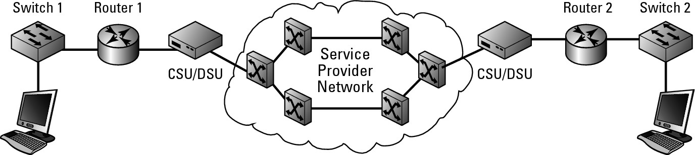
Packet switching differs substantially from the previous two options in that circuit-switched and leased lines will have all your data following a single path between two destinations. With packet switching, each packet or piece of data can take a different path from source to destination, as shown in Figure 5-1. Switching in this example is similar to switching on your LAN, except it is implemented on a much larger scale. When implementing a packet-switched solution, you usually work with a virtual circuit, which, like a physical circuit, establishes a connection between two points, but in this case it is a temporary connection. From the point of view of the devices on either end of the connection, there is only one router hop from one end of the connection to the other, but in reality they go through a huge switched network, being handled by many devices.
Some examples of this type of connection include:
• X.25: This represents one of the oldest technologies in use. As a packet-switched solution, it makes use of a packet assembler/disassembler (PAD) (which prepares data packets for transmission and processes them after transmission) device that is connected to the router’s serial port. Through this device, you are able to connect to the X.25 network and transfer your data at a rate of 2 Mbps.
• Frame relay: This is the replacement for X.25 and implements the same basic solution, but in a purely digital format and allows for speeds as fast as 50 Mbps. This connection can give you the same speed as a T3connection.
• Asynchronous Transfer Mode (ATM): A packet-switched network environment that differs greatly from the previous solutions in that it uses a fixed-length packet size referred to as a cell. A cell is the standard 53 bytes in size. ATM is a WAN technology capable of sending large, low-delay types of data (such as video) and can sustain a transfer rate of 622 Mbps. The small packet sizes are not a disadvantage — because other solutions need to keep checking for the end of a packet, and ATM eliminates this need by using the standard-sized frames. However, partial frames or cells will be padded with empty data.
Figure 5-1:
With a packet-switched network, data may take different paths.

Connecting Your Devices
For any connection type that you may choose to use, you must establish a connection between the service provider and your router. How you do so will vary based on the type of connection. In general, you will use serial ports or ISDN ports or implement a Channel Service Unit/Data Service Unit (CSU/DSU).
Serial ports
One of the main methods of connecting the router to your service provider’s network is via a serial port. Depending on your service provider connection, you may be provided with a CSU/DSU. The CSU/DSU serves the same purpose a modem (modulator/demodulator) in that it prepares your digital data to be sent over a telephone company network that may not be carrying a digital signal. These devices connect to the service provider connection, such as a T1 link, which is then connected to your router. Figure 5-2 illustrates this final link.
Figure 5-2: Implementing your WAN link using an external CSU/DSU.
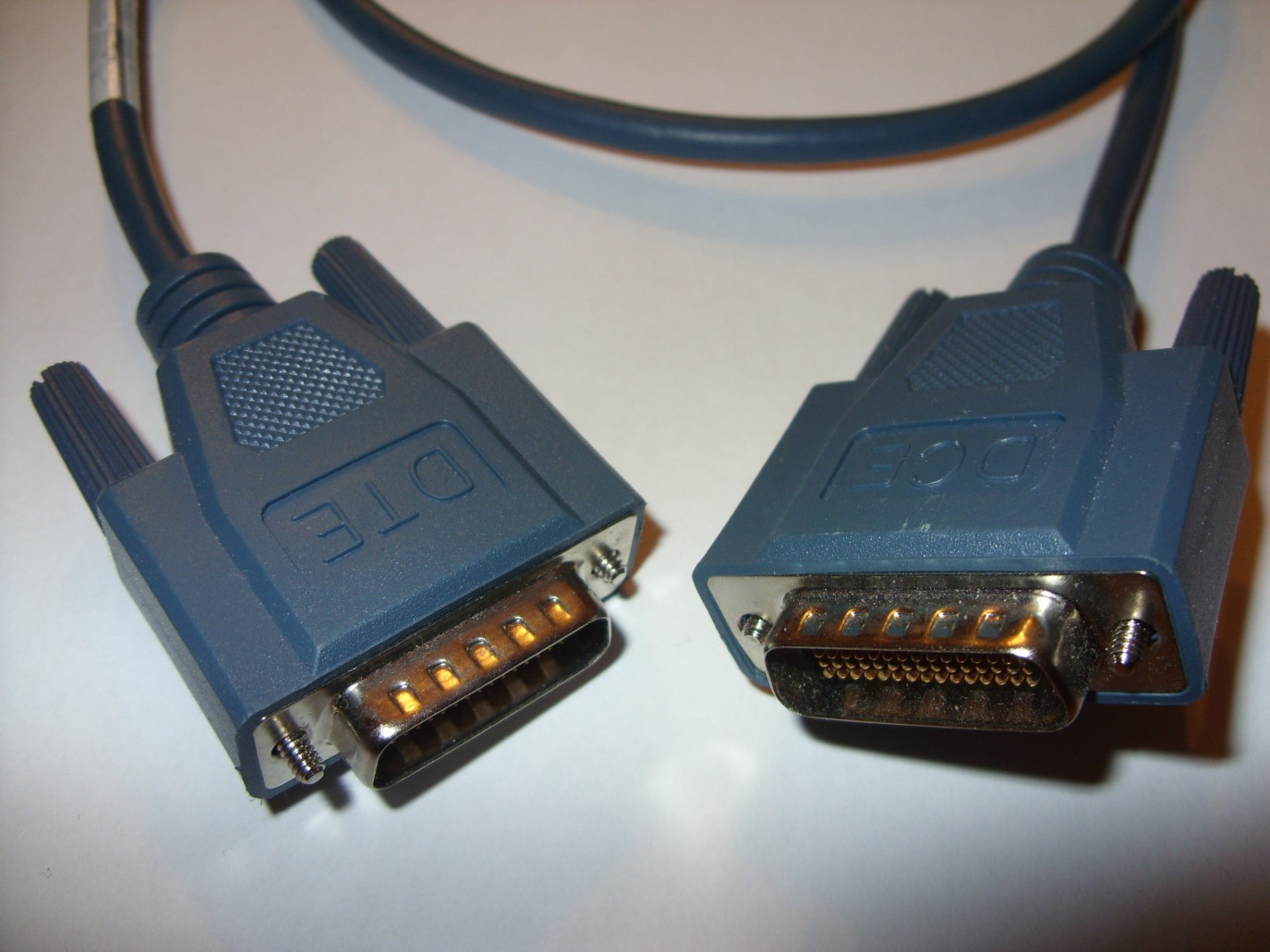
This breaks the connection into two types of devices: Data Terminal Equipment (DTE) which end user devices, and Data Communications Equipment (DCE) which are telephone company devices. In the computer world, a computer represents the DTE and a modem represents the DCE, but when dealing with your service provider, your router is the DTE, and the service provider’s communication devices are the DCE. So, the cable that connects to your router connects to the DTE, whereas the end of the cable that connects to the service provider’s equipment connects to the DCE. If you want to simulate a router-to-router serial connection for testing before deploying your network equipment, you can use a special serial cable (back-to-back serial cable), as shown in Figure 5-3, which is defined with two specific ends, for DTE and DCE.
Integrated CSU/DSU
Over the years, to reduce cost or complexity, it has become common for people to integrate the CSU/DSU components into their routers. Rather than having another bulky device sitting in your communications room, you can have the functionality of the CSU/DSU integrated into the circuitry of your router. The drawback is that if you decide to change the type of connection you have, you may need to change your router. Consequently, Cisco came up with the WAN Interface Card (WIC) port, which allows you to change the type of service provider connection you use at a minimum cost, allowing you to reuse your existing router.
Figure 5-3: A router-to-router back-to-back serial cable.
ISDN ports
With the prevalence of ISDN connections, Cisco has created and sold routers in a fixed configuration — rather than use WIC ports — that are preconfigured for ISDN environments. Your connectivity options are limited, but the price of these routers can represent an attractive price-point if you do not anticipate changing the connection types you use with your service provider.
Setting Up Your Serial Connection
Because I have discussed serial connections with some regularity, allow me to show you how to manage the connection from your Cisco device. For this example, you connect two routers by using a back-to-back cable or DTC-DTE cable, emulating a service provider connection between the two devices.
Configuring your serial connection
The basic configuration of a serial connection is no different than the other types of connections that are covered elsewhere in this book and covered in Book IV, Chapter 3. You enter Interface Configuration mode, set the IP address, and remove the shutdown command. Here is the code on Router1 to setup the required connection.
Router1>enable
Password:
Router1#config terminal
Router1(config)#interface serial 0
Router1(config-if)#ip address 24.0.0.1 255.0.0.0
Router1(config-if)#no shutdown
Router1(config-if)#exit
Router1(config)#exit
Configuring serial link protocols
With the basic IP configuration out of the way, you are ready to implement the serial link protocol or encapsulation protocol. You can choose from either High-Level Data Link Control (HDLC) or Point to Point Protocol (PPP), which are encapsulation protocols used to format data to send across the wire. When you are sending data over a serial link, your data is encapsulated using a serial link protocol. Both ends of the connections must support and implement the same protocol.
![]() HDLC does not support authentication. Because of this limitation and the compatibility issue, most people tend to implement PPP.
HDLC does not support authentication. Because of this limitation and the compatibility issue, most people tend to implement PPP.
Working with HDLC
HDLC is an ISO standard, but that has not stopped vendors from putting their own spin on the implementation, which means that its implementation is somewhat vendor-specific.
HDLC is the default serial link protocol implemented on Cisco routers, so with no other changes, this is the protocol you are likely to find in use. To ensure that the HDLC protocol to be used, and for you to see the command, run the following command:
Router1>enable
Password:
Router1#config terminal
Router1(config)#interface serial 0
Router1(config-if)#encapsulation hdlc
Router1(config-if)#exit
Router1(config)#exit
![]() Both ends of the serial link must use the same serial link protocol, so if one of your routers is using HDLC, it must be implemented on the other routers as well.
Both ends of the serial link must use the same serial link protocol, so if one of your routers is using HDLC, it must be implemented on the other routers as well.
Working with PPP
PPP is an open standard supported by many vendors, and it tends to be compatible among the vendors. PPP is also link type independent, meaning it can run over many physical serial link types, and supports the following two types of authentication protocol:
• PAP (Password Authentication Protocol): An authentication protocol that provides security by a username and a password that are transmitted in plain text when a connection is established between two hosts. This option is not the most secure one because it allows the authentication information to be captured by someone who may be capable of capturing data in-between your routers.
• CHAP (Challenge Handshake Authentication Protocol): This protocol does not send the authentication information in plain text. When implementing CHAP, a secret password is configured on both routers, the same secret at both ends. This secret is then encoded by a mathematical function called a hashing algorithm, and the resulting value is called the hash value. This hash value is sent over the network rather than the secret. A hash value is a unique value that can be duplicated only if a user knows the original secret value.
Router1>enable
Password:
Router1#config terminal
Router1(config)#username Router2 password mypass
Router1(config)#interface serial 0
Router1(config-if)#encapsulation ppp
Router1(config-if)#ppp authentication chap
Router1(config-if)#exit
Router1(config)#exit
Make note of the username created in the preceding commands; this username matches the hostname of the router that will be connecting to Router1. The password assigned to this account is the secret that will be used. On Router2, you need to create a Router1 account with a matching password.
Setting the clock rate
To finally get your system up and running, you need to set up the clock speed, which controls the speed at which data is sent over the connection in bits per second (bps). The DCE sets and controls the clock speed. So, in the case of a link from a service provider, the provider sets the clock speed, and when you connect to the external CSU/DSU, your serial port accepts the configuration. In the case of a back-to-back cable, one of the routers plays the role of the DCE, and that device sets the clock speed for the connection. If you are implementing the same type of layout in a lab, check the cable and identify the DCE side of the cable; then implement the clock speed with a command similar to the following:
Router1>enable
Password:
Router1#config terminal
Router1(config)#interface serial 0
Router1(config-if)#clock rate 64000
Router1(config-if)#exit
Router1(config)#exit
In this example, the clock rate is set at 64000 or 64 Kbps.
![]() To find the clock rates that are available on your router, type
To find the clock rates that are available on your router, type clock rate ? when in Interface Configuration mode on your serial connection, as shown in this command example:
Router1>enable
Password:
Router1#config terminal
Router1(config)#interface serial 0
Router1(config-if)#clock rate ?
1200
2400
4800
9600
19200
38400
56000
64000
72000
125000
<300-125000> Choose clockrate from list above
Router1(config-if)#end
Troubleshooting Serial Connections
As I repeat (repeatedly) in this book, to effectively identify and troubleshoot a problem, you must have the key information about the devices or services you are troubleshooting. Here, as in other chapters, I introduce some of the show and debug commands you can use to identify configuration or flow issues with serial connections.
Showing
The show command displays the configuration and status of your serial ports. In the following code, the items that stand out the most are the line protocols that are reported as down, meaning that the physical connection to the device at the other end of the connection is not established, as well as the encapsulation protocol that is in use, such as HDLC or PPP.
Router1# show interfaces serial 0
Serial0 is up, line protocol is down
Hardware is HD64570
Internet address is 24.0.0.1/8
MTU 1500 bytes, BW 1544 Kbit, DLY 20000 usec,
reliability 255/255, txload 1/255, rxload 1/255
Encapsulation HDLC, loopback not set
Keepalive set (10 sec)
Last input never, output 00:00:08, output hang never
Last clearing of “show interface” counters never
Input queue: 0/75/0/0 (size/max/drops/flushes); Total output drops: 0
Queueing strategy: weighted fair
Output queue: 0/1000/64/0 (size/max total/threshold/drops)
Conversations 0/2/256 (active/max active/max total)
Reserved Conversations 0/0 (allocated/max allocated)
Available Bandwidth 1158 kilobits/sec
5 minute input rate 0 bits/sec, 0 packets/sec
5 minute output rate 0 bits/sec, 0 packets/sec
0 packets input, 0 bytes, 0 no buffer
Received 0 broadcasts, 0 runts, 0 giants, 0 throttles
0 input errors, 0 CRC, 0 frame, 0 overrun, 0 ignored, 0 abort
21 packets output, 714 bytes, 0 underruns
0 output errors, 0 collisions, 12 interface resets
0 output buffer failures, 0 output buffers swapped out
After correcting the preceding problem — in this case, the clock speed was not set on the DCE device — the line protocol is reported as being up:
Router1#show interfaces serial 0
Serial0 is up, line protocol is up
Hardware is HD64570
Internet address is 24.0.0.1/8
MTU 1500 bytes, BW 1544 Kbit, DLY 20000 usec,
reliability 255/255, txload 1/255, rxload 1/255
Encapsulation HDLC, loopback not set
Keepalive set (10 sec)
Last input 00:00:09, output 00:00:08, output hang never
Last clearing of “show interface” counters never
Input queue: 0/75/0/0 (size/max/drops/flushes); Total output drops: 0
Queueing strategy: weighted fair
Output queue: 0/1000/64/0 (size/max total/threshold/drops)
Conversations 0/2/256 (active/max active/max total)
Reserved Conversations 0/0 (allocated/max allocated)
Available Bandwidth 1158 kilobits/sec
5 minute input rate 0 bits/sec, 0 packets/sec
5 minute output rate 0 bits/sec, 0 packets/sec
8 packets input, 1208 bytes, 0 no buffer
Received 8 broadcasts, 0 runts, 0 giants, 0 throttles
0 input errors, 0 CRC, 0 frame, 0 overrun, 0 ignored, 0 abort
91 packets output, 3282 bytes, 0 underruns
0 output errors, 0 collisions, 43 interface resets
0 output buffer failures, 0 output buffers swapped out
85 carrier transitions
DCD=up DSR=up DTR=up RTS=up CTS=up
After you know how to view current configuration information, take a look at the active connection and data going through the connection by using the debug command. You can choose from the following debug options. I focus on the interface option.
Router1#debug serial ?
interface Serial interface events
m32_dma Serial M32 DMA
mueslix Serial Mueslix
packet Serial network interface packets
revive Serial Revive
When you see the show command named Showing in the preceding section, you start with an issue with clock speed not being properly set on the DCE side of the connection. To see and diagnose a problem, I re-create the problem so that you can see what it would look like when troubleshooting with the debug command. When you have an issue with your connection, you can take a look at the information the debug command gives you about the serial interface. After the code example, I point out some information that you should be able to deduce.Router1#debug serial interface
Serial network interface debugging is on
Router1#
00:06:33: Serial0: HDLC myseq 32, mineseen 0, yourseen 0, line down
00:06:34: Serial0: attempting to restart
00:06:34: HD(0): Deasserting DSR, CTS and DCD
00:06:34: HD(0): Reset from 0x305CE4A
00:06:34: HD(0): Asserting DSR
00:06:34: HD(0): Asserting DCD and CTS
00:06:34: HD(0): Deasserting LTST
00:06:34: HD(0): Asserting DTR and RTS
00:06:43: Serial0: HDLC myseq 33, mineseen 0, yourseen 0, line down
00:06:45: HD(0): got an interrupt state = 0x8057
00:06:45: HD(0): New serial state = 0x0055
00:06:45: HD(0): DTR is up.
00:06:45: HD(1): New serial state = 0x0600
00:06:45: HD(1): Cable is unplugged.
00:06:45: HD(0): got an interrupt state = 0x805F
00:06:45: HD(0): New serial state = 0x005F
00:06:45: HD(0): DTR is up.
00:06:45: HD(1): New serial state = 0x0600
00:06:45: HD(1): Cable is unplugged.
Here are some key items to take note of in this output:
• The connection is using HDLC. The HDLC connection is down.
• There is an issue with communications, as shown by the asserting, deasserting, and reset commands. These are typically never good messages to see. Specifically, there is a problem in confirming serial communication commands, such as Ready to Send (RTS) and Clear to Send (CTS).
• There is an issue with the HDLC communication, and after several attempts, it gives up, identified by the Cable is unplugged statement.
Another issue that shows up in the output is related to the lines that include the words mineseen and yourseen. They refer to the number of data control packets that have been sent over the connection, which are used only to monitor the connection. When the router sends data over an HDLC connection, it tracks a sequential number to ensure that all the data gets through. The number on Router1 is what Router1 calls mineseen, whereas Router1 call the sequence number reported by the other router yourseen.
Although HDLC is saying that the cable may be unplugged, you already know that the problem lies in the clock speed, which to Router1 looks the same because it cannot start the connection properly.
With the clock speed correctly set, the debug data looks like the following example. Notice the mineseen and yourseen data and that the line is up. The difference in the numbers occurs because Router2 has been sending data control packets that this router has never seen, because the interface was brought up later.
Router1#debug serial interface
Serial network interface debugging is on
Router1#
00:22:43: Serial0: HDLC myseq 10, mineseen 10*, yourseen 129, line up
00:22:53: Serial0: HDLC myseq 11, mineseen 11*, yourseen 130, line up
00:23:03: Serial0: HDLC myseq 12, mineseen 12*, yourseen 131, line up