
Chapter 4: Setting Up Static Routes
In This Chapter
![]() Examining how the routing process works
Examining how the routing process works
![]() Configuring routing using static route configuration
Configuring routing using static route configuration
Static routes are the basic routing form that you will use. For example, you will use them when your network is too small for other routing protocols, when you are setting up your router, prior to implementing your routing protocol, and when you want to have a backup routing plan in the event your routing protocol fails.
In this chapter, I present a small-scale sample network and show you exactly what you do to get routing tables up and going, and I identify issues arising from improper configuration. I walk you through the entire process of building static routing tables and show you what happens as you do so. The processes I describe in this chapter differ from those you see in Chapters 6 through 9 in this minibook where you use dynamic routing protocols to build routing tables.
In Chapters 6 though 9 of this minibook, you see the various dynamic routing protocols available for use on Cisco routers and become familiar with basic configuration and troubleshooting techniques for each of these protocols.
Knowing the Pros and Cons of Static Routing
Before I get into the nitty-gritty details of static routing, I want to discuss a few of the benefits and drawbacks of static routing, as compared to implementing dynamic routing protocols. On the benefit side, you have the following:
• Predictability: If you change your network design and layout and suffer from a device failure, static routes do not change. You always know the path your data will take.
• Network bandwidth overhead: Static routing has zero overhead, whereas all dynamic routing protocols have some degree of overhead. For example, on a network with 200 segments, the router will send updates from each interface every 30 seconds, and those updates are about 3KB of data. Over the course of a day, this traffic adds up.
• Easy to configure: This issue is relative, depending on the size of your network. Although small networks are easy to configure, as a network grows, applying changes to all the routers can become a big task.
The few drawbacks to static routing include the following:
• Lack of scalability: For the 200 segment network mentioned previously, which possibly contains 200 routers, you could be dealing with thousands of routing table entries. Manually calculating all those routes and keeping them up-to-date would be a Herculean task and very prone to error. Even if you implement a good network-addressing design that allows for route summarization, you are still left with an overwhelming number of routes to manage.
• Large network implementation: When working with a network of 200 routers, the task of updating one route can become a complex task, especially if you update the routes in the wrong order. In that case, you could lose access to a large section of the network until someone visits that router with a rollover cable or connects from another area of the network.
• No redundancy: Dynamic routing protocols can update routing tables in the event of device or interface failure, so if there are multiple possible paths, these protocols will continue to allow data flow. Static routes do not allow for this automatic failover or redundant paths, so if you have a failure, you must manually adjust routes to move data through an alternative path.
Building a Small Network with Static Routing
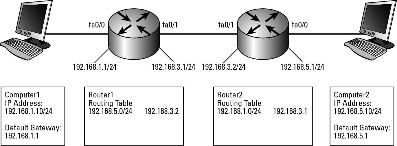
Now, I allow myself to create a small network for your amusement. This network has two routers and two workstations, with the workstations placed on the far ends of the network. Figure 4-1 illustrates this network. On it, the routers are configured so that the FastEthernet 0/0 (fa0/0) interfaces are for the computer side of the network and the FastEthernet 0/1 (fa0/1) interfaces are for the external side. Interface types are covered in Chapter 3 of this minibook.
Figure 4-1: A small routable network.

Initially, if you sit at Computer1 and attempt to contact Computer2, you cannot make the connection. If you use commands such as ping or traceroute (tracert on Windows) on Computer2 to troubleshoot the connection, you receive the following results:
C:>Ping 192.168.5.10
Pinging 192.168.5.10 with 32 bytes of data:
Reply from 192.168.1.1: Destination host unreachable.
Reply from 192.168.1.1: Destination host unreachable.
Reply from 192.168.1.1: Destination host unreachable.
Reply from 192.168.1.1: Destination host unreachable.
Getting network info from your router
If your network has only one router, what routing do you need to deal with? Other than enabling routing on the router, nothing needs to be done, because the router automatically adds routes in its routing table for all directly connected interfaces. So if you take a look at the interfaces on the router, you find a list of interfaces like the following:
Router1>enable
Password:
Router2#show ip interface brief
Interface IP-Address OK? Method Status Protocol
FastEthernet0/0 192.168.1.240 YES NVRAM up up
FastEthernet0/1 192.168.5.1 YES manual up up
Loopback0 192.168.255.254 YES manual up up
Now, if you look at the routing table (using the show ip route command) and specify that it show the connected interfaces, you see two routes that allow data to be transferred between these two interfaces. When data arrives on one interface, if it is destined for the other network segment, it is passed through the other interface.
Router1>enable
Password:
Router1#show ip route connected
C 192.168.3.0/24 is directly connected, FastEthernet0/1
C 192.168.1.0/24 is directly connected, FastEthernet0/0
In addition to the routing table, you can also get data about your routes from the show ip route summary command, which shows a list of networks or subnets for your connected interfaces.
Router1>enable
Password:
Router1#show ip route summary
IP routing table name is Default-IP-Routing-Table(0)
IP routing table maximum-paths is 16
Route Source Networks Subnets Overhead Memory (bytes)
connected 2 0 144 272
static 0 0 0 0
Total 2 0 144 272
Configuring the second router
To make your sample network a little more realistic, a second router gives you a total of three network segments. You are not putting any computers on the middle segment; you would encounter this typical configuration if you were to lease a private link or virtual circuit from your telephone company or if you were routing over an internal backbone connection on your network.
In this case, the networks you want to route between (containing Computer1 and Computer2) are not directly connected to a single router; rather, one segment is directly connected to each router on your network. Note that you would normally configure each computer to use the local router as the default gateway, so this is expected in this scenario. When you issue a command such as ping to test the connection to the remote computer whose IP address is 192.168.5.10, the computer performs the logical AND process on your IP address and the remote IP address using the subnet mask. In this case, the AND process identifies the destination address as a remote address. In all cases where the address is remote, the computer consults its local routing table. In this case, nothing is in the local routing table other than the default routes and the route to the default gateway. Because no routes are closer, the computer uses the “catch all” route through the default gateway.
When the ping command goes through, the results resemble the following. The error may be that the destination host is unavailable. Or it may be that the entire destination network is unavailable because the router at 192.168.1.1 does not know how to get to the destination network segment.
C:>ping 192.168.5.10
Pinging 192.168.5.10 with 32 bytes of data:
Reply from 192.168.1.1: Destination host unreachable.
Reply from 192.168.1.1: Destination host unreachable.
Reply from 192.168.1.1: Destination host unreachable.
Reply from 192.168.1.1: Destination host unreachable.
Ping statistics for 192.168.5.10:
Packets: Sent = 4, Received = 0, Lost = 4 (100% loss),
Approximate round trip times in milli-seconds:
Minimum = 0ms, Maximum = 1ms, Average = 0ms
The following code does two things. First, it enables routing on the router, which is necessary even to have routing on the two-segment network (this is not a default setting; you must instruct a router to route when there is more than one interface). Second, it adds a route to the 192.168.5.0 network segment (see Figure 4-2 for an illustration).
Router1>enable
Password:
Router1#configure terminal
Enter configuration commands, one per line. End with CNTL/Z.
Router1(config)#ip routing
Router1(config)#ip route 192.168.5.0 255.255.255.0 192.168.3.2
Router1(config)#exit
Figure 4-2: Adding routes to get to the destination network.

When you use the ping command, the remote computer at 192.168.5.10, you receive a slightly different error. The following error can have several causes. In general, Request timed out error means that the routers know how to get the data to its destination (otherwise you have the destination errors from the previous use of ping), or at least they think they do.
C:>ping 192.168.5.10
Pinging 192.168.5.10 with 32 bytes of data:
Request timed out.
Request timed out.
Request timed out.
Request timed out.
Ping statistics for 192.168.5.10:
Packets: Sent = 4, Received = 0, Lost = 4 (100% loss),
Approximate round trip times in milli-seconds:
Minimum = 0ms, Maximum = 1ms, Average = 0ms
If you have an issue with your routing tables, perhaps a router using the default gateway rather than the static route you should have configured, you might see the preceding error because the routers think they can route the data through to its destination. You may also see this error if the routes to the destination network are correct, but the routers on the reverse path are not correctly configured. The traceroute command may give you a little more information as to the nature of the error. In the following example, the Windows version of traceroute (tracert) is configured to trace the route for only four hops using the –h 4 option to modify the command.
D:utils>tracert –h 4 192.168.5.10
Tracing route to 192.168.3.1 over a maximum of 30 hops
1 <1 ms <1 ms <1 ms 192.168.1.1
2 * * * Request timed out.
3 * * * Request timed out.
4 * * * Request timed out.
Trace complete.
This code indicates only that your computer’s routing table is correct and that you passed the data on to your local router. Does your router know where to go from there? You still cannot be sure. You can connect to your router and verify the route, and then you can use ping to test the destination router and attempt to use traceroute to test the destination address, which shows you the router’s route to the destination:
Router1>enable
Password:
Router1#show ip route static
S 192.168.5.0/24 [1/0] via 192.168.3.2
Router1#ping 192.168.3.2
Type escape sequence to abort.
Sending 5, 100-byte ICMP Echos to 192.168.3.2, timeout is 2 seconds:
!!!!!
Success rate is 100 percent (5/5), round-trip min/avg/max = 1/1/4 ms
Router1#traceroute 192.168.5.10
Type escape sequence to abort.
Tracing the route to 192.168.5.10
1 192.168.3.2 0 msec 0 msec 4 msec
2 192.168.5.10 0 msec 4 msec 0 msec
If you are using these commands at the router, in my case Router1, you can receive replies, but you cannot get replies from Computer1, which is behind Router1. Because the commands work from Router1, you can be pretty sure that Router1 has the proper routes.
Think about the difference between the source addresses used for Computer1 and Router1. To Router2 and Computer2, the source address of Computer1 is 192.168.1.10, and Router1 is 192.168.3.1. So the source address is the difference, because Router2 knows how to get to 192.168.3.1, but does not know how to get to 192.168.1.10.
The net result is that you cannot communicate from Computer1 to Computer2, but what is the real reason? With the testing that was done, the route to the 192.168.5.0/24 network, so the problem is with the return trip. Effectively, if you were to use the ping command on Computer2 to test the address of Computer1, you would see the same thing you saw when this exercise started — the results would be either Destination net unreachable or Destination host unreachable. The solution is to get the correct route in place for that data to get back to Computer1 and ensure that IP routing is enabled giving you a network that looks like Figure 4-3. Because the last test completed successfully, you are sure that the ip routing command had already been run in Global Configuration mode, since if it was not enabled you would not have received any results.
Router2>enable
Password:
Router2#configure terminal
Enter configuration commands, one per line. End with CNTL/Z.
Router2(config)#ip routing
Router2(config)#ip route 192.168.1.0 255.255.255.0 192.168.3.1
Router2(config)#exit
Figure 4-3: Adding route to get back to source network.
Now to test the connection, go back to the original use of the ping command to test what was done at the very beginning. The result is now successful. You now have a valid route to and from the 192.168.5.0/24 network.
C: >ping 192.168.5.10
Pinging 192.168.5.10 with 32 bytes of data:
Reply from 192.168.5.10: bytes=32 time=1ms TTL=253
Reply from 192.168.5.10: bytes=32 time<1ms TTL=253
Reply from 192.168.5.10: bytes=32 time<1ms TTL=253
Reply from 192.168.5.10: bytes=32 time<1ms TTL=253
Ping statistics for 192.168.5.10:
Packets: Sent = 4, Received = 4, Lost = 0 (0% loss),
Approximate round trip times in milli-seconds:
Minimum = 0ms, Maximum = 1ms, Average = 0ms
When you examine the tracert again, success!
C:>tracert -h 4 192.168.5.10
Tracing route to 192.168.5.10 over a maximum of 4 hops
1 <1 ms 1 ms <1 ms 192.168.1.1
2 26 ms 17 ms 21 ms 192.168.3.2
3 9 ms 9 ms 14 ms 192.168.5.10
Trace complete.
The routing is now set up for a small network.
![]() As the network grows, it will be become more complex with more routes that need to be configured and maintained.
As the network grows, it will be become more complex with more routes that need to be configured and maintained.
Adding a third router
The only thing you might want to add to this network is a third router that gives your network’s users access to the Internet, as shown in Figure 4-4. To do so, you need to add additional routing entries on the new router, as well as configure the other routers to route Internet-destined traffic through Router3. The easy way to update your routes is to configure the gateway of last resort, which is used when you do not have a closer matching route. Configuring the gateway of last resort is equivalent to using the default gateway that you configure on your desktop computer. In fact, at the routing table level, these gateways are identical.
Figure 4-4: Default route out to Internet.

To apply this configuration change on Router1, you set the default route to point to 192.168.3.3 with the following command:
Router2>enable
Password:
Router1#configure terminal
Enter configuration commands, one per line. End with CNTL/Z.
Router1(config)#ip routing
Router1(config)#ip route 0.0.0.0 0.0.0.0 192.168.3.3
Router1(config)#exit
This command tells the system to pass all data, going to any IP address with any subnet mask, over to the router at 192.168.3.3 on the directly connected network of 192.168.3.0/24. The destination always needs to be a device on a directly connected network segment. When scanning the routing table for a route to a destination address, the route closest to the destination address is used. However, if no other entry is found in the routing table, this route will be used.
Running around and around with routing loops
As your network grows, so does the chance to introduce loops into the routing tables. Figure 4-5 shows this issue in action. Note that the route on Router2 to get to 192.168.1.0/24 is removed, and a route on Router3 to send traffic for 192.168.1.0/24 to Router2 is added incorrectly. The net effect is that if you sit at Computer2 and attempt to use the ping command to test the IP address of Computer1, the data bounces endlessly between Router2 and Router3.
Figure 4-5: A small routing loop.

![]() Well, endlessly is not quite correct. In Book I, Chapter 4, I discuss the structure of an IP packet and briefly introduced the Time to Live (TTL) in the packet header. This TTL is reduced by one every time a router processes an IP packet, and when the TTL is set to zero, it is removed from the network and an Internet Control Message Protocol (ICMP) message is sent to the source computer. Unlike the use of ICMP, when used with the
Well, endlessly is not quite correct. In Book I, Chapter 4, I discuss the structure of an IP packet and briefly introduced the Time to Live (TTL) in the packet header. This TTL is reduced by one every time a router processes an IP packet, and when the TTL is set to zero, it is removed from the network and an Internet Control Message Protocol (ICMP) message is sent to the source computer. Unlike the use of ICMP, when used with the ping command, ICMP sends status and control messages to IP hosts on the network. The message sent to the host is a Packet Expired in Transit message.
The following example shows a packet expiration message that was received when testing the connection to Computer1 from Computer2:
C:>ping 192.168.1.10
Pinging 192.168.1.10 with 32 bytes of data:
Reply from 192.168.3.3: TTL expired in transit.
Reply from 192.168.3.3: TTL expired in transit.
Reply from 192.168.3.3: TTL expired in transit.
Reply from 192.168.3.3: TTL expired in transit.
Ping statistics for 192.168.1.10:
Packets: Sent = 4, Received = 4, Lost = 0 (0% loss),
Approximate round trip times in milli-seconds:
Minimum = 0ms, Maximum = 0ms, Average = 0ms
To further illustrate this issue of expired packets, here is a copy of the output of the traceroute command for the same message. You let it go for only 10 hops by using the –h modifier, but this is enough to see the pattern that has developed as the data bounces between Router2 and Router3.
D:utils>tracert -h 10 192.168.1.10
Tracing route to 192.168.1.10 over a maximum of 10 hops
1 <1 ms <1 ms <1 ms 192.168.5.1
2 <1 ms <1 ms <1 ms 192.168.3.3
3 1 ms 1 ms 1 ms 192.168.3.2
4 1 ms 1 ms 1 ms 192.168.3.3
5 1 ms 1 ms 1 ms 192.168.3.2
6 2 ms 2 ms 2 ms 192.168.3.3
7 2 ms 2 ms 2 ms 192.168.3.2
8 3 ms 3 ms 3 ms 192.168.3.3
9 3 ms 3 ms 3 ms 192.168.3.2
10 4 ms 4 ms 4 ms 192.168.3.3
Trace complete.
This issue can be corrected by adjusting the route on Router3 to send data destined for the 192.168.1.0/24 network through Router1 rather than Router2. While this would get the data to the correct location, data for Computer1 would travel from Computer2 through both Router2 and Router3, and you should add a specific route on Router2 to directly route 192.168.1.0/24 data to Router1.
![]() Most routing loops give you an expired packet, so by using the
Most routing loops give you an expired packet, so by using the ping or traceroute commands, you can quickly identify the issue though output similar to what you see in this section. The lengthier task may be identifying the exact source of the problem, as it likely does with one routing table entry on one router. If you work sequentially through the routers on one end of the connection to the other end, you will find it.