
Chapter 3: Configuring Switches
In This Chapter
![]() Configuring a basic switch with the most common options
Configuring a basic switch with the most common options
![]() Configuring passwords for different interfaces
Configuring passwords for different interfaces
![]() Running the Setup Wizard
Running the Setup Wizard
![]() Setting up a new user
Setting up a new user
Switch configuration is important to maximizing the performance of your network. Although, in many cases, you can just take your new switch out of the box and plug it into a port on an existing switch and be fine, if you have not changed any of the settings on your other switches, you will not be getting the best performance from these switches or your network.
In this chapter, you find out how to apply a basic configuration on your switch and gain a firm grasp on what you need to do to complete your switch configuration, from examining ports to creating users to managing switches. I show you what you need to do from the command line as well as some of the graphical tools that are available to you with Cisco products. Later chapters in this minibook cover some of the more advanced switching topics.
Switching with the Internetwork Operating System (IOS)
The first step is to connect to your switch so you can make configuration changes. You will want to focus on different features, depending on whether you are working on a switch, router, or security device; however, the general IOS is the same regardless of what device you are managing (you may want to refer to Book I, Chapter 5, where I introduce IOS). Book I, Chapter 5 does not cover very many commands, but you follow the same process for entering the User EXEC mode, the Privileged EXEC mode, the Global Configuration mode, and for saving your configuration changes. This chapter will also show you Interface Configuration mode.
![]() To get help from the IOS, type a question mark at any point on the command line to see what commands are available or to find out how to complete a command that you are working on. Tab auto-completion of commands is also a default feature of the IOS, to use tab auto-completion just type enough of a command’s name to distinguish it from other commands, press the Tab key, and the command’s full name should appear automatically. Generally, by using these two features, you can quickly figure out most commands.
To get help from the IOS, type a question mark at any point on the command line to see what commands are available or to find out how to complete a command that you are working on. Tab auto-completion of commands is also a default feature of the IOS, to use tab auto-completion just type enough of a command’s name to distinguish it from other commands, press the Tab key, and the command’s full name should appear automatically. Generally, by using these two features, you can quickly figure out most commands.
![]() If you are entirely new to switch configuration, you can download a complete command reference guide for each IOS routing component; just go to Cisco’s website at
If you are entirely new to switch configuration, you can download a complete command reference guide for each IOS routing component; just go to Cisco’s website at www.cisco.com/cisco/web/psa/reference.html. On the page that appears, select your IOS version from the Products selection list. You may also find the LAN Switching guide for the current IOS version at the following link:
www.cisco.com/en/US/docs/ios/lanswitch/command/reference/lsw_book.html
Connecting to Your Switch
A few basic methods of making configuration changes to a switch are available, as shown here:
• Console connection: This method involves having direct physical access to the switch and making changes through your computer’s serial port and a rollover cable. This is command-line access to a switch and, typically, is the way you will configure an IP address on a new switch — because this method is a bit easier than trying to locate the new address that appears in DHCP or some other source.
• Telnet or SSH: These options give you remote command-line access to the switch to make configuration changes. There are a few requirements when using these features. The switch needs to be configured with an IP address, and the protocol that you want to use needs to be enabled.
• CiscoWorks: CiscoWorks LAN Management Solution (LMS) 4.0 is an enterprise workflow, monitoring, troubleshooting, reporting, and configuration management tool. With CiscoWorks, you have a true management tool for your entire network; but it comes with a price tag of approximately $10,000 with licenses to manage 300 network devices.
• Cisco Web Console: Represents the most popular, easy-to-use graphical user interface (GUI) that lets you configure your switches’ interfaces using a web browser, mouse, and keyboard, just like you navigate any website (see Figure 3-1).
Figure 3-1: Cisco’s Web Console is an easy-to-use GUI-based tool integrated into IOS.

Because you can always make a console connection to your switch, take a few minutes to locate a rollover cable for your switch as well as the console port on the switch. If you do not have a serial port on your computer, make plans to get a USB serial port adapter for your computer and test it with your Cisco devices. It is best to do this before you need to make an emergency connection to your switch.
If you have already enabled SSH access to your switch, ensure that you also disabled Telnet access. SSH is as easy to use as Telnet and the only secure remote access option to the command-line interface (CLI). If by chance you do not see a console port on your switch, check your documentation to see if you purchased a managed switch. An unmanaged switch does not support the advanced features covered in this minibook and does not allow configuration changes to be made to the switch; as such, it will not have a console port.
![]() In addition to the reliable command line, which is found on all Cisco devices, and the easier to use but sometimes less functional web-based interface that is found on some devices, Cisco has a variety of graphical management tools that you can use to manage configurations and to monitor network devices. At Cisco, you can find these tools, including (enterprise tool) CiscoWorks LAN Management Solution (LMS) and (small business tool) Cisco Configuration Professional, by going to
In addition to the reliable command line, which is found on all Cisco devices, and the easier to use but sometimes less functional web-based interface that is found on some devices, Cisco has a variety of graphical management tools that you can use to manage configurations and to monitor network devices. At Cisco, you can find these tools, including (enterprise tool) CiscoWorks LAN Management Solution (LMS) and (small business tool) Cisco Configuration Professional, by going to ww.cisco.com/en/US/products/sw/netmgtsw/index.html. Be sure to check them out — as either of them may make your life easier.
Revealing Basic Switch Configuration
You really do not need to do anything to your switch to get it working — just take it out of the box and connect it to your network. Unlike the router (covered in Book IV), all the ports on your switch are enabled by default, unless you disable them (see the “Configure” section, later in this chapter, for more on disabling switch ports). To get the most out of your switch, you need to do a bit of work, though none of it is too scary. The following sections discuss each of the major configuration items.
Setting a hostname
The hostname does not change how the switch functions, but when making remote connections to the switch, be sure that you are working on the correct device on the network. You do not want to think you are disabling an unused port on a remote switch, only to find out that you disabled the switch port to which the company president is connected, for example. Some people would call that a Career Limiting Move (CLM), and you do want to avoid those. To set the hostname, follow this example. Notice that exit is used to leave Global Configuration mode.
![]() This book uses code examples like the following one. In this example, you will see that some of the text is bold. The full example shows what is taking place in a console screen using the Cisco CLI, while the bold text shows what I typed.
This book uses code examples like the following one. In this example, you will see that some of the text is bold. The full example shows what is taking place in a console screen using the Cisco CLI, while the bold text shows what I typed.
Switch>enable
Password:
Switch#configure terminal
Enter configuration commands, one per line. End with CNTL/Z.
Switch(config)#hostname Switch1
Switch1(config)#exit
Examining ports and speeds
You will find several ports on your switch, including these:
• Stacking port: Used to connect switches together for common management and high-speed data transfer.
• Ethernet/FastEthernet/GigabitEthernet: Standard network interfaces used to connect different devices to your network. You see these along the front side of the switch, each numbered based on type, normally ranging from 8 to 50 ports.
• Console: Serial configuration port for command-line access to switch management and configuration.
• Power connector: This may accept a standard universal power cable — common on all computer equipment — supporting 110 to 220 volts or a 12V DC connector, as shown in Figure 3-2.
Figure 3-2: A typical 12V power connector for a switch.

Configuring interfaces
In previous chapters, I talk about switches and the series of ports you attach network devices to. When you enter the configuration of the Cisco IOS, these physical ports are logical interfaces, so you specify an interface by describing the physical location of a port. I will fully explain this while I walk you through the process.
![]() In this section, I examine the basics of configuring Ethernet, Fast Ethernet, and Gigabit Ethernet connections because they are typically the interfaces you see on your switch. There is not a substantial difference between copper or fiber connectors.
In this section, I examine the basics of configuring Ethernet, Fast Ethernet, and Gigabit Ethernet connections because they are typically the interfaces you see on your switch. There is not a substantial difference between copper or fiber connectors.
To configure the switch so that you can connect an appropriate device to a port and have it work, follow these steps:
1. Connect to your switch and get into Configuration mode using a set of commands like the following:
Switch1>enable
Password:
Switch1#configure terminal
Enter configuration commands, one per line. End with CNTL/Z.
2. Choose the interface by number.
You are able to choose from Ethernet, FastEthernet, or Gigabit Ethernet type interfaces.
3. Specify the interface number.
All ports in current IOS versions are numbered, starting at the motherboard in one of these formats: network-module-slot/port, 0/interface-card-slot/port, or network-module-slot/interface-card-slot/port. To specify an interface, you specify the location of the port that represents the interface. Effectively, all modules are connected to the motherboard slot on the switch, which is always slot 0 and the first zero in the interface name.
If you have a switch installed in a router HWIC or working with a chassis-based system, specify the slot that the card is installed into and then the interface in the format of 0/0/1 — 0 for the motherboard, 0 for the first HWIC slot, 1 for the first port on the network module.
In my case, the switch does not have an expansion module, so I specify 0 for the motherboard and 1 for the first port on the switch.
Switch1(config)#interface fastEthernet 0/1
![]() When working with switches, the first interface is numbered one, whereas when you work with most other Cisco devices, you find the first interface is zero.
When working with switches, the first interface is numbered one, whereas when you work with most other Cisco devices, you find the first interface is zero.
4. Set the specifics of the network connection or use the Auto settings for medium dependent interface crossover (MDIX), Duplex, and Speed settings.
MDIX modes include Auto or Off, Duplex modes include Full Duplex or Half Duplex, while speeds will typically be from 10 Mbps up to the speed of the interface. (I cover MDIX in Book III, Chapter 1.)
Switch1(config-if)#mdix auto
Switch1(config-if)#duplex auto
Switch1(config-if)#speed auto
5. Add a description to the interface.
Switch1(config-if)#description Firewall Connection
![]() It is a good idea, at least for important interfaces, to add a description. But because most ports will have computers belonging to ordinary network users, you may not want to add descriptions like “Bob’s office” for these ports. Important ports might include access points, routers, uplinks, or firewalls. Giving yourself a description may prevent you from changing the configuration on the wrong interface. These descriptions do not assist with the configuration; they just help prevent human error.
It is a good idea, at least for important interfaces, to add a description. But because most ports will have computers belonging to ordinary network users, you may not want to add descriptions like “Bob’s office” for these ports. Important ports might include access points, routers, uplinks, or firewalls. Giving yourself a description may prevent you from changing the configuration on the wrong interface. These descriptions do not assist with the configuration; they just help prevent human error.
![]() If you disable MDIX, be sure that you use the correct cable. If you have a computing device such as a computer, printer, or router, use a straight-through cable; if you want to connect two switches, you need a crossover cable. I discuss these cables in Book III, Chapter 1.
If you disable MDIX, be sure that you use the correct cable. If you have a computing device such as a computer, printer, or router, use a straight-through cable; if you want to connect two switches, you need a crossover cable. I discuss these cables in Book III, Chapter 1.
![]() If you are concerned about security in respect to how many computers a user connects, disable the MDIX setting so that the user will not be able to connect a personal switch or access point to their office network jack. Of course, the user could use a crossover cable if they are in the know, in which case public flogging of that user should be performed.
If you are concerned about security in respect to how many computers a user connects, disable the MDIX setting so that the user will not be able to connect a personal switch or access point to their office network jack. Of course, the user could use a crossover cable if they are in the know, in which case public flogging of that user should be performed.
Configuring the management interface
Before you can manage your switch, you need to configure a management interface. Unlike the routers in Book IV that allow for management on any configured interface, you are not able to associate IP addresses to the physical ports or interface; rather, you associate the IP address to a virtual interface that is implicitly created with a Virtual LAN (VLAN). Book III, Chapter 5, discusses VLANs, so in this section, I just cover the basics to get to the management interface of your switch. You need a switchport configured for the same VLAN as your management VLAN will be configured. If you want to manage your switch over the default VLAN, just follow these steps (notice end is used in this case to exit Global Configuration mode:
1. Create a new VLAN with the following command:
Switch1>enable
Switch1#configure terminal
Enter configuration commands, one per line. End with CNTL/Z.
Switch1#interface VLAN 1
Switch1(config-if)#ip address 192.168.1.241 255.255.255.0
Switch1(config-if)#end
![]() You do have the option of configuring your switch to use DHCP using the command
You do have the option of configuring your switch to use DHCP using the command ip address dhcp. This option can work well if you want to set reservations for the switch’s MAC address, but in most of the organizations that I deal with, all managed network devices are assigned static addresses for consistency and ensured connectivity. It would be a danger to network-management if I lost the ability to manage my network because a DHCP server went offline for too long.
If you were to exit the configuration now and check your running configuration, you would notice one configuration item a little strange:
Switch1>enable
Switch1#show running-config interface VLAN 1
Building configuration...
Current configuration : 82 bytes
!
interface Vlan1
ip address 192.168.1.241 255.255.255.0
no ip route-cache
end
This output clues you in that one important item is missing or, rather, that something is present that should not be. Unlike the reset of the switch ports, the VLAN interfaces are not enabled by default. You can have only one management interface or VLAN enabled at a time, so if you configure a second VLAN interface for management, the first one will be shut down or disabled. It will not be deleted, but it will be disabled. You will have to disable it and enable the other one.
2. Enter the following commands to start using the first VLAN interface again and shut down the second one:
Switch1>enable
Switch1#configure terminal
Enter configuration commands, one per line. End with CNTL/Z.
Switch1(config)#interface vlan 1
Switch1(config-if)#no shutdown
Switch1(config-if)#end
If you are working on the console or have terminal monitor running, you will receive a status message telling you that the interface has been enabled and can be used again. The message will be similar to the following:
00:00:52: %LINEPROTO-5-UPDOWN: Line protocol on Interface Vlan1, changed state to up
Now you have all the information required (and then some) to configure a switch interface. If you trust the default settings for the MDIX, Speed, and Duplex settings, you likely just need to assign an IP address and bring the management interface up. A description is nice to have and other configuration options are required based on configuration of other parts of your network, such as VLAN configuration.
Once you have the interface up and running, if you are using defaults for your MDIX, Speed, and Duplex settings, examine the interface to ensure that it has detected settings that you are happy with. Do this with the show interfaces command, as shown here. This switch does not support MDIX, but you should be able to locate the other settings.
Switch1>enable
Switch1#show interfaces fastEthernet 0/1
FastEthernet0/1 is up, line protocol is up (connected)
Hardware is Fast Ethernet, address is 0006.d6ab.a041 (bia 0006.d6ab.a041)
MTU 1500 bytes, BW 100000 Kbit, DLY 100 usec,
reliability 255/255, txload 1/255, rxload 1/255
Encapsulation ARPA, loopback not set
Keepalive set (10 sec)
Full-duplex, 100Mb/s, media type is 100BaseTX
input flow-control is unsupported output flow-control is unsupported
ARP type: ARPA, ARP Timeout 04:00:00
Last input 00:00:24, output 00:00:01, output hang never
Last clearing of “show interface” counters never
Input queue: 0/75/0/0 (size/max/drops/flushes); Total output drops: 0
Queueing strategy: fifo
Output queue: 0/40 (size/max)
5 minute input rate 0 bits/sec, 0 packets/sec
5 minute output rate 0 bits/sec, 0 packets/sec
2577 packets input, 213622 bytes, 2 no buffer
Received 2574 broadcasts (420 multicast)
0 runts, 0 giants, 0 throttles
0 input errors, 0 CRC, 0 frame, 0 overrun, 2 ignored
0 watchdog, 420 multicast, 0 pause input
0 input packets with dribble condition detected
2090 packets output, 157557 bytes, 0 underruns
0 output errors, 0 collisions, 2 interface resets
0 babbles, 0 late collision, 0 deferred
0 lost carrier, 0 no carrier, 0 PAUSE output
0 output buffer failures, 0 output buffers swapped out
![]() Pay attention to the values at the end of the previous command, because most of them will help you identify configuration issues.
Pay attention to the values at the end of the previous command, because most of them will help you identify configuration issues.
Within all this information, notice that the interface and line protocols should both be Up. In my case, the interface detected Full Duplex as well as a speed of 100 Mbps. When working with a switch, I will see only an IP address on the VLAN interface, which for Layer 2 switches will be the management interface, but will be considered a routing interface for Layer 3 switches. I can verify the IP address of the interface, and I can see if there are any packet errors on the interface. Incorrect Duplex settings between ends of a connection can cause packet errors.
![]() If you are working with a Layer 3 router, you have two types of configuration changes to work with: a full set of switch configuration commands in addition to a full set of routing commands. (Routing commands are covered in Book IV.)
If you are working with a Layer 3 router, you have two types of configuration changes to work with: a full set of switch configuration commands in addition to a full set of routing commands. (Routing commands are covered in Book IV.)
Setting the default gateway
The IP address on the management interface is already set, but that is not everything that you need to do. In most cases, as with the configuration of network devices, you need to configure at least a default gateway. In this case, the default gateway is not set in the interface, but for the entire switch.
To set the gateway of last resort, you enter Global Configuration mode and use the ip default-gateway command to set a route to a universal system. Remember, this needs to target a router that is directly connected to a network or segment to which your router is connected. The complete command looks like this:
Switch1>enable
Switch1#configure terminal
Enter configuration commands, one per line. End with CNTL/Z.
Switch1(config)#ip default-gateway 192.168.1.254
Switch1(config)#end
Setting passwords
Although it is not actually necessary to have a password on your switch, it is a very good idea to create one, especially if you configured the switch with an IP address on the management interface. If you do not configure a password but have enabled Telnet, anyone can connect to your switch from any interface and reconfigure your switch to their heart’s desire, giving themselves access to your entire internal network.
![]() The last several versions of the Cisco IOS for routers force you to set up passwords on your first boot, if you have not already enabled passwords.
The last several versions of the Cisco IOS for routers force you to set up passwords on your first boot, if you have not already enabled passwords.
Several types of passwords can be configured on your Cisco switch, such as Telnet and SSH connections, the console port, and the enable password. These password locations are good places to have password protection, but at the least, you should have an enable password because this acts as a master password on the switch and is required by any person who wants to enter Privileged EXEC mode.
![]() I have stopped being surprised when I visit a new client’s network and find that their network devices have no passwords or default factory passwords. It does, however, make my initial connections easier to accomplish. Always set or change system default passwords to prevent unauthorized changes to your network devices.
I have stopped being surprised when I visit a new client’s network and find that their network devices have no passwords or default factory passwords. It does, however, make my initial connections easier to accomplish. Always set or change system default passwords to prevent unauthorized changes to your network devices.
Setting the enable password
The enable password is used every time you move from User EXEC mode to Privileged EXEC mode. This condition gives you security on your switch because Privileged EXEC mode is where all the dangerous commands are, including Global Configuration mode. To set an enable password you would use the following command:
Switch1>enable
Switch1#configure terminal
Switch1(config)#enable password mypass
This command creates an enable password that is stored in the configuration file. To view this password, show your running configuration using the following command:
Switch1>enable
Password:
Switch1#show running-config | include enable password
enable password mypass
The problem with the enable password is that it is stored in plain text in the configuration file. Anyone with access to your configuration file can read your password without any trouble. Cisco’s solution to this problem was to create a new type of password called the secret password. When you configure both an enable and a secret password, the secret password is the password that will be used to change from User EXEC mode to Privileged EXEC mode, instead of the weaker enable password. The following code sets both passwords for your switch:
Switch1>enable
Switch1#configure terminal
Switch1(config)#enable password mypass
Switch1(config)#enable secret mysecret
To see this in your configuration, use the following command:
Switch1>enable
Password:
Switch1#show running-config | include enable
enable secret 5 $1$BSX4$FZp.ZFvYSAGUEDn8dvr140
enable password mypass
![]() Most encrypted passwords in your configuration file use a weak reversible encryption and will be identified by a 7 in the password line, whereas the secret password is encrypted with a one-way MD5 hash with a 5 denoted in the password line. You may also see a 0 that identifies it as an unencrypted password.
Most encrypted passwords in your configuration file use a weak reversible encryption and will be identified by a 7 in the password line, whereas the secret password is encrypted with a one-way MD5 hash with a 5 denoted in the password line. You may also see a 0 that identifies it as an unencrypted password.
Setting the Telnet password
If you need to remotely manage your switch, you will be able to choose between Telnet and SSH. Earlier in the chapter, I discussed the dangers of Telnet — that is, that it sends data over the network in plain text, which makes Telnet less secure when compared to SSH. Some people will make a justification for Telnet, and if they are running it only within a secured management network, then some of the risks are indeed mitigated.
In spite of risks, you should know how Telnet works and how to administer it, so I will show you how to do the setup. Telnet accesses the switch through the Virtual Terminal ports or vty ports. To see whether you are set up with vty ports on your switch, use the following command:
Switch1>enable
Password:
Switch1#show running-config | include line vty
line vty 0 4
The fourth line in the preceding code indicates that I have five vty ports on my switch, numbered from 0 to 4. This means that I can host up to five concurrent Telnet connections simultaneously on my switch. The chance of having five network administrators making connections to this switch at the same time is somewhat low. If you want to know how many connections your switch will support, use the following command to find out.
Switch1>enable
Password:
Switch1#configure terminal
Enter configuration commands, one per line. End with CNTL/Z.
Switch1(config)#line vty 0 ?
<1-181> Last Line number
<cr>
The preceding output tells you that the switch will support up to 182 total vty ports, but I can configure it to as low as 1 port by inserting a carriage return (pressing Enter).
To set the password for Telnet or vty port, use the following commands.
Switch1>enable
Password:
Switch1#configure terminal
Enter configuration commands, one per line. End with CNTL/Z.
Switch1(config)#line vty 0 4
Switch1(config-line)#password vtypass
Switch1(config-line)#exit
Switch1(config)#exit
Note the appearance of the Line Configuration mode prompt (config-line). This is the first time you have seen this in this book. Line Configuration mode configures different command line interfaces, such as the console and virtual terminal ports (vty).
To have access to the switch for Telnet, you need to specify both an enable password and the Telnet password in your configuration.
Setting the SSH password
To set up access to the switch for SSH, a few additional steps are needed. SSH access is not possible with only a password; you need to have a user account created on your switch. You will see how to create users in the section “Working with Users”, later in this chapter. For now, I will assume that you have a user named remote with a password named remote. (Note: Do not use this type of password policy on your production network!)
To set up SSH access, you need to change the default vty terminal or create a new one. In this case, I will create a new vty for SSH access using the following commands:
Switch1>enable
Password:
Switch1#configure terminal
Enter configuration commands, one per line. End with CNTL/Z.
Switch1(config)#ip domain-name edtetz.net
Switch1(config)#crypto key generate rsa
The name for the keys will be: Switch1.edtetz.net
Choose the size of the key modulus in the range of 360 to 2048 for your
General Purpose Keys. Choosing a key modulus greater than 512 may take
a few minutes.
How many bits in the modulus [512]: 1024
% Generating 1024 bit RSA keys ...[OK]
Switch1(config)#
*Mar 17 00:59:53.971: %SSH-5-ENABLED: SSH 1.99 has been enabled
Switch1(config)#line vty 5
Switch1(config-line)#login local
Switch1(config-line)#transport input ssh
Switch1(config-line)#exit
Switch1(config)#exit
The preceding commands have completed four key tasks:
• Created a set of Secure Sockets Layer (SSL) encryption keys and enabled SSH access with the crypto command.
• Created a vty terminal pool of one terminal to be used specifically with SSH.
• Enabled the incoming transport to SSH rather than Telnet or the other supported protocols using the transport command.
• Set the login option to use the local users database. This authenticates SSH users by checking their credentials against the users found in the local users database.
![]() The
The crypto key command needs to be issued only one time on the switch. Once the key is generated, it can be used by all services that require cryptography or encryption services.
At this point, you can use an SSH client program (like PuTTY) to connect to the command-line interface on this switch on TCP port 22. Because Telnet is still enabled on vty ports 0 through 4, I can use the following command to disable Telnet access, or actually all remote access through that set of vty ports. By disabling the four default vty ports, I have reduced remote management of this switch to one SSH user at a time and eliminated unencrypted Telnet management traffic on my network. Therefore, I can still manage my switch remotely, but I will be required to use SSH.
Switch1>enable
Password:
Switch1#configure terminal
Enter configuration commands, one per line. End with CNTL/Z.
Switch1(config)#line vty 0 4
Switch1(config-line)#transport input none
Switch1(config-line)#exit
Switch1(config)#exit
Setting the console port password
Anyone with access to the console port on your switch can connect to it and have at least User EXEC mode access. If they happen to know the enable or secret password, they can enter Privileged EXEC mode. To prevent this, you can add an additional password to the configuration that will require password access to the console port. Of course, the bigger security question in a situation like this is why does this strange person have physical access to your switch, but that is covered in Book VI, Chapter 4.
To place a password on the console port, you use a system that is very similar to that of the vty ports. To do so, use the following commands:
SSH client program like putty Switch1>enable
Switch1#configure terminal
Enter configuration commands, one per line. End with CNTL/Z.
Switch1(config)#line con 0
Switch1(config-line)#password conpass
Switch1(config-line)#login
Switch1(config-line)#exit
Switch1(config)#exit
These commands add an extra layer of security on connection to this port.
Knowing where passwords sleep
Now that you have looked at all the available passwords, take a look at the running configuration to see how they are stored.
Switch1>enable
Switch1#show running-config
Building configuration...
Current configuration : 921 bytes
!
version 12.3
!
(Output truncated for brevity)
!
enable secret 5 $1$exG2$cxsOWeiMWa7a8SMo5dw51/
enable password enablepass
!
(Output truncated for brevity)
!
line con 0
password conpass
login
line vty 0 4
password termpass
login
!
end
Switch1#
![]() Notice that the only password that is not stored in plain text is the enable secret password. All of the other passwords are clearly readable to anyone who has access to the configuration file or command and are thus not very secure. Your configuration file has an option to encrypt all passwords, and in Book VI, Chapter 4, you read more about using encrypted passwords as a security best practice.
Notice that the only password that is not stored in plain text is the enable secret password. All of the other passwords are clearly readable to anyone who has access to the configuration file or command and are thus not very secure. Your configuration file has an option to encrypt all passwords, and in Book VI, Chapter 4, you read more about using encrypted passwords as a security best practice.
Banners
A banner is a message presented to a user who is using the switch. The type of banner you configured for use determines when this message is shown. You can configure three main types of banners on your Cisco switch, as shown here:
• Message of the Day (MOTD): This type of logon message has been around for a long time on Unix and mainframe systems. The idea of the message is to display a temporary notice to users, such as issues with system availability. However, because the message displays when a user connects to the device prior to login, most network administrators are now using it to display legal notices regarding access to the switch, such as unauthorized access to this device is prohibited and violators will be prosecuted to the full extent of the law and other such cheery endearments.
• Login: This banner is displayed before login to the system, but after the MOTD banner is displayed. Typically, this banner is used to display a permanent message to the users.
• Exec: This banner displays after the login is complete when the connecting user enters User EXEC mode. Whereas all users who attempt to connect to the switch see the other banners, only users who successfully log on to the switch see this banner, which can be used to post reminders to your network administrators.
To configure each of these banners and set them up on your switch, follow these commands:
Switch1>enable
Switch1#configure terminal
Enter configuration commands, one per line. End with CNTL/Z.
Switch1(config)#banner motd #
Enter TEXT message. End with the character ‘#’.
This device is for authorized personnel only.
If you have not been provided with permission to
access this device - disconnect at once.
#
Switch1(config)#banner login #
Enter TEXT message. End with the character ‘#’.
*** Login Required. Unauthorized use is prohibited ***
#
Switch1(config)#banner exec #
Enter TEXT message. End with the character ‘#’.
*** Ensure that you update the system configuration ***
*** documentation after making system changes. ***
#
Switch1(config)#exit
Notice that each of the banner lines ends with a # symbol; this is a delimiter to identify the end of the message. You can specify any character you want, but the character you choose is the one you will use to end the banner message. Here is what these messages look like when you connect to the switch:
Switch1 Con0 is now available
Press RETURN to get started!
This device is for authorized personnel only.
If you have not been provided with permission to
access this device - disconnect at once.
*** Login Required. Unauthorized use is prohibited ***
User Access Verification
Password:
*** Ensure that you update the system configuration ***
*** documentation after making system changes. ***
Switch1>
Working with Users
I mention in the earlier “Setting the SSH password” section that with SSH, user accounts are required in order to log on. These accounts can be stored in a local database on the switch or on a central access server named Terminal Access Controller Access-Control System (TACACS), which is an industry-standard authentication server. Most small organizations and even some larger ones rely on the local database for user authentication, so I describe this user creation option in this minibook.
To use the local database for authentication, you need to do two things in this order:
1. Create at least one user account.
2. Configure your switch to use the local database rather than a password, which is done on an interface basis.
Creating a user in the account database
To create a user in the account database, use a command like the following to specify the username and password:
Switch1>enable
Password:
Switch1#configure terminal
Enter configuration commands, one per line. End with CNTL/Z.
Switch1(config)#username remoteuser password remotepass
Switch1(config)#username edt password edpass
Switch1(config)#exit
Removing a user
To remove a user, you can use the standard no command and then specify the username in the same way that the following command removes the user named remoteuser from the local database.
Switch1>enable
Password:
Switch1#configure terminal
Enter configuration commands, one per line. End with CNTL/Z.
Switch1(config)#no username remoteuser
Switch1(config)#exit
Enable user-level protection
Finally, you need to enable the login local setting on the interfaces you want to protect with this user-level protection, using a command similar to the following:
Switch1>enable
Password:
Switch1#configure terminal
Enter configuration commands, one per line. End with CNTL/Z.
Switch1(config)#line aux 0
Switch1(config-line)#login local
Switch1(config-line)#exit
Switch1(config)#exit
Running Setup Wizard
If you unpack your switch and plug it in, you will be running the generic factory configuration. This configuration is enough to allow you to use the switch on the default VLAN — vlan 1 — and will have all auto options enabled for each port. There will not be a management interface for Telnet or SSH; but once a management IP is configured, you can connect with Telnet and the web browser to make configuration changes. The complete configuration is shown here:
Switch1>enable
Switch1#show running-config
Building configuration...
Current configuration : 723 bytes
!
version 12.1
no service pad
service timestamps debug uptime
service timestamps log uptime
no service password-encryption
!
hostname Switch
!
!
ip subnet-zero
!
!
spanning-tree mode pvst
no spanning-tree optimize bpdu transmission
spanning-tree extend system-id
!
!
interface FastEthernet0/1
!
interface FastEthernet0/2
!
(Omitted for brevity)
!
interface FastEthernet0/11
!
interface FastEthernet0/12
!
interface Vlan1
no ip address
no ip route-cache
shutdown
!
ip http server
!
line con 0
line vty 5 15
!
!
end
When you first unpack a new switch or if you have erased the configuration, when the switch boots for the first time, it will automatically enter setup. If your switch does not, you have the option of running setup from Privileged EXEC mode. Here is the basic setup process; within just a few minutes, you can have the management interface on your switch up and running:
Switch>enable
Switch#setup
--- System Configuration Dialog ---
Continue with configuration dialog? [yes/no]: yes
At any point you may enter a question mark ‘?’ for help.
Use ctrl-c to abort configuration dialog at any prompt.
Default settings are in square brackets ‘[]’.
Basic management setup configures only enough connectivity
for management of the system, extended setup will ask you
to configure each interface on the system
Would you like to enter basic management setup? [yes/no]: yes
Configuring global parameters:
Enter host name [Switch]: Switch1
The enable secret is a password used to protect access to
privileged EXEC and configuration modes. This password, after
entered, becomes encrypted in the configuration.
Enter enable secret: secretpass
The enable password is used when you do not specify an
enable secret password, with some older software versions, and
some boot images.
Enter enable password: enablepass
% Please choose a password that is different from the enable secret
Enter enable password: enable
The virtual terminal password is used to protect
access to the switch over a network interface.
Enter virtual terminal password: termpass
Configure SNMP Network Management? [no]:
Current interface summary
Interface IP-Address OK? Method Status Protocol
Vlan1 unassigned YES unset administratively down down
FastEthernet0/1 unassigned YES unset up up
FastEthernet0/2 unassigned YES unset up up
FastEthernet0/3 unassigned YES unset up up
FastEthernet0/4 unassigned YES unset down down
FastEthernet0/5 unassigned YES unset down down
FastEthernet0/6 unassigned YES unset down down
FastEthernet0/7 unassigned YES unset down down
FastEthernet0/8 unassigned YES unset up up
FastEthernet0/9 unassigned YES unset up up
FastEthernet0/10 unassigned YES unset up up
FastEthernet0/11 unassigned YES unset up up
FastEthernet0/12 unassigned YES unset up up
Enter interface name used to connect to the
management network from the above interface summary: vlan1
Configuring interface Vlan1:
Configure IP on this interface? [no]: yes
IP address for this interface: 192.168.1.241
Subnet mask for this interface [255.255.255.0] :
Class C network is 192.168.1.0, 24 subnet bits; mask is /24
Would you like to enable as a cluster command switch? [yes/no]: no
The following configuration command script was created:
hostname Switch1
enable secret 5 $1$HXb6$RZPOXPyDvYuOWOhvYUP1d.
enable password enablepass
line vty 0 15
password termpass
no snmp-server
!
!
interface Vlan1
no shutdown
ip address 192.168.1.241 255.255.255.0
!
interface FastEthernet0/1
!
interface FastEthernet0/2
!
(Omitted for brevity)
!
interface FastEthernet0/11
!
interface FastEthernet0/12
!
end
[0] Go to the IOS command prompt without saving this config.
[1] Return back to the setup without saving this config.
[2] Save this configuration to nvram and exit.
Enter your selection: [2]
Building configuration...
[OK]
Use the enabled mode ‘configure’ command to modify this configuration.
Switch1#
00:09:12: %LINK-3-UPDOWN: Interface Vlan1, changed state to up
00:09:13: %LINEPROTO-5-UPDOWN: Line protocol on Interface Vlan1, changed state to up
(Omitted for brevity)
Switch1#
Notice how little information you need to enter to get basic management access to your switch over the network. This includes Telnet access to switch.
After the setup wizard is complete, enter Configuration mode to update your configuration to disable Telnet in favor of SSH (as a secure option) and configure your other network interfaces.
Working with Web Console
If you refer to the default factory configuration, you will see a line that reads ip http server. This line enables a web server on your switch that lets you use your web browser — such as Firefox, Internet Explorer, or Google Chrome — with Java support to configure and manage your switch. So, if you are uncertain about using the command line, Web Console gives you the ability to make all of your configuration changes through a friendly Web GUI. There is even a spot where you can pass through command-line items for changes that do not exist in the GUI.
To start this process, open your web browser and connect to http://<management address of switch>. You will need to know the enable or secret password to connect this interface (see the earlier “Setting passwords” section). When you are presented with the authentication dialog box, you can ignore the username field and fill in the password field, unless you have created user accounts on your switch, in which case provide credentials for a valid user.
Dashboard
The dashboard is the main page that opens when you log on to Web Console (refer to Figure 3-1 to see the dashboard). In addition to showing you a graphical image of the switch with its active ports, the console gives you a brief look at the health of your switch:
• The Switch Information section gives you all the information you need to get warranty information about your product.
• The Switch Health section lets you identify any major problems related to bandwidth, packet errors, or the system fans.
• The Port Utilization section identifies which port(s) are being over-utilized if you have a bandwidth issue.
In Book III, Chapter 2, you read about the Mode button on the front of your switch. Next to the image of the switch at the top of Web Console is a View menu that lets you change the display of the port colors to identify the ports as the Mode button would. Here are the three items that can be displayed in the View drop-down list:
• Status: Sets active ports to green.
• Speed: Sets the port color based on the connected port speed.
• Duplex: Sets the port color based on the Duplex settings of the port.
![]() If you mouse over any of the ports, this web page has a pop-up window that shows the same settings as the View menu in one convenient display (refer to Figure 3-1).
If you mouse over any of the ports, this web page has a pop-up window that shows the same settings as the View menu in one convenient display (refer to Figure 3-1).
Configure
The Configure navigation menu has four options, Smartports, Port Settings, Express Setup, and Restart/Reboot. This menu gives you access to the main settings that you will likely want to configure on your switch. I discuss these settings briefly in the following sections.
Smartports
Because port configuration requires a bit of knowledge, Cisco simplified the process by creating Smartports, which are preconfigured settings you can easily apply to your switchports. Figure 3-3 shows you what the Smartports configuration looks like through the web GUI. You select the type of port you want to apply and then select the ports to which you want to apply this configuration.
![]() Smartports are really just a series of macros (which you can modify) that Cisco has preconfigured on your switch. (I examine Smartport macros in detail in Book III, Chapter 8.) The mysterious engineers at Cisco determined that for most networks, these base configurations for ports make a lot of sense. It is a bit of an all-or-nothing in that you can use Smartports to do your configuration, or you can do all of the configuration by hand; however, if you do some by hand, your configuration may be overwritten or incompatible with other Smartport configurations. Table 3-1 summarizes the Smartport roles that you will find on your switch.
Smartports are really just a series of macros (which you can modify) that Cisco has preconfigured on your switch. (I examine Smartport macros in detail in Book III, Chapter 8.) The mysterious engineers at Cisco determined that for most networks, these base configurations for ports make a lot of sense. It is a bit of an all-or-nothing in that you can use Smartports to do your configuration, or you can do all of the configuration by hand; however, if you do some by hand, your configuration may be overwritten or incompatible with other Smartport configurations. Table 3-1 summarizes the Smartport roles that you will find on your switch.
Figure 3-3: Smartports make complex port configuration much easier.


The following code shows you the settings that are applied for each one of these types of ports in the order they are applied. Note that the configuration on the port even shows you which macro runs to apply the setting. Although you have not yet looked at all these settings, spend a few minutes reviewing the changes that are made to the ports in each of these configurations. Note that trunk ports are used for the router, access points, and switches. This topic comes into play in Book III, Chapter 5, which introduces VLANs and their relationship to trunk ports. Also note the prevalence of spanning tree in this configuration, which you see in Book III, Chapter 6.
interface FastEthernet0/4
switchport mode access
switchport port-security
switchport port-security aging time 2
switchport port-security violation restrict
switchport port-security aging type inactivity
mls qos cos override
macro description cisco-desktop
spanning-tree portfast
spanning-tree bpduguard enable
!
interface FastEthernet0/5
switchport mode trunk
switchport nonegotiate
mls qos trust cos
macro description cisco-switch
spanning-tree link-type point-to-point
!
interface FastEthernet0/6
switchport mode trunk
switchport nonegotiate
mls qos trust cos
macro description cisco-router
spanning-tree portfast trunk
spanning-tree bpduguard enable
!
interface FastEthernet0/7
switchport mode access
switchport voice vlan 1
switchport port-security
switchport port-security maximum 2
switchport port-security aging time 2
switchport port-security violation restrict
switchport port-security aging type inactivity
mls qos trust device cisco-phone
macro description cisco-phone
spanning-tree portfast
spanning-tree bpduguard enable
!
interface FastEthernet0/8
switchport mode trunk
switchport nonegotiate
mls qos trust cos
macro description cisco-wireless
spanning-tree bpduguard enable
!
The Smartports page also has a Recommended System Setup check box. By selecting this check box, the macro will modify the default configuration on your switch to ensure that the following settings are in place. (Note: Someone at Cisco decided that these changes are important to an operating network. Although this decision may be debatable, these settings will not hurt your networks.)
errdisable recovery cause link-flap
errdisable recovery interval 60
udld aggressive
spanning-tree mode rapid-pvst
spanning-tree loopguard default
macro global description cisco-global
Port Settings
The Port Settings page allows you to configure your port settings as shown in Figure 3-4. These settings include the Speed and Duplex settings. Port settings also give you an easy way to set a description on your ports. Descriptions help you avoid configuring incorrect ports and make you pay close attention when making changes. Finally, you have the option to enable or disable a port here, which is the same as issuing the shutdown or no shutdown command.
Figure 3-4: The Port Settings page to configure your physical settings.

Express Setup
The Express Setup settings are shown in Figure 3-5. They give you an easy way to configure the management interfaces for your switch. These interfaces include the management interface, VLAN, IP configuration, and password. Other settings include the switch name and methods of making remote connections, such as Telnet, SSH, or http.
Figure 3-5: Express Setup provides you with management configuration.

Restart and Reset
Finally, you finish the “Configure” section with the Restart and Reset page. This page allows you to restart the switch, which is needed from time to time, but more importantly, here you can reset the switch back to the factory configuration. Even though performing this action from the command line is not too difficult, Web Console is even easier.
Monitor
The monitor section gives you access to three main items: Trends, Port Status, and Port Statistics. Again, much of this data is available to you through the console.
Trends
The Trends page gives you three nice graphs that can show you some of the issues you may be experiencing. The main items that Cisco decided to graph are Bandwidth Utilization, Packet Errors, and Port Utilization for a specific port.
Port Status
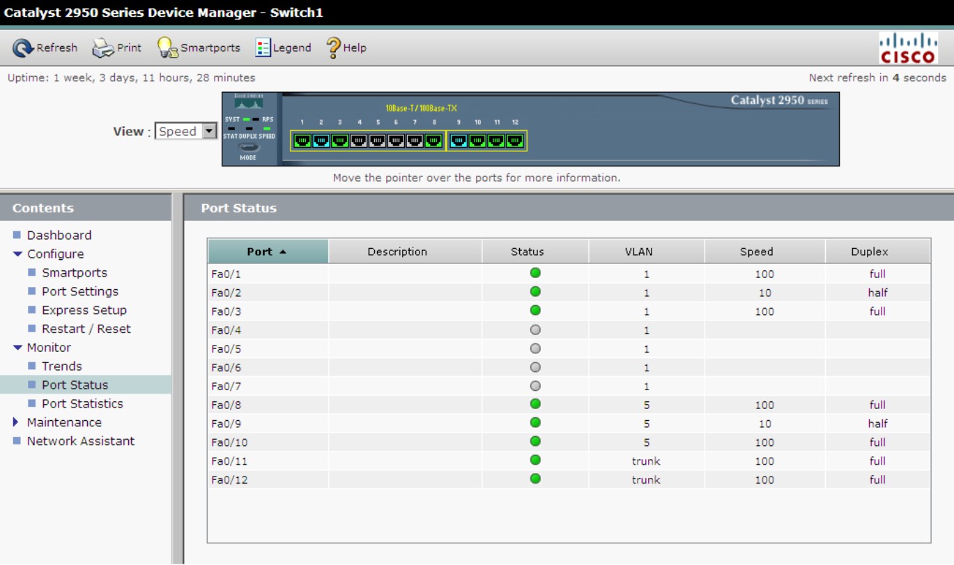
Whereas Port Settings allows you to set the configuration of a port, Port Status allows you to see how those settings are currently operating. When working with port settings that are in Auto mode, Port Status allows you to see how those ports negotiated their settings. As seen in Figure 3-6, the status includes the Description, current connection Status, VLAN, Speed, and Duplex.
Figure 3-6: Port Status displays current operating settings.
Port Statistics
Port Statistics can be valuable when attempting to troubleshoot switch issues. High numbers of errors over a period of time are indicators of a problem. From this page, you can clear the counters on a port and watch them go back up, expecting the error values on transmitted or received packets to be quite lower than the total transmitted or received.
Maintenance
There is only one item in the Maintenance menu, and it is for Telnet. This option gives you a single link that launches a Telnet session using your locally installed version of Telnet, if it is linked to your web browser, to open links with the telnet:// directive.
Network Assistant
Finally, the last link in Cisco’s Web Console is a promotion for Cisco’s Network Assistant, which is a graphical application that you can use to manage your network devices, such as routers, switches, and access points. The goal of this application is to make your network management tasks even easier by centralizing all of your management in one application. It even has an easy-to-click link that takes you to Cisco’s website to download a copy of the tool. You will need to create a Cisco ID to download this tool.