
Chapter 6: Adding Fault Tolerance with STP
In This Chapter
![]() Examining the basic role of STP on your network
Examining the basic role of STP on your network
![]() Setting up STP on your network
Setting up STP on your network
![]() Troubleshooting and debugging STP on your network
Troubleshooting and debugging STP on your network
A network segment is allowed to be only so long from end to end, because there is a required limit to how long it takes for the collision notification. If you create a network loop, which can happen accidentally, a problem will occur on the network as soon as a piece of data is sent on the network. The data is sent in a never-ending loop until the switch is crushed under the volume of data that it is attempting to forward to its destination, even though it is the same packet, again, and again, and again. If this data is broadcast data, it will span the entire network segment, regardless of how many switches make up the network.
Digital Equipment Corporation (DEC) created a protocol to deal with this problem and called it Spanning Tree Protocol or STP, and IEEE published it as a standard called 802.1D. This protocol has been improved multiple times over the years, mostly to deal with shortening the time it takes for the protocol to respond to changes on the network.
If you have or are planning to implement STP on your network, you will find the information in this chapter helpful because it explains the benefits of STP and possible issues involved in its normal course of operation.
Working with Spanning Tree Protocol (STP)
STP was developed before switches were created in order to deal with an issue that occurred with networks that were implementing network bridges. STP serves two purposes: First, it prevents problems caused by loops on a network. Second, when redundant loops are planned on a network, STP deals with remediation of network changes or failures.
![]() The difference between a bridge and a switch is that a switch functions like a multiport bridge; whereas a bridge might have two to four ports, a switch looks like a hub and, on an enterprise network, will usually have 12 to 48 ports. As you go through this chapter, note that STP technology uses the term bridges, when you are actually placing switches (multiport bridges). At the time STP was created, switches did not exist. Clear as mud?
The difference between a bridge and a switch is that a switch functions like a multiport bridge; whereas a bridge might have two to four ports, a switch looks like a hub and, on an enterprise network, will usually have 12 to 48 ports. As you go through this chapter, note that STP technology uses the term bridges, when you are actually placing switches (multiport bridges). At the time STP was created, switches did not exist. Clear as mud?
Building the initial topology
STP is a Layer 2 protocol that passes data back and forth to find out how the switches are organized on the network and then takes all the information it gathers and uses it to create a logical tree. Part of the information STP receives defines exactly how all the network switches are interconnected. STP builds this information by sending out network packets called Bridge Protocol Data Units (BPDUs or sometimes BDUs). These BPDUs — or rather the data in them — control the way STP determines the network topology.
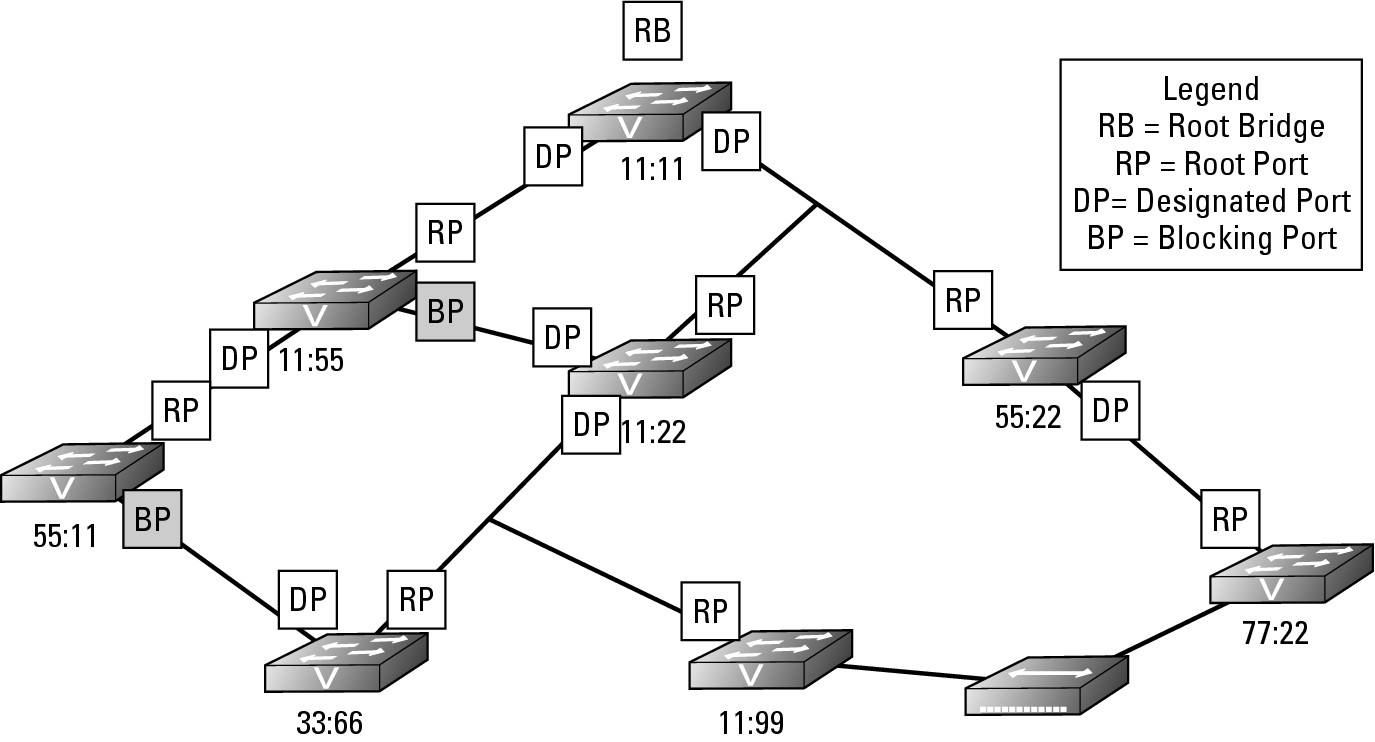
Figure 6-1 shows a basic network with simplified 4-digit MAC addresses for the switches. All the switches on the network will send BPDU frames to the entire network, even if a network that does not have any loops. These packets, by default, are sent out on the network every two seconds, are very small, and do not negatively affect the network traffic. If you are performing a packet capture on a network, however, be aware that these packets fill your capture screen quickly and can be distracting when reviewing your captured data. The initial process of sending BPDU frames will determine which switch will be the Root Bridge and act as the controller or manager for STP on the network. By default, the Root Bridge is the switch with the numerically lowest MAC address.
Figure 6-1: The Root Bridge on a small network.
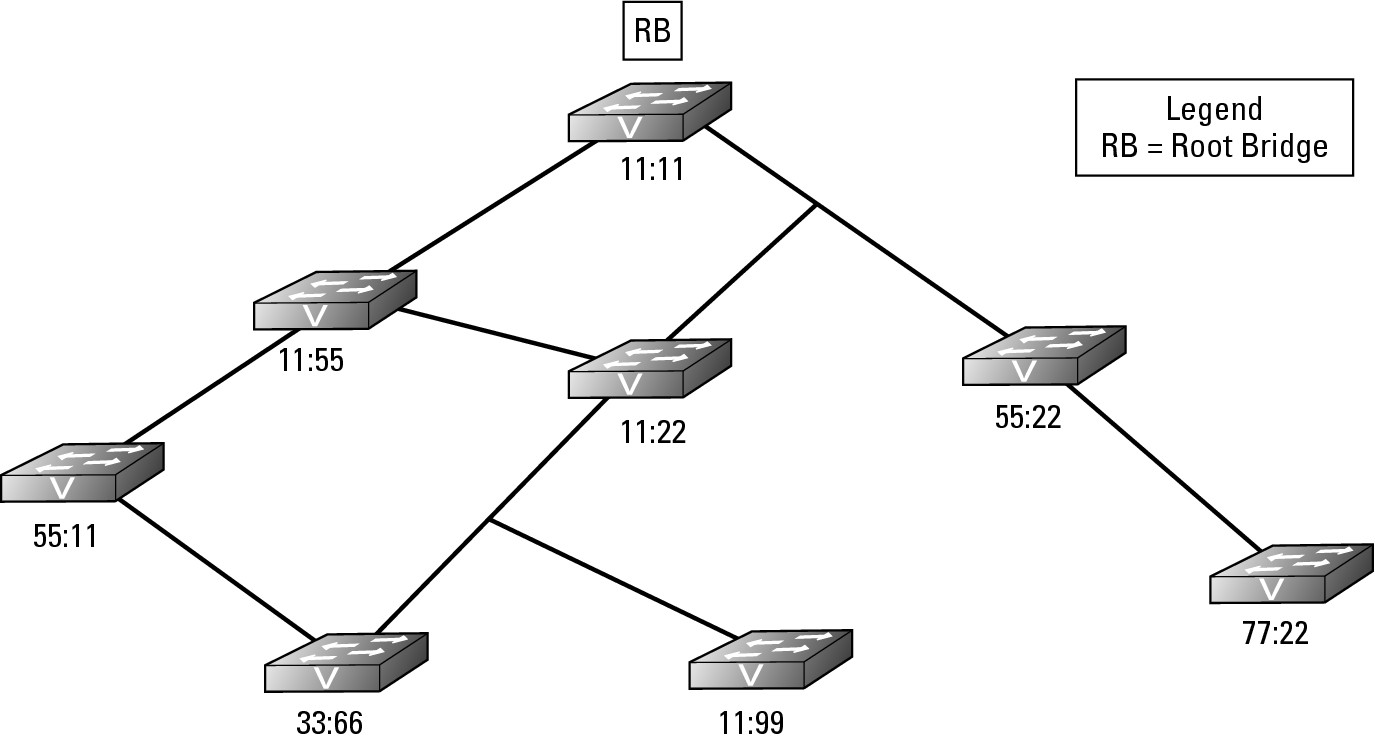
The BPDU, which every switch sends, contains information about the switch and its Bridge ID that uniquely identifies the switch on the network. The Bridge ID is made of two components: a configurable Bridge Priority value (which is 32,769 by default) and the switch MAC address. If none of the switches on your network has had its Bridge Priority values adjusted, then the switch with the lowest MAC address will be the Root Bridge; but if the Bridge Priority values on your network have been modified, the Root Bridge will be the switch with the lowest Bridge Priority value. The Root Bridge shown in Figure 6-1 is switch 11:11.
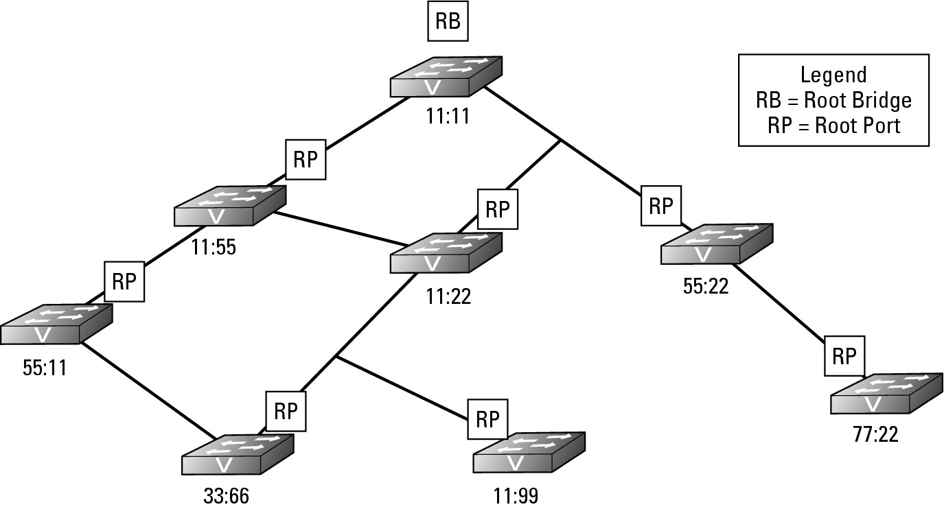
After the Root Bridge is identified, all other switches determine the quickest path from themselves to the Root Bridge. Some switches have more than one path to the Root Bridge due to a network loop. In Figure 6-1, switch 11:22 has two paths, one that is two hops away from the Root Bridge and one that is one hop away. If the speed of the networking technology is the same for all network segments, the path with the fewest number of hops is designated as the Root Port.
The switch will identify which of its interfaces is the Root Port. Each network technology has a rated speed, so based on the technology of each network segment between the switch and the Root Bridge, the switch is able to calculate the cost of each available path. Table 6-1 lists the STP cost associated with each network technology speed. Notice in the table that the data rate is inversely proportional to the STP cost.
In Figure 6-2, all the Root Ports are identified. In the event that a switch has two paths to the Root Bridge and each path has the same cost, then the switch will look at the BPDU frames from its closet neighbor on each of the paths. The switch will designate its Root Port based on the neighbor with the lowest Bridge ID.
Figure 6-2: The closest interface to the Root Bridge is the Root Port.
Identifying Designated Ports
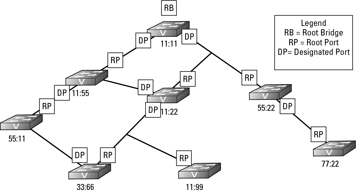
Each switch knows the least cost path to take to get to the Root Bridge, which may require passing data to another switch’s interface. For the sake of this example, I call the main switch that I am using in my example the reference switch and its neighbor the neighbor switch. The port on the next closest switch (neighbor switch) to the Root Bridge that is facing the reference switch is called the Designated Port. The reference switch will use the Designated Port as its path to get to the Root Bridge. Figure 6-3 identifies all the Designated Ports that the downstream switches will use to send data to the Root Bridge.
Figure 6-3:
The Designated Port represents the path that downstream switches will take.
Blocking loops
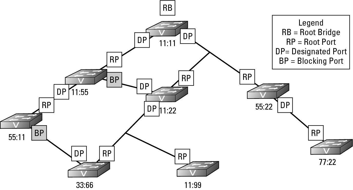
You still have one outstanding problem to resolve. There are still loops on this network that threaten to bring the current network down; however, by working through how all the Root Ports and Designated Ports are assigned, you have actually completed the work to resolve the loop issue on the network. In Figure 6-3, only two ports are used to connect to neighboring switches that are neither Root Ports nor Designated Ports. Because these ports do not have either role assigned to them, they are part of a loop on the network. If you review Figure 6-3, you should be able to identify the loops on the network. To resolve the loop issue, STP puts these ports without a role into Blocking state, which means these are Blocking Ports. Blocking Ports are ports that do not allow traffic to be sent or received through the port; it is blocking the traffic. Essentially, you could say that the Blocking Ports have been disabled, but they are not disabled. Since the ports are not disabled, the switch on the other end of the link still sees the link as active, but frames that are sent over that link (excluding BPDU frames) are dropped (blocked). Figure 6-4 shows you the completed STP diagram, including the Blocking Ports.
Figure 6-4: Selection of Blocking Port is based on the port having no other role.
Dealing with network changes
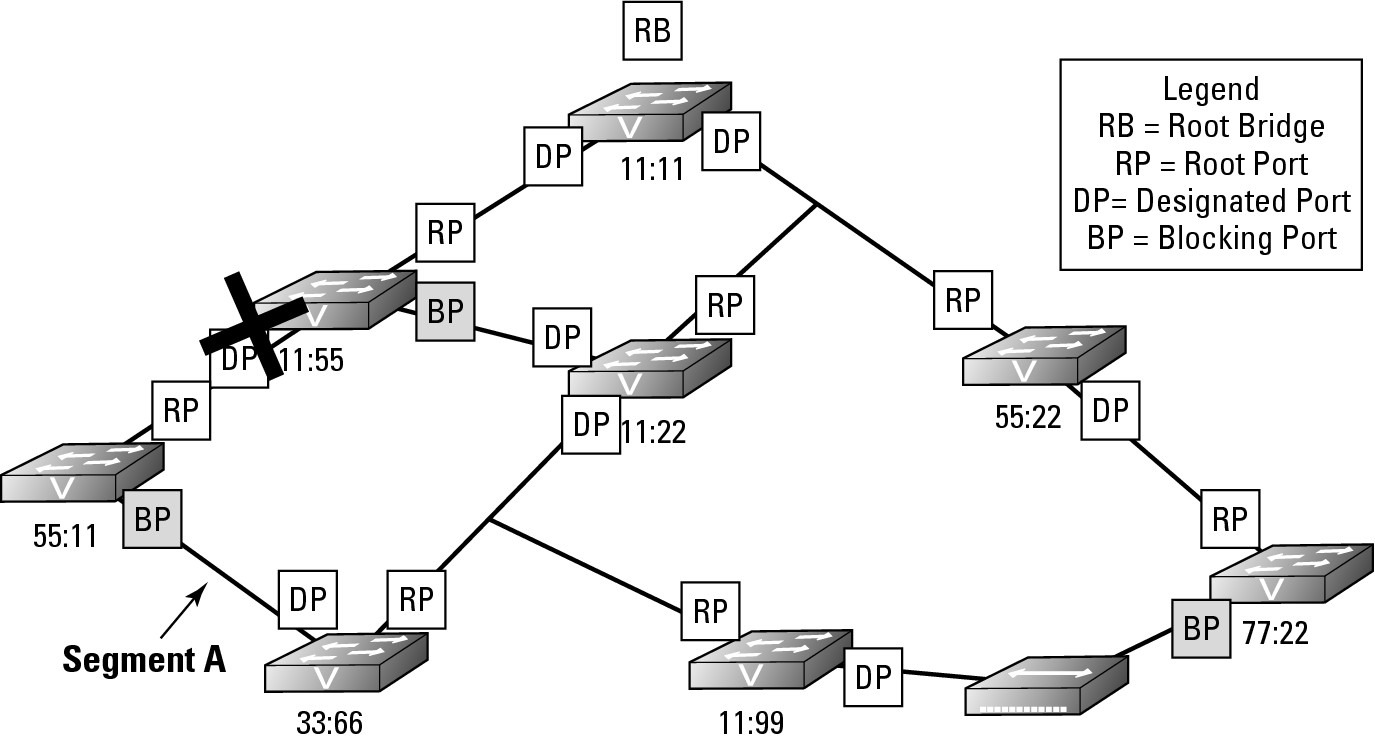
What happens when you connect a new hub or switch to this sample network? I will use a hub for this example because it lacks any network intelligence. In Figure 6-5, I connected a hub to a port on both switch 11:99 and switch 77:22.
Figure 6-5:
The introduction of a new device on the network causes a series of (hopefully, not unfortunate) events.
The net effect is actually the same as directly connecting these two switches with a standard network cable; I have created a loop on the network through switches 11:99, 11:22, 55:22, and 77:22. The hub operates at Layer 1 and does not know anything about Layer 2 or STP, so the hub treats the links of both of the ports, which were just connected as active and will happily pass data back and forth through this connection. The switches, on the other hand, do not treat this connection as active. Anytime an interface or port has its state changed to Up because either you connect a device or issue a no shutdown command on the interface, a switch follows a strict process, placing the port into one of the four STP port states shown in Table 6-2.
Here is what happens when a port’s state changes to Up:
1. Each switch to which the hub has been connected (switches 11:99 and 77:22) notices that the link state of one of their ports has changed to Up. Each switch puts the newly linked port in Listening state, which means that it sees and forwards BPDU frames, but does not pass other traffic. At this time, each switch does not know if this new link will create a loop on the network.
2. After a delay of 30 seconds, if the newly linked port does not see any BPDUs, or if the result of those BPDUs does not indicate a loop, the port goes into Learning state for 15 seconds and then transitions to Forwarding state. In this case, each switch 11:99 will have sent BPDUs on the port to which the hub is connected and switch 77:22 will have seen the BPDU frames, and vice-versa. Because of seeing each other’s BPDUs, these switches will know that they are connected to each other and are creating a loop. With this knowledge, they will start the process of calculating the path cost to the root bridge, which in this is a case of equal cost paths to Root Bridge; the path from each switch, through the hub will pass through two other switches. Because there are equal path costs, the tie is solved by designating the lowest priority switch as a Designated Port and blocking on the other port, as shown in Figure 6-6. With the assignment of a new Root Port, Designated Port, or identification a new Root Bridge, a change has been made to the STP structure on the network. Any change to the STP structure on the network is called a topology change, and the layout of the STP structure is called the STP topology.
Figure 6-6: The new device will cause a loop, so one switch sets its port in a Blocking state.

In Figure 6-7, I created an interface problem in switch 11:55. I either typed the shutdown command in the interface or unplugged the cable; either way, the state of the port has changed to Down. Suddenly, the other devices connected to switch 55:11 do not have a path to the rest of the network as they were using that inter-switch connection and the other inter-switch connection is in a Blocking state. The following process occurs:
1. Switch 55:11 detects a change on an interface or notices that the BPDU data stops showing up, so the switch will flood the change in its BPDU frames and send them out through all switch ports, including the Blocking Port that it knew had a connection to the rest of the network at one time.
2. In the review of the topology, switch 55:11 actually announces via its BPDU frame that a topology change has occurred by sending a Topology Change Notification (TCN) BPDU. This data goes directly to the Root Bridge, which sends BPDU updates to the rest of the network. Because of this topology change, a few things happen:
a. Switch 55:11 takes the port on Segment A (see Figure 6-7) and places it in Forwarding state, after identifying this action as the way to correct the isolation it is undergoing.
b. The Root Bridge receives notification of the change.
c. Other switches on the network receive notification of the change.
Figure 6-7: Responding to network failures.
This activation process happens quickly after a failure is noticed, but detecting the failure can take several seconds. The delay in detecting a failure is because the switch should not have received several of the expected BPDU frames over the link before transitioning the relevant ports from Blocking to Forwarding. Even with this small delay, which may create a problem for some of your network-based applications, the corrective action taken by STP is much faster than your locating the interface at issue and establishing the links manually.
Setting Up STP
All switches from Cisco ship with STP enabled by default, but if STP is misconfigured for any reason, you can easily enable it. To enable spanning tree, connect to your switch and type spanning-tree mode <selected mode> while in Global Configuration mode. Table 6-3 lists some of the differences among the different versions of spanning tree. The current version of the IOS supports the following modes and defaults to PVST mode.
Switch2> enable
Switch2# configure terminal
Switch2(config)#spanning-tree mode ?
mst Multiple spanning tree mode
pvst Per-Vlan spanning tree mode
rapid-pvst Per-Vlan rapid spanning tree mode
After you enable a version of STP on your switch, you need to configure some of the options for the STP, with the biggest option being one of the fast technologies. One the most popular of these options is PortFast, which I cover in the upcoming “STP and PortFast” section.
Switch2> enable
Switch2# configure terminal
Switch2(config)#spanning-tree ?
backbonefast Enable BackboneFast Feature
etherchannel Spanning tree etherchannel specific configuration
extend Spanning Tree 802.1t extensions
loopguard Spanning tree loopguard options
mode Spanning tree operating mode
mst Multiple spanning tree configuration
pathcost Spanning tree pathcost options
portfast Spanning tree portfast options
uplinkfast Enable UplinkFast Feature
vlan VLAN Switch Spanning Tree
STP and issues with VLANs
Before talking about PortFast, I want to discuss the issue that you encounter when implementing VLANs on a network that is supporting STP. When STP was developed, the concept of a VLAN had not even entered anyone’s thoughts. When VLANs started to become popular, the issue with mixing these two technologies on the same network became apparent; STP only expects to support one network.
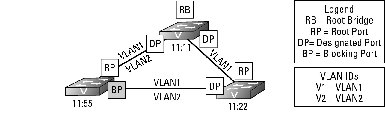
Examine Figure 6-8 for a moment. If you had to live with the original version of STP, the port that will be blocked is identified on switch 11:55. In this implementation, VLAN1 is configured to run on all network segments, but VLAN2 is implemented on only two of the three network segments. However, now spanning tree has blocked access to the two portions of VLAN2. The upshot is that computers on these segments, if they are part of VLAN2, will not be able to communicate. To resolve this problem, Per VLAN Spanning Tree (PVST) implements an instance of STP for each VLAN. With PVST, the STP topology for VLAN1 will remain the same; but because VLAN2 is implanted on two segments, it will not form a loop because there is a break in the network between switches 11:11 and 11:22. In the case of the STP topology for VLAN2, there would be no Blocking Ports.
Figure 6-8:
VLAN and STP interaction.
When providing VLAN support for STP you encounter two protocols on your Cisco switches:
• MSTP: An open standards version of STP that allows you to initiate multiple copies of STP on your switch and manually configure separate zones or implementations. MSTP uses the same basic frame structure as RSTP but after the RSTP data in the frame concludes, MSTP adds an additional section to support VLANs on your network. This structure makes it backwards compatible with RSTP, which may be running on your network.
• PVST: Per VLAN Spanning Tree is more popular than MSTP, especially if a very structured VLAN solution is implemented on your network. Per VLAN creates an instance of STP for each VLAN running on your network, up to a limit of 64 VLANs. If you need to implement more than 64 VLANs on your network, only 64 VLANs can have an instance of STP operating.
STP and PortFast
Another problem that you may encounter with spanning tree relates to the time it takes to transition ports over to the Forwarding state. This factor of time is not an issue for many people, but it can cause problems for some. If I power up my computer in the morning, power goes to the network card immediately (earlier, if I have Wake-on-LAN for my NIC), and the port on the switch enters the Listening state. By the time the OS wants to start up the network card drivers and get an address from DHCP, the port on the switch is in Forwarding state, which works well most of the time. If, however, I unplugged the NIC on my laptop to move it to another desk, Windows will tell me that it has a problem communicating on the network. Why? The NIC connected to the port changed the link state of the port to Up, Windows immediately tried to get a DHCP address, but the port is not yet in a Forwarding state. This is a common problem when using STP on your network. In a few more seconds, Windows will attempt to get an IP address again, and it will succeed.
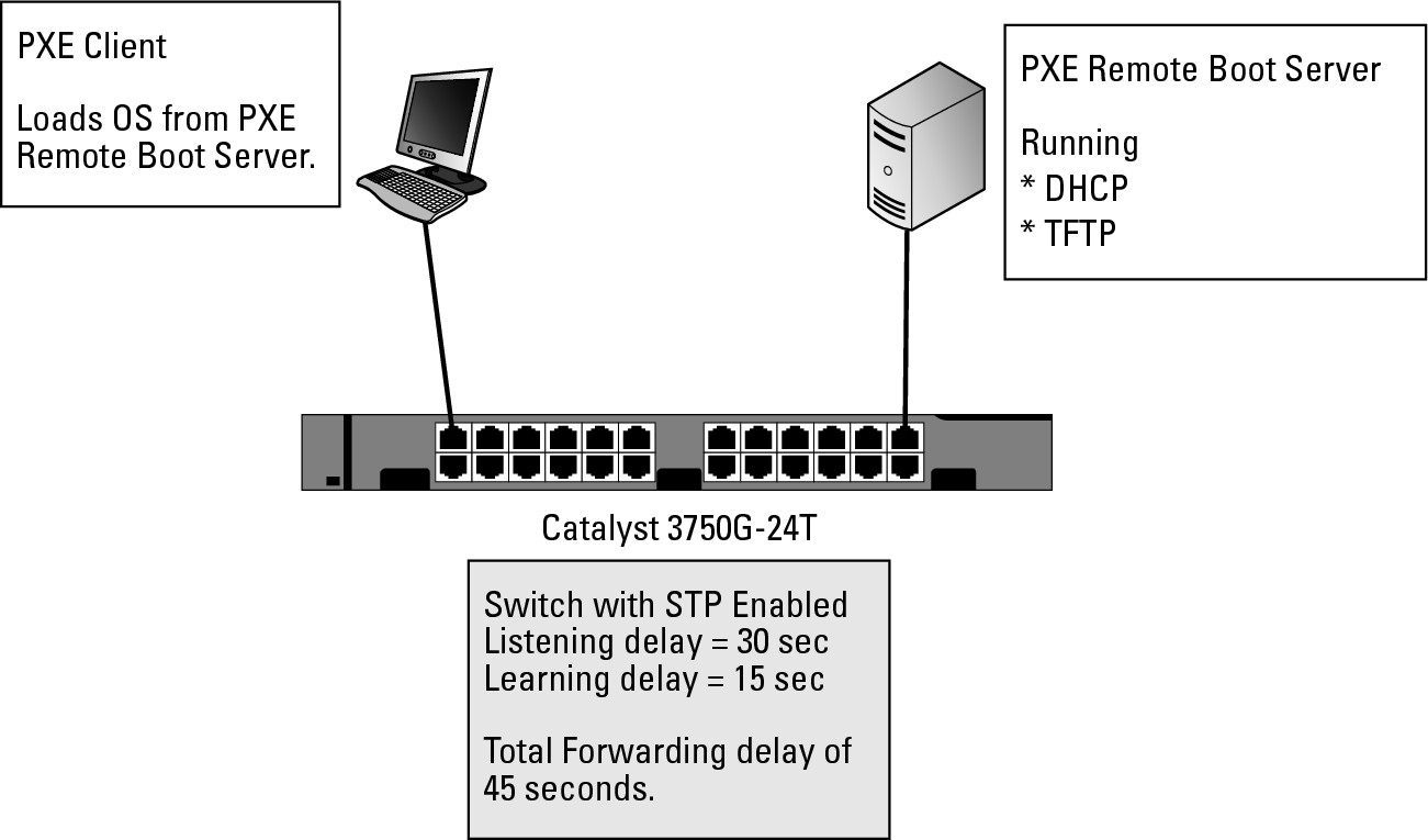
The other time you may see this issue is with Pre-Boot Execution (PXE) devices, such as Windows Deployment Services. Figure 6-9 shows a typical PXE implementation. Here is what happens with PXE: You apply power to your computer, which activates the NIC, but less than five seconds later, the computer’s POST finishes and the NIC attempts to get an IP address from DHCP so that it can load a boot image directly from the PXE server, which fails. The computer attempts to get an IP address from a DHCP server several times within approximately 10 seconds, after which it gives up and moves onto another boot device, such as the hard drive. The unfortunate part of this process is that because it fails to get an IP address or connect with the PXE server, you are not able to install your new operating system image on that computer. The problem with this scenario is that because STP makes the computer wait 45 seconds prior to forwarding traffic on the port, the PXE network boot has timed out.
Figure 6-9: PortFast can resolve networking problems, but can cause other problems.
PortFast is the solution to this problem of delays when client computers are connecting to switches. PortFast is not enabled by default. With PortFast enabled on a port, you effectively take the port and tell spanning tree not to implement STP on that port. This solution is not a bad one if only one computer is plugged into the port — so that people will not be creating accidental loops on the network, which can be frighteningly easy to do. I once had a whole network sporadically brought down for the better part of a week, thanks to a Windows Tablet PC that was set to bridge the wireless connection and the wired connection. Both of these networks were implemented on the same VLAN. When the user left the wireless card enabled and plugged into the wired network, a loop was created, bringing down the network. In this case, STP was enabled, but PortFast was also enabled on the end-user ports so the STP port evaluation process was not conducted.
Setting PortFast on all ports
While there may be some ports you want to exclude from the PortFast configuration (you will see how to handle them in the next sub-section), if you want most ports to use PortFast you make that default setting. To set PortFast on all ports from Global Configuration mode, use the command spanning-tree portfast default:
Switch2> enable
Switch2# configure terminal
Switch2(config)#spanning-tree portfast ?
bpdufilter Enable portfast bdpu filter on this switch
bpduguard Enable portfast bpdu guard on this switch
default Enable portfast by default on all access ports
Setting PortFast on specific ports
You can also implement PortFast on specific ports, as illustrated here, where the following command enables PortFast for FastEthernet ports 1 through 10. Notice the big warning about the dangers of PortFast.
Switch2#configure terminal
Enter configuration commands, one per line. End with CNTL/Z.
Switch2(config)#interface range
Switch2(config)#interface range fastEthernet 0/1 -10
Switch2(config-if-range)#spanning-tree portfast
%Warning: portfast should only be enabled on ports connected to a single
host. Connecting hubs, concentrators, switches, bridges, etc... to this
interface when portfast is enabled, can cause temporary bridging loops.
Use with CAUTION
%Portfast will be configured in 10 interfaces due to the range command
but will only have effect when the interfaces are in a non-trunking mode.
Switch2(config-if-range)#end
The BPDU Guard option removes the danger expressed in the warning. In this case, I incorrectly selected my ports, and ports 1 and 2 should have spanning tree enabled normally on them. BPDU Guard throws up warnings right away to prevent the loop that has been created from causing a problem on my network. When a PortFast port with BPDU Guard on it sees a BPDU frame, the action causes the switch to say, “Hey, this port is configured incorrectly!” and immediately the switch puts that port in an error state.
Switch2#configure terminal
Enter configuration commands, one per line. End with CNTL/Z.
Switch2(config)#interface range fastEthernet 0/1 -10
Switch2(config-if-range)#spanning-tree bpduguard enable
Switch2(config-if-range)#
3d14h: %SPANTREE-2-BLOCK_BPDUGUARD: Received BPDU on port FastEthernet0/2 with BPDU Guard enabled. Disabling port.
3d14h: %PM-4-ERR_DISABLE: bpduguard error detected on Fa0/2, putting Fa0/2 in err-disable state
3d14h: %SPANTREE-2-BLOCK_BPDUGUARD: Received BPDU on port FastEthernet0/1 with BPDU Guard enabled. Disabling port.
3d14h: %PM-4-ERR_DISABLE: bpduguard error detected on Fa0/1, putting Fa0/1 in err-disable state
3d14h: %LINEPROTO-5-UPDOWN: Line protocol on Interface FastEthernet0/2, changed state to down
3d14h: %LINEPROTO-5-UPDOWN: Line protocol on Interface FastEthernet0/1, changed state to down
3d14h: %LINK-3-UPDOWN: Interface FastEthernet0/2, changed state to down
3d14h: %LINK-3-UPDOWN: Interface FastEthernet0/1, changed state to down
Switch2(config-if-range)#end
To correct the error state on the port, connect to that port in Interface Configuration mode and then shut down and re-enable those ports as shown here:
Switch2#configure terminal
Enter configuration commands, one per line. End with CNTL/Z.
Switch2(config)#interface range
Switch2(config)#interface range fastEthernet 0/1 -10
Switch2(config-if-range)#shutdown
Switch2(config-if-range)#no shutdown
Troubleshooting STP
The first part of troubleshooting STP is to gather additional information about the running protocol. Our good buddy show will get you started. If you have read other chapters on protocols, you will know that the show command has a great deal of information to display, and STP is no different.
Here is a list of the show options available to STP on Cisco switches:
Switch2> enable
Switch2#show spanning-tree ?
active Report on active interfaces only
backbonefast Show spanning tree backbonefast status
blockedports Show blocked ports
bridge Status and configuration of this bridge
detail Detailed information
inconsistentports Show inconsistent ports
interface Spanning Tree interface status and configuration
mst Multiple spanning trees
pathcost Show Spanning pathcost options
root Status and configuration of the root bridge
summary Summary of port states
uplinkfast Show spanning tree uplinkfast status
vlan VLAN Switch Spanning Trees
| Output modifiers
<cr>
Because PVST is the default STP version, it also includes statistical information about the VLANs for which STP is running.
Switch2> enable
Switch2#show spanning-tree summary
Switch is in pvst mode
Root bridge for: none
EtherChannel misconfig guard is enabled
Extended system ID is enabled
Portfast Default is disabled
PortFast BPDU Guard Default is disabled
Portfast BPDU Filter Default is disabled
Loopguard Default is disabled
UplinkFast is disabled
BackboneFast is disabled
Pathcost method used is short
Name Blocking Listening Learning Forwarding STP Active
---------------------- -------- --------- -------- ---------- ----------
VLAN0001 1 0 0 2 3
VLAN0002 1 0 0 1 2
VLAN0005 1 0 0 1 2
VLAN0010 1 0 0 1 2
VLAN0015 1 0 0 1 2
VLAN0020 1 0 0 1 2
---------------------- -------- --------- -------- ---------- ----------
6 vlans 6 0 0 7 13
Switch2> enable
Switch2#show spanning-tree root
Root Hello Max Fwd
Vlan Root ID Cost Time Age Dly Root Port
---------------- -------------------- ------ ----- --- --- ----------------
VLAN0001 32769 0006.d6ab.a040 19 2 20 15 Fa0/2
VLAN0002 32770 0006.d6ab.a040 19 2 20 15 Fa0/2
VLAN0005 32773 0006.d6ab.a040 19 2 20 15 Fa0/2
VLAN0010 32778 0006.d6ab.a040 19 2 20 15 Fa0/2
VLAN0015 32783 0006.d6ab.a040 19 2 20 15 Fa0/2
VLAN0020 32788 0006.d6ab.a040 19 2 20 15 Fa0/2
This output shows much more information. To abridge the output, I show only the STP information for VLAN1. Here are some of the major pieces of information in this output:
• Bridge address: The MAC address of the current switch
• Address of the Root Bridge: The MAC address of the current Root Bridge
• Delays and forwarding times: The current configured values of the forwarding and delay timers
• Port status for that VLAN: Status of the ports configured in the displayed VLAN
In the following output of show spanning-tree from Switch1, note that all listed ports are in a Forwarding (FWD) state. Currently, port 11 and port 12 are connected to Switch2, creating a loop.
Switch1>enable
Switch1#show spanning-tree
VLAN0001
Spanning tree enabled protocol ieee
Root ID Priority 32769
Address 0006.d6ab.a040
This bridge is the root
Hello Time 2 sec Max Age 20 sec Forward Delay 15 sec
Bridge ID Priority 32769 (priority 32768 sys-id-ext 1)
Address 0006.d6ab.a040
Hello Time 2 sec Max Age 20 sec Forward Delay 15 sec
Aging Time 300
Interface Role Sts Cost Prio.Nbr Type
---------------- ---- --- --------- -------- --------------------------------
Fa0/1 Desg FWD 19 128.1 P2p
Fa0/2 Desg FWD 100 128.2 Shr
Fa0/3 Desg FWD 19 128.3 P2p
Fa0/11 Desg FWD 19 128.11 P2p
Fa0/12 Desg FWD 19 128.12 P2p
In the following output, you see what the ports look like on Switch2.
Switch2>enable
Switch2#show spanning-tree
VLAN0001
Spanning tree enabled protocol ieee
Root ID Priority 32769
Address 0006.d6ab.a040
Cost 19
Port 11 (FastEthernet0/11)
Hello Time 2 sec Max Age 20 sec Forward Delay 15 sec
Bridge ID Priority 32769 (priority 32768 sys-id-ext 1)
Address 0006.d6ac.46c0
Hello Time 2 sec Max Age 20 sec Forward Delay 15 sec
Aging Time 15
Interface Role Sts Cost Prio.Nbr Type
---------------- ---- --- --------- -------- --------------------------------
Fa0/2 Desg FWD 19 128.2 P2p
Fa0/11 Root FWD 19 128.11 P2p
Fa0/12 Altn BLK 19 128.12 P2p
If you examine the state of the ports, you see almost the same output as Switch1, with a few exceptions. Notice that Switch2 knows that it is not the Root Bridge because the Root ID and Bridge ID on this switch do not match. Port Fa0/12 is in a Blocking (BLK) state, and a Priority value is defaulting to 32769. If you want to force a switch to be the Root Bridge or not be the Root Bridge, you can change this value. A higher value will guarantee that you are not the Root Bridge, while a lower value will ensure that you are the Root Bridge.
![]() The lowest value achieved by adding the priority MAC address will get to the Root Bridge. Therefore, if you change this value, you influence the Root Bridge assignment.
The lowest value achieved by adding the priority MAC address will get to the Root Bridge. Therefore, if you change this value, you influence the Root Bridge assignment.
If you have a few core switches that never have a problem with rebooting, adjust the priority so that one of these core switches is your Root Bridge.
![]() Avoid having an edge switch on the far side of a LAN extension as the Root Bridge. An edge switch regularly loses its connection or gets rebooted. When these occur, the entire topology is rebuilt.
Avoid having an edge switch on the far side of a LAN extension as the Root Bridge. An edge switch regularly loses its connection or gets rebooted. When these occur, the entire topology is rebuilt.
Debugging STP
You can collect specific debug information for a number of items related to STP. Consider what you might want to see in your debug data. If you enable debugging for STP or debugging for BPDU items, you will see a BPDU frame for each VLAN every two seconds. This can quickly fill your screen so that you will not be able to see to turn debugging off. Just type the no version of the command that started the debugging. Even if you cannot see it typed, it will work. As a shortcut, you can disable all debugging on your switch with the no debug all command or the shorter u all.
![]() The
The debug command can be a busy tool if you are not careful. It will fill your screen with output, and you will not be able to see to turn it off. Use u all to disable all available debugging, and be patient.
Switch2#debug spanning-tree ?
all All Spanning Tree debugging messages
backbonefast BackboneFast events
bpdu Spanning tree BPDU
bpdu-opt Optimized BPDU handling
config Spanning tree config changes
csuf/csrt STP CSUF/CSRT
etherchannel EtherChannel support
events Spanning tree topology events
exceptions Spanning tree exceptions
general Spanning tree general
mstp MSTP debug commands
pvst+ PVST+ events
root Spanning tree root events
snmp Spanning Tree SNMP handling
switch Switch Shim debug commands
synchronization STP state sync events
uplinkfast UplinkFast events
debug all and debug BPDU both quickly backlog the display buffer, so even after you disable the debugging, you may be waiting some time for the output to clear. Most of the data in the output is generated from the BPDU information.
Switch2#debug spanning-tree all
01:22:46: STP: VLAN0001 rx BPDU: config protocol = ieee, packet from FastEthernet0/1 , linktype IEEE_SPANNING , enctype 2, encsize 17
01:22:46: STP: enc 01 80 C2 00 00 00 00 06 D6 AB A0 4C 00 26 42 42 03
01:22:46: STP: Data 000000000080010006D6ABA0400000000080010006D6ABA040800C0000140002000F00
01:22:46: STP: VLAN0001 Fa0/1:0000 00 00 00 80010006D6ABA040 00000000 80010006D6ABA040 800C 0000 1400 0200 0F00
01:22:46: STP(1) port Fa0/1 supersedes 0
01:22:46: STP SW: TX: : 0180.c200.0000<-0006.d6ac.46c2 type/len 0026
01:22:46: encap SAP linktype ieee-st vlan 1 len 60 on v1 Fa0/2
01:22:46: 42 42 03 SPAN
01:22:46: CFG P:0000 V:00 T:00 F:00 R:8001 0006.d6ab.a040 00000013
01:22:46: B:8001 0006.d6ac.46c0 80.02 A:0100 M:1400 H:0200 F:0F00
01:22:46: STP: VLAN0001 Fa0/2 tx BPDU: config protocol=ieee
Data : 0000 00 00 00 80010006D6ABA040 00000013 80010006D6AC46C0 8002 0100 1400 0200 0F00
01:22:46: STP SW: PROC RX: 0100.0ccc.cccd<-0006.d6ab.a04c type/len 0032
01:22:46: encap SNAP linktype sstp vlan 2 len 64 on v2 Fa0/1
01:22:46: AA AA 03 00000C 010B SSTP
01:22:46: CFG P:0000 V:00 T:00 F:00 R:8002 0006.d6ab.a040 00000000
01:22:46: B:8002 0006.d6ab.a040 80.0C A:0000 M:1400 H:0200 F:0F00
01:22:46: T:0000 L:0002 D:0002
A much lower throughput item to track, but equally important, is the presence of topology changes. On a stable network, you see these only when switches are being rebooted. In this case, I disabled and re-enabled the ports used in a spanning tree link. Notice how I can see the whole Listening, Learning, and Forwarding transition.
Switch2#debug spanning-tree events
Spanning Tree event debugging is on
Switch2#
3d13h: STP: VLAN0001 new root port Fa0/1, cost 19
3d13h: STP: VLAN0001 Fa0/1 -> listening
3d13h: STP: VLAN0002 new root port Fa0/1, cost 19
3d13h: STP: VLAN0002 Fa0/1 -> listening
3d13h: STP: VLAN0005 new root port Fa0/1, cost 19
3d13h: STP: VLAN0005 Fa0/1 -> listening
3d13h: %LINEPROTO-5-UPDOWN: Line protocol on Interface FastEthernet0/2, changed state to down
3d13h: STP: VLAN0001 sent Topology Change Notice on Fa0/13d13h: STP: VLAN0002 sent Topology Change Notice on Fa0/1
3d13h: STP: VLAN0005 sent Topology Change Notice on Fa0/1
3d13h: %LINK-3-UPDOWN: Interface FastEthernet0/2, changed state to down
3d13h: STP: VLAN0001 Fa0/1 -> learning
3d13h: STP: VLAN0002 Fa0/1 -> learning
3d13h: STP: VLAN0005 Fa0/1 -> learning
3d13h: %LINK-3-UPDOWN: Interface FastEthernet0/2, changed state to up
3d13h: set portid: VLAN0001 Fa0/2: new port id 8002
3d13h: STP: VLAN0001 Fa0/2 -> listening
3d13h: set portid: VLAN0002 Fa0/2: new port id 8002
3d13h: STP: VLAN0002 Fa0/2 -> listening
3d13h: set portid: VLAN0005 Fa0/2: new port id 8002
3d13h: STP: VLAN0005 Fa0/2 -> listening
3d13h: STP: VLAN0001 new root port Fa0/2, cost 19
3d13h: STP: VLAN0001 sent Topology Change Notice on Fa0/2
3d13h: STP: VLAN0001 Fa0/1 -> blocking
3d13h: STP: VLAN0005 new root port Fa0/2, cost 19
3d13h: STP: VLAN0005 sent Topology Change Notice on Fa0/2
3d13h: STP: VLAN0005 Fa0/1 -> blocking
3d13h: STP: VLAN0002 new root port Fa0/2, cost 19
3d13h: STP: VLAN0002 sent Topology Change Notice on Fa0/2
3d13h: STP: VLAN0002 Fa0/1 -> blocking
3d13h: %LINEPROTO-5-UPDOWN: Line protocol on Interface FastEthernet0/2, changed state to up
3d13h: STP: VLAN0001 Fa0/2 -> learning
3d13h: STP: VLAN0002 Fa0/2 -> learning
3d13h: STP: VLAN0005 Fa0/2 -> learning
3d13h: STP: VLAN0001 sent Topology Change Notice on Fa0/2
3d13h: STP: VLAN0001 Fa0/2 -> forwarding
3d13h: STP: VLAN0002 Fa0/2 -> forwarding
3d13h: STP: VLAN0005 Fa0/2 -> forwarding
Finally, review the following code, which illustrates the terribly chatty BPDU debugging. Note the type of information included in the BPDU frames that steadily crosses your network. In this example, you see where debugging is disabled.
Switch2#debug spanning-tree bpdu
Switch2#
3d13h: STP: VLAN0001 rx BPDU: config protocol = ieee, packet from FastEthernet0/2 , linktype IEEE_SPANNING , enctype 2, encsize 17
3d13h: STP: enc 01 80 C2 00 00 00 00 06 D6 AB A0 4B 00 26 42 42 03
3d13h: STP: Data 000000000080010006D6ABA0400000000080010006D6ABA040800B0000140002000F00
3d13h: STP: VLAN0001 Fa0/2:0000 00 00 00 80010006D6ABA040 00000000 80010006D6ABA040 800B 0000 1400 0200 0F00
3d13h: STP(1) port Fa0/2 supersedes 0
3d13h: STP: VLAN0001 Fa0/3 tx BPDU: config protocol=ieee
Data : 0000 00 00 00 80010006D6ABA040 00000013 80010006D6AC46C0 8003 0100 1400 0200 0F00
3d13h: STP: VLAN0001 rx BPDU: config protocol = ieee, packet from FastEthernet0/1 , linktype IEEE_SPANNING , enctype 2, encsize 17
3d13h: STP: enc 01 80 C2 00 00 00 00 06 D6 AB A0 4C 00 26 42 42 03
3d13h: STP: Data 000000000080010006D6ABA0400000000080010006D6ABA040800C0000140002000F00
3d13h: STP: VLAN0001 Fa0/1:0000 00 00 00 80010006D6ABA040 00000000 80010006D6ABA040 800C 0000 1400 0200 0F00
3d13h: STP(1) port Fa0/1 supersedes 0
3d13h: STP: VLAN0005 rx BPDU: config protocol = ieee, packet from FastEthernet0/2 , linktype SSTP , enctype 3, encsize 22
3d13h: STP: enc 01 00 0C CC CC CD 00 06 D6 AB A0 4B 00 32 AA AA 03 00 00 0C 01 0B
3d13h: STP: Data 000000000080050006D6ABA0400000000080050006D6ABA040800B0000140002000F00
3d13h: STP: VLAN0005 Fa0/2:0000 00 00 00 80050006D6ABA040 00000000 80050006D6ABA040 800B 0000 1400 0200 0F00
3d13h: STP(5) port Fa0/2 supersedes 0
3d13h: STP: VLAN0005 rx BPDU: config pu allrotocol = ieee, packet from FastEthernet0/1 , linktype SSTP , enctype 3, encsize 22
3d13h: STP: enc 01 00 0C CC CC CD 00 06 D6 AB A0 4C 00 32 AA AA 03 00 00 0C 01 0B
3d13h: STP: Data 000000000080050006D6ABA0400000000080050006D6ABA040800C0000140002000F00
3d13h: STP: VLAN0005 Fa0/1:0000 00 00 00 80050006D6ABA040 00000000 80050006D6ABA040 800C 0000 1400 0200 0F00
3d13h: STP(5) port Fa0/1 supersedes 0
3d13h: STP: VLAN0002 rx BPDU: config protocol = ieee, packet from FastEthernet0/2 , linktype SSTP
All possible debugging has been turned off
Switch2# , enctype 3, encsize 22
3d13h: STP: enc 01 00 0C CC CC CD 00 06 D6 AB A0 4B 00 32 AA AA 03 00 00 0C 01 0B
3d13h: STP: Data 000000000080020006D6ABA0400000000080020006D6ABA040800B0000140002000F00
3d13h: STP: VLAN0002 Fa0/2:0000 00 00 00 80020006D6ABA040 00000000 80020006D6ABA040 800B 0000 1400 0200 0F00
3d13h: STP(2) port Fa0/2 supersedes 0
3d13h: STP: VLAN0002 rx BPDU: config protocol = ieee, packet from FastEthernet0/1 , linktype SSTP , enctype 3, encsize 22
3d13h: STP: enc 01 00 0C CC CC CD 00 06 D6 AB A0 4C 00 32 AA AA 03 00 00 0C 01 0B
3d13h: STP: Data 000000000080020006D6ABA0400000000080020006D6ABA040800C0000140002000F00
3d13h: STP: VLAN0002 Fa0/1:0000 00 00 00 80020006D6ABA040 00000000 80020006D6ABA040 800C 0000 1400 0200 0F00
3d13h: STP(2) port Fa0/1 supersedes 0