
7
DDD for Distributed Systems
In the previous chapter, we built a microservice from scratch. The microservice we built communicated with another microservice in a synchronous fashion to attain some data to allow it to fulfill a business requirement. In this chapter, we are going to explore some other patterns for how microservices might communicate and share data as part of a larger distributed system. We will cover some patterns that have become synonymous with domain-driven design (DDD), such as Command and Query Responsibility Segregation (CQRS) and event-driven architecture (EDA). However, we will also cover some general distributed system concepts such as message buses and resilient patterns. These are not strictly domain-driven concepts but are complementary nonetheless and are certainly useful.
By the end of this chapter, you will be able to answer the following questions:
- What do we mean by a distributed system?
- What are CQRS and EDA?
- What is event sourcing?
- What is a message bus?
- How can we best deal with failure?
Let’s get started.
Technical requirements
In this chapter, we will write some Golang code. To be able to follow along, you will need:
- Golang installed on your machine. You can find instructions to install it here: https://go.dev/doc/install. The code in this chapter was written with Go 1.19.3 installed, so anything later than this should be fine.
- Some sort of text editor or IDE. Some popular options are VS Code (https://code.visualstudio.com/download) or GoLand (https://www.jetbrains.com/help/go/installation-guide.html). All screenshots in this chapter are taken from GoLand.
- Access to GitHub. All code for this chapter can be found here: https://github.com/PacktPublishing/Domain-Driven-Design-with-GoLang/tree/main/chapter7.
What is a distributed system?
A distributed system is characterized as various computing components that are spread out over a network. These devices will coordinate to complete tasks that are more efficient/not possible if a single computer were to try to achieve them. Here’s a visual example of a distributed system:
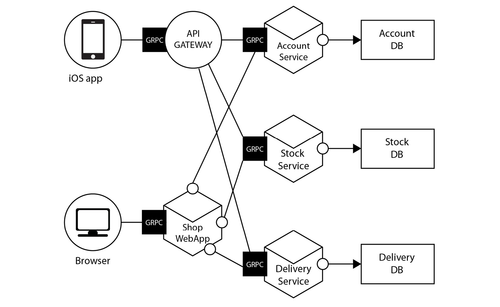
Figure 7.1 – An example of a distributed system
Distributed systems have grown in complexity over the years, but paradoxically there has never been a better time to build and run one. Due to cloud companies such as Amazon Web Services (AWS), Cloudflare, and DigitalOcean, getting started with complex systems is available to anyone for free where there used to be a very high barrier to entry.
A distributed system usually has the following characteristics:
- Scalable: The system can grow as workloads increase. For example, if your customers are heavily based in the United States, you may see large traffic between 9 A.M. and 5 P.M. in the daytime, but low traffic in the evening. You may choose to scale up and down your system to match these patterns and optimize for costs.
- Fault-tolerant: If one piece of our system fails, it shouldn’t all fail. Imagine you are trying to pay for a product on a website and it keeps saying Oops, something went wrong, please try again later; however, the rest of the site remains fully functional. You can add things to your basket, browse other products, and leave reviews. This is fault tolerance at work; the payment system being down does not take the rest of the sit-down.
- Transparent: Our system appears as a single unit to our end users; they do not need to worry about the underlying implementation.
- Concurrent: Multiple activities can happen at the same time within our system.
- Heterogenous: This is a fancy word that means we can use a variety of servers, programming languages, and paradigms. For example, we may run some servers using Windows, and some using Linux. Some parts of our system may run in Kubernetes, while some might run on Raspberry Pi. Some of the systems may use an event-driven model and some might be synchronous. Some engineers may use Golang and some Python.
- Replicated: Information is often replicated to enable fault tolerance. For example, one common pattern is to have a primary Postgres database and a secondary read-only version that is replicated from the primary for redundancy.
You often must make trade-offs in the preceding categories to build a distributed system. A famous theorem taught in computer science classes is called the CAP theorem. The CAP theorem states you must pick two of the following categories to make guarantees about, and the third you must accept will suffer. These are:
- Consistency: Every read receives the most up-to-date information or an error.
- Availability: Every request receives a non-error response, but it may not receive the most up-to-date information.
- Partition tolerance: The system continues to operate even if there are network issues happening (such as packets being dropped). In the event of a failure here, the system designer must make a choice between:
Let’s look at one useful application for the CAP theorem: choosing a database for our system.
CAP theorem and databases
You’ll often see CAP theorem trade-offs used for describing databases. For example, Mongo is a popular NoSQL database. Mongo is described as a CP database. This means it delivers consistency and partition tolerance, but it does so at the expense of availability.
Mongo has a single primary node. This node must receive all write operations. Once persisted, these new writes are replicated to secondary nodes. By default, clients read from the primary node to ensure they get the most recent information, but they can also read from a secondary node if configured to do so.
If the primary goes down, a secondary with the most recent data is promoted. The database is unavailable at this time. Once all the secondaries catch up, the database system becomes available again. Here is a diagram of how replication works in a Mongo cluster:

Figure 7.2 – Mongo replication
Alternatively, Cassandra is an AP database. Cassandra prioritizes availability and partition tolerance but sacrifices consistency. Cassandra has no primary, and you can write to any of the nodes. Cassandra claims that it can survive the complete loss of a data center and has no single point of failure (SPOF) due to all the nodes being the same. You can also scale out Cassandra horizontally as it uses something called “consistent hashing”. In consistent hashing, keys are distributed in an abstract hash ring that is not dependent on the number of nodes we currently have. A simplified example of how this works is provided here:
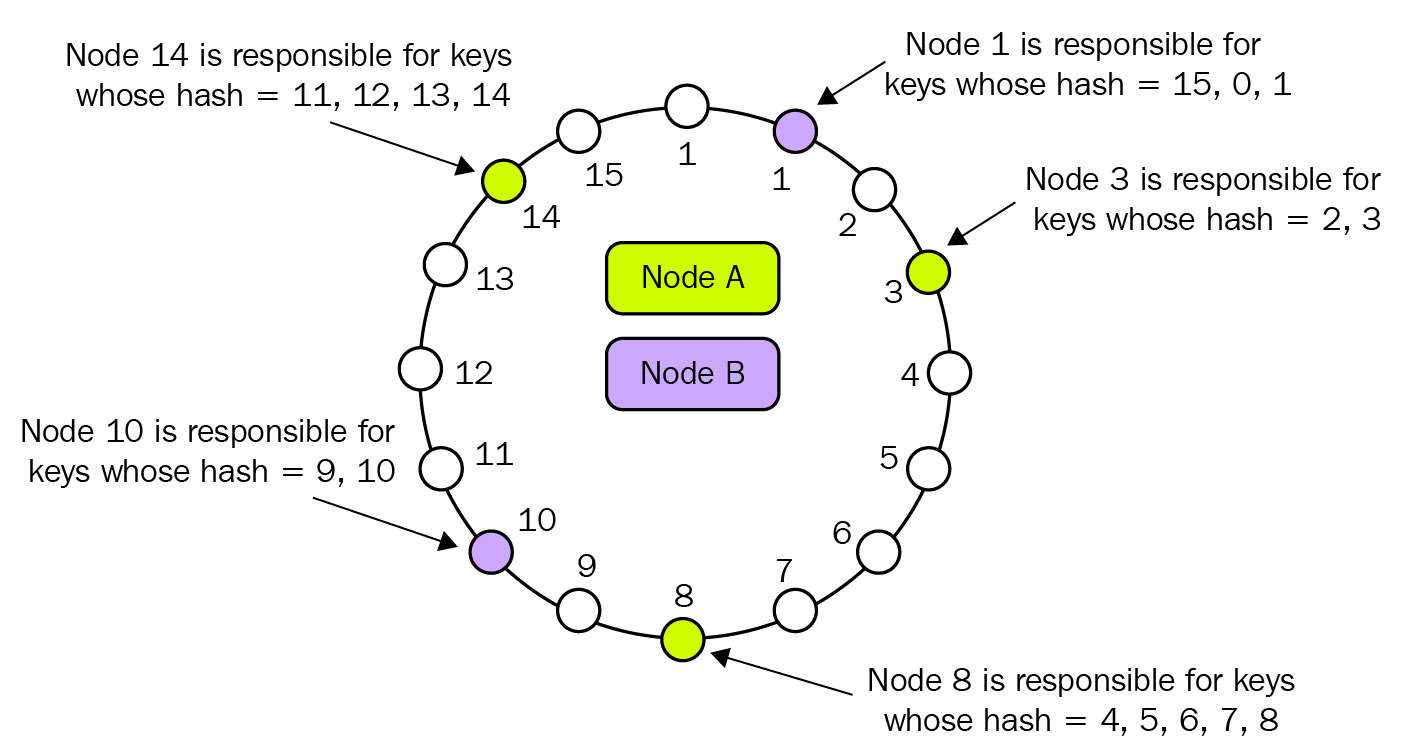
Figure 7.3 – Cassandra replication
As you have probably figured out, Cassandra works very differently from the traditional databases we are used to. It can be complicated to understand and therefore takes some research and experimentation to get comfortable with. However, it can also be very powerful and is widely used by huge companies.
The CAP theorem is a complex topic that entire books could be written about. I have included some further reading at the bottom of this chapter for those who wish to explore it more.
To help us build systems that can achieve all the things we have just discussed, we use various architecture patterns. Let’s look at some of them now.
Distributed system patterns
Distributed systems can get complex quickly. Over the years, many patterns have emerged to help us manage and thrive in this complexity. We will explore some of them next.
CQRS
Those who know a little about CQRS might be surprised that one of the first mentions of it in a book about DDD is in the distributed system section. Let’s dig into what it is, and then we can revisit this point.
In traditional systems and the monolithic system we built in Chapter 5, Applying DDD to a Monolithic Application, we use the same data model and repository to create and read a database from our database. This can work well in a lot of use cases, but as systems develop complexity, it can be hard to manage all the queries and mapping between the data and service layer. Furthermore, systems often have different requirements for reading and writing. For example, a system for capturing analytics might write a lot more than it is read. It could make sense to treat these concerns differently.
Let’s take the simple example of a website. When a user views the website, the system might use a query model to get the relevant data to show to the user. If the user does some sort of action to change something (perhaps update their shipping address), the system will issue a command to make this change. A diagram of how the system might look is shown here:
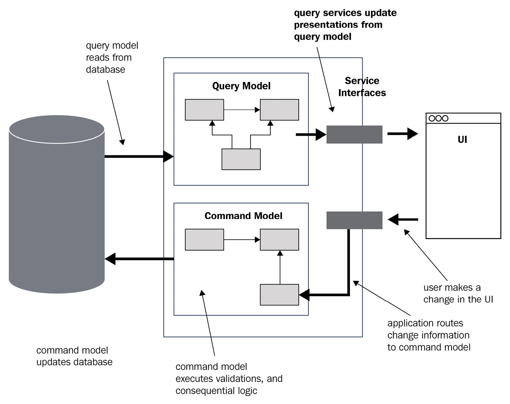
Figure 7.4 – CQRS in action
CQRS is not necessary for DDD, but the sort of complex systems that benefit from DDD may also benefit from exploring CQRS; both are there to help you model and manage complexity.
Bertrand Meyer, the creator of the Eiffel programming language and credited with creating the CQRS pattern, suggests that we follow a few simple rules while implementing CQRS. These are as follows:
- Every method should be a command that performs an action or a query that answers a question. However, no method should do both.
- Asking a question should not change the answer; queries should not mutate.
For object-oriented (OO) languages such as Java, these rules are extended to include the following:
- If a method modifies the state of an object, it is a command. It should return void.
- If a method returns a value and its query, it is answering a question. They should not modify the state of an object.
We can adapt these to Golang, as follows:
- If a method modifies the state of the receiver struct or database, it is a command and should return an error or nil
- If a method returns a value, it should not modify the database or its receiver struct
It might be tempting to try to enforce this through an interface, as follows:
type Commander interface {
    Command(ctx context.Context, args ...interface{}) error
}
type Querier interface {
    Question(ctx context.Context, args ...interface{}) (interface{}, error)
}
But I really do not recommend this. We have lost all benefits of Go’s type system here, and our function names give little insight into what the command/query will actually be doing.
So, why is CQRS mentioned in the distributed system section of this book? In monolithic systems, I rarely believe the CQRS pattern is the best option for managing complexity unless implemented perfectly. However, it can work fantastically well for event-based systems (which we talk about a little more next). Commands are a great way to model domain-event emission (for example, writing to Kafka).
EDA
EDA is a pattern in which our distributed system produces, detects, and responds to events. An event is defined as a significant change in state. In domain-driven systems, input and output (I/O) events travel via a port on a protocol suited to the transport that matches the message bus you are using. For example, RabbitMQ uses the Advanced Messaging Queuing Protocol (AMQP) protocol. We will talk about message buses in the message bus section of this chapter.
Events are typically made up of two parts: an event header and an event body. The event header will usually contain some meta-information about the message. For example, it might include a timestamp of when the message was emitted, the system that emitted it, and a unique identifier (UID) for that specific message. The body usually contains information about the state that changed. An example body could look like this:
{
"event_type": "user.logged_in",
"user_id": 135649039"
}
In the preceding example, we have used JSON format, but some other formats popular for defining message schemas are Protobuf, Apache Avro, and Cap’n Proto.
In event-driven systems, there will be a whole variety of messages for varying purposes being emitted. For example, they could be logging, measuring system health, or used for dynamically provisioning resources. The message type we are interested in regarding DDD is domain events. For example, we might be interested in a message called user.loggedIn or purchase.failed. These example domain events would be output by one of the microservices in our distributed system and ingested by another.
These domain events might have significance in one specific bounded context but mean nothing to another. This is to be expected and encouraged; there is no expectation that every system is interested in every domain event. If a domain event is interesting within our bounded context, we can transform it into a shape that makes sense for our domain model and take action on it.
Individual domain events might not mean too much by themselves, and it might be they represent only a small part of longer-running tasks. We therefore might need to chain multiple events and systems together to yield the outcome we want. An example is provided here:
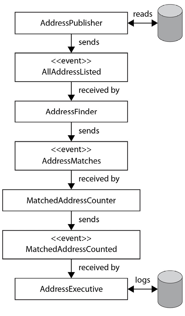
Figure 7.5 – A pipeline of domain events
In this example, you can see how a long-running process starts with us initiating a long-running task that goes through a series of pipeline steps before it becomes useful at the end.
Pipelining such as this is powerful as the system is very flexible. For example, it might be that another system is interested in the addressesMatched event and can subscribe from there. It might also be in the future we want to adapt this pipeline to add a new business requirement. For example, maybe we have a requirement that if addressesMatched < 500, we trigger a smaller more lightweight process. This would be very easy for us to add.
One major problem event-driven systems face is the distributed nature of the data. For example, if I have a long-running process such as that defined previously, and someone changes their address mid-way through the process, how do we handle that? What if the change they made means we need to cancel our process to ensure the business requirements remain enforced in our system? Let’s explore a couple of patterns for dealing with this problem.
Dealing with failure
Earlier in this chapter, we discussed the CAP theorem and the concept of having to choose which compromises in our system to make. Alongside this, we must expect that our distributed system will fail due to both factors outside of our control and edge-case failure modes that we accept can happen from time to time, but we accept that risk in favor of delivery speed. Next, we will discuss some patterns we can put in place to mitigate some of these failures.
Two-phase commit (2PC)
As we discussed earlier, consistency is equally (if not more so) important in a distributed system as it is in a monolithic architecture. However, it is near impossible to create distributed transactions and commit atomically. One approach to solve this is to split our work into two phases:
- Preparation phase: We ask each of our sub-systems if it can promise to do the workload we want to complete.
- Completion phase: Tell each sub-system to do the work it just promised to do.
In the preparation phase, each of the sub-systems will complete whatever action is necessary to ensure it can keep its promise. In a lot of situations, this is putting a lock around a resource. If any of the participants cannot make this commitment, or if a specified time interval passes without hearing from the coordinator, the workload is aborted.
A diagram of how this looks conceptually is provided here:
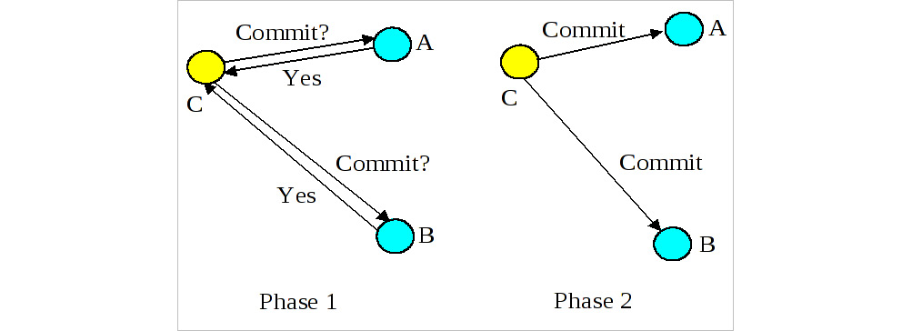
Figure 7.6 – 2PC in action
2PC is a useful pattern to be aware of when building a domain-driven system. Remember—our job as engineers, and especially those who have committed to working in a domain-driven way, is to ensure the system reflects the business domain model as closely as possible. If something goes wrong, the 2PC has a compensating control (the rollback) that helps to ensure that business invariants are not broken. The biggest disadvantage of the 2PC is the fact that it’s a blocking protocol. This means in the best case we lose some of the concurrency ability within our system, and in the worst case, no work can be completed at all until the lock is released (either manually or when a pre-specified threshold expires). There are a few other patterns that aim to improve on this, one of which is the saga pattern.
The saga pattern
The saga pattern aims to allow us to achieve consistency within a distributed system without preventing concurrency.
The basic principle of the saga pattern is a simple one; for each action we take within our system, we also define a compensating action that we call in the event we need to roll back.
Let’s look at an example. The following diagram shows the flow of an order being created through to customer notification:
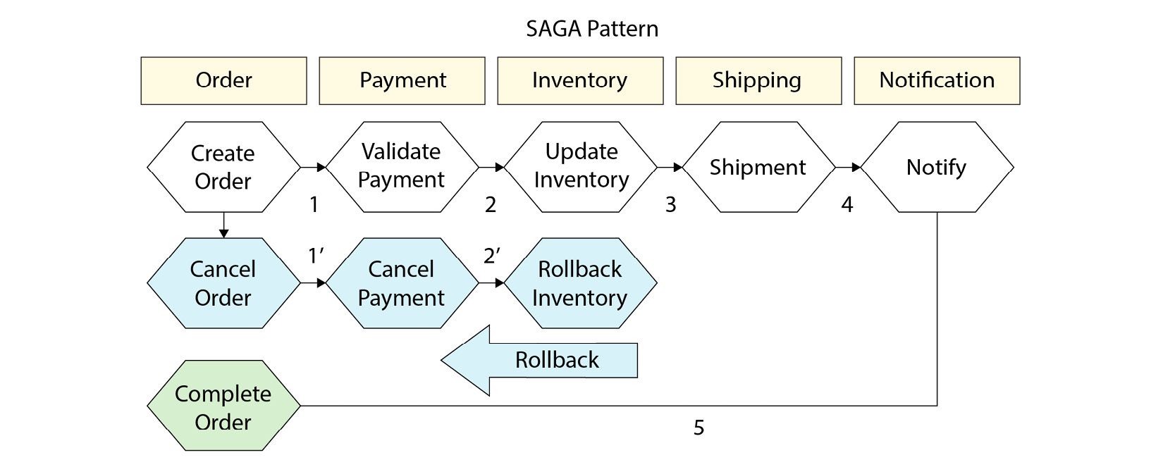
Figure 7.7 – What a saga pattern might look like for an e-commerce system
The blue hexagons represent the happy path. If all goes well, we will simply move from step 1 through to 5 where our order is complete. However, if the system fails at any point, we roll back all the actions before it. Therefore, if the update inventory failed, we would call rollback inventory, cancel payment, and cancel the order. If all these steps successfully resolve or roll back, we should have a consistent system.
The obvious flaw here is this: what if our compensating controls fail too? This is where we can combine the saga pattern with an EDA (that we mentioned previously) and emit an event for compensating control. This means it can be retried by consumer services at their own pace and using their own patterns.
Implementing a resilient saga pattern is challenging and beyond the scope of this book. However, a naïve implementation that can hopefully serve as a useful reference and starting point might look like this:
package chapter7
import "context"
type Saga interface {
   Execute(ctx context.Context) error
   Rollback(ctx context.Context) error
}
type OrderCreator struct{}
func (o OrderCreator) Execute(ctx context.Context) error {
   return o.createOrder(ctx)
}
func (o OrderCreator) Rollback(ctx context.Context) error {
   //Rollback Saga here
   return nil
}
func (o OrderCreator) createOrder(ctx context.Context) error {
   // Create Order here
   return nil
}
type PaymentCreator struct{}
func (p PaymentCreator) Execute(ctx context.Context) error {
   return p.createPayment(ctx)
}
func (p PaymentCreator) Rollback(ctx context.Context) error {
   //Rollback Saga here
   return nil
}
func (p PaymentCreator) createPayment(ctx context.Context) error {
   // Create payment here
   return nil
}
type SagaManager struct {
   actions []Saga
}
func (s SagaManager) Handle(ctx context.Context) {
   for i, action := range s.actions {
      if err := action.Execute(ctx); err != nil {
         for j := 0; j <= i; j++ {
            if err := s.actions[j].Rollback(ctx); err != nil {
               // One of our compensation actions failed; we need to handle it (perhaps by emitting a message to a
               // a messagebus.
            }
         }
      }
   }
}
In the preceding code block, we declare an interface called Saga. Anything that has an Execute function that returns an error and a Rollback function that returns an error satisfies our Saga interface. For demonstration purposes, I have declared OrderCreator and PaymentCreator structs that satisfy this interface. Finally, I create a struct called a SagaManager and create a Handle function.
In this Handle function, I range over all the registered actions. If none of them returns an error, we can assume the saga is complete and our system is in a consistent state. If one of them fails, we call Rollback on each of the actions we executed so far. In the simple example, we do not take an action if the rollback fails, but you may want to trigger an alert in this instance to notify an engineer that the system is not in a consistent state, or perhaps emit an event to a message bus that allows you to retry the rollback later.
We have used the term message bus a few times so far, so let’s review what we mean by that phrase.
What is a message bus?
The term message bus originates from enterprise architecture patterns. The pattern aims to:
- Create a common data model and command set shared through a set of shared interfaces
- Allow decoupling of applications so that old ones could be taken away and new ones added with minimal disruption
A shared file could technically satisfy the definition of a message bus (and that is kind of what Kafka is).
In modern software development, we have many different flavors of message buses at our disposal. Purists may argue that some of the tools suggested here aren’t technically message buses—they are message queues. The distinction is that the definition of message bus does not say anything about guaranteed ordering or other queue-like semantics. Truthfully, I think it’s unimportant, and it’s more important to ensure you pick the correct tool for what you are trying to achieve. Next, I have included a few popular message bus options and a short summary of why you might or might not use them. I hope this is useful as a jumping-off point for further discovery.
Kafka
Kafka is open sourced by the Apache Software Foundation (ASF). It was originally created by Linkedin and has become incredibly popular due to its versatility in use. Kafka can be scaled to achieve millions of requests per second and is popular at internet-scale companies such as Microsoft and Cloudflare due to its ability to scale and keep latency low, while also being fault-tolerant.
A typical Kafka architecture looks like this:
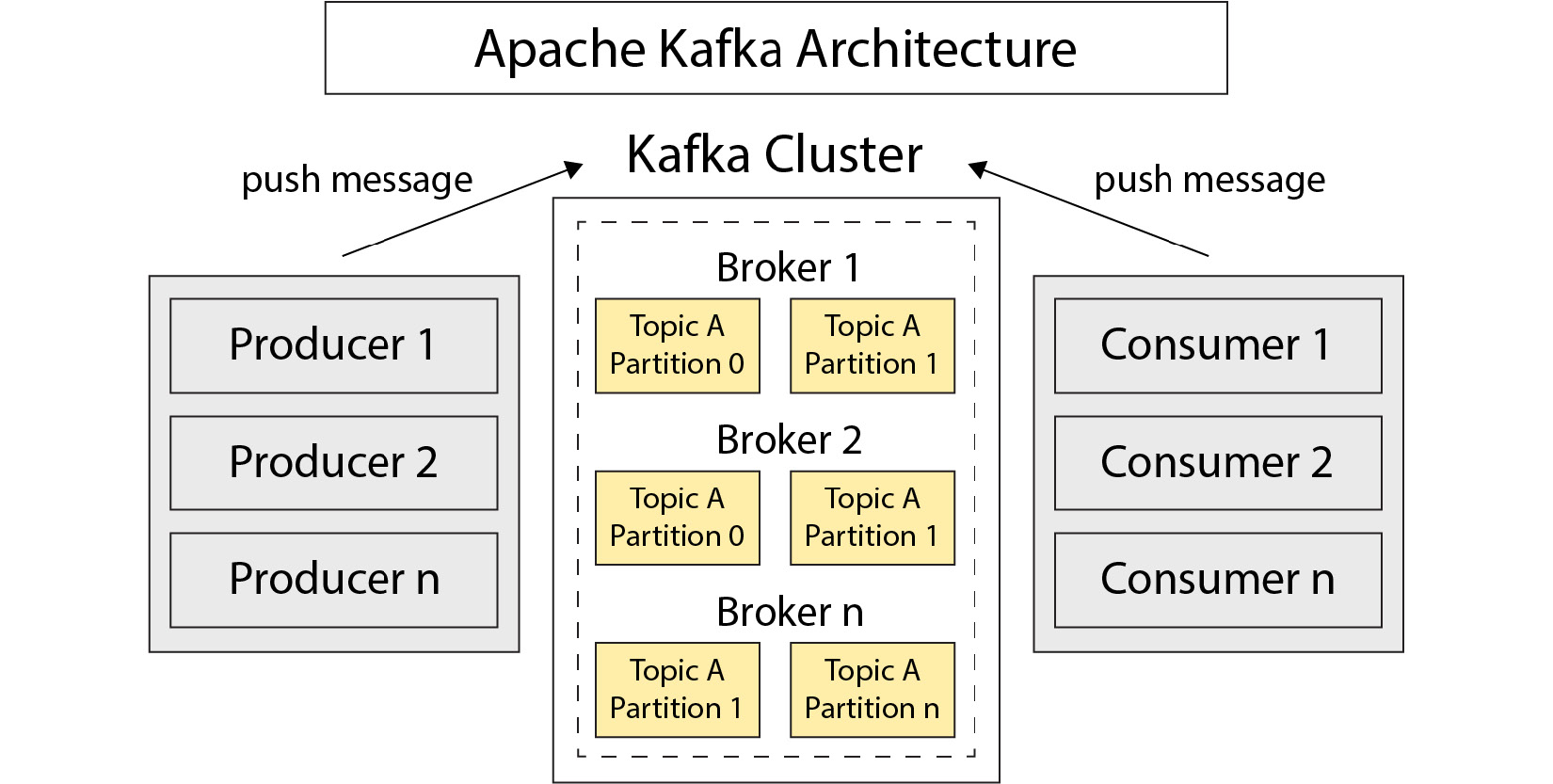
Figure 7.8 – Architecture of Kafka
Firstly, we have a broker. This is responsible for storing messages sent in topics. Topics can be split into many partitions.
Producers are services that connect to Kafka to send messages. They will specify a target a topic and a partition.
Consumers subscribe to topics and partitions to read messages. We can group multiple instances of a consumer together for scalability reasons. They will work together to read all messages from a topic in what is called a consumer group. Services can be both consumers and producers. For example, you might consume from one topic, do some processing, and produce to another.
One challenge of Kafka is that you must know quite a lot about it to use it effectively, and it’s easy to make mistakes that can have dire consequences for your application (for example, you can very easily cause messages to be delivered out of order if you use the wrong partitioning strategy). Furthermore, monitoring it can be difficult, and running your own cluster is not for the faint of heart.
RabbitMQ
RabbitMQ is also an open source queuing system based on the AMQP protocol. It is easy to get started with and conceptually is simple. Messages are sent by producers to an exchange, which forwards them to one or many queues. Once a message has been read from a queue and acknowledged by a producer application, it is consumed and will never be received again. RabbitMQ comes packaged with a nice UI that gives you some visibility into what is happening.
Here’s an example overview of the Admin dashboard:
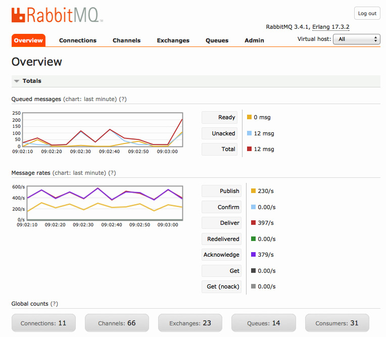
Figure 7.9 – RabbitMQ Admin dashboard
RabbitMQ’s architecture shares some similarities with Kafka’s:
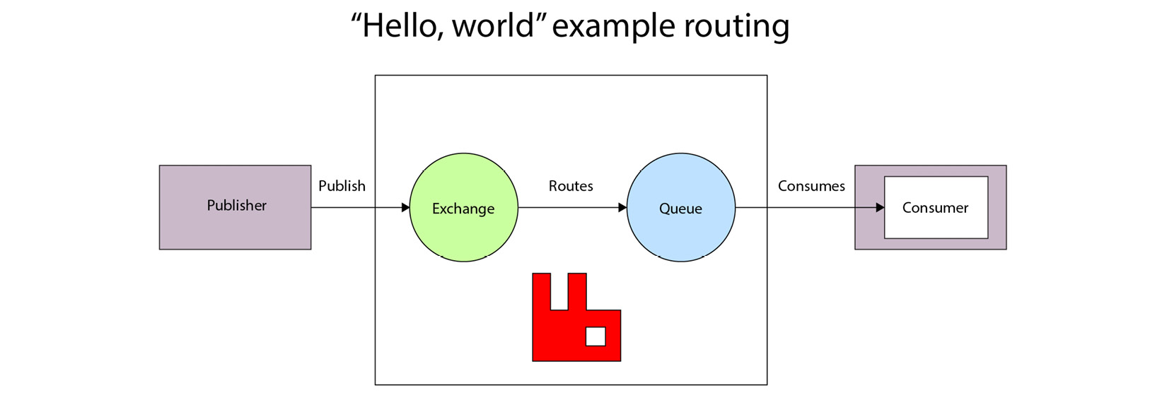
Figure 7.10 – Architecture of RabbitMQ
The publisher sends messages to an exchange. Based on the routing key, it is sent to a specific queue where is it picked up by a consumer application to process.
The disadvantages of RabbitMQ are mostly that it doesn’t scale quite as well or as easily as Kafka. It also only offers a subset of the features that Kafka does. In my experience, as companies scale both in terms of workloads and teams, they start to want a richer feature set and usually start exploring migrating to Kafka.
NATS
Neural Autonomic Transport System (NATS) is an open source streaming system written in Golang. This makes it a great option for learning more about how some of these technologies work under the hood as the code is very readable.
NATS has some similarities with Kafka, in that you publish messages to subjects, and they are consumed by subscribers. One nice feature of NATS is the ability to wildcard match on topics such as those shown here:

Figure 7.11 – Architecture of NATS
The biggest thing you need to consider when using NATS is its durability. NATS guarantees at-most-once delivery, which is to say your message might never be delivered at all. However, in return for this, you get an incredibly simple-to-run streaming system. Due to how lightweight it is and its speed, it is commonly used for IoT use cases.
Summary
The goal of this chapter was to highlight that DDD is not the entire story, and there are patterns and tools out there that can help you navigate the complexity you may experience as you work on bigger systems. We barely scratched the surface of most of these topics, so I have included further reading next that will hopefully help you explore some of these topics deeper if they interest you.
Further reading
- CAP theorem: https://en.wikipedia.org/wiki/CAP_theorem
- Using Kafka at scale: https://blog.cloudflare.com/using-apache-kafka-to-process-1-trillion-messages/
- Getting started with RabbitMQ: https://www.cloudamqp.com/blog/part1-rabbitmq-for-beginners-what-is-rabbitmq.html
- NATS overview: https://docs.nats.io/nats-concepts/overview