


Migration planning
This chapter provides guidance for configuration planning. The topics covered are:
Preparation and installation
In most cases, Server Time Protocol (STP) configuration planning involves the migration from an External Time References (ETR) network to an STP-only Coordinated Timing Network (CTN). Although it is recognized that there can be an intermediate phase during which servers in both ETR timing mode and STP timing mode will coexist in a Mixed CTN, the final stage is expected to be an STP-only CTN. A new configuration that is not migrating from an ETR network can be directly configured as an STP-only CTN.
Before starting a migration, you must complete the installation tasks that are associated with hardware and software components. It is important to complete all hardware and software tasks for the intended Mixed CTN prior to enabling STP.
Hardware installation
To make the servers STP-capable, hardware maintainace change levels (MCLs) must be installed on the servers that will be configured in a Mixed or STP-only CTN. In essence, this means that you install all MCLs that are available for all STP-capable servers and coupling facilities (CFs):
•The z990 and z890 must be at EC Driver level 55K or later, in addition to the latest MCLs that are available for the driver. STP on z990 or z890 does not support using an Network Time Protocol (NTP) server as an External Time Source (ETS).
•The z9 EC and z9 BC must be at EC Driver level 67L or later, in addition to the latest MCLs. The NTP server is supported as an ETS.
•The z10 EC and z10 BC must be at Driver level 76D or later, in addition to the latest MCLs. The NTP server is supported as an ETS.
Table A-1 shows the correspondence between the driver level and the Support Element (SE) console application level for servers that can install the STP feature.
Table A-1 EC Driver and SE console application levels
|
Server
|
EC driver
level
|
Support Element
console application
|
includes NTP
client support
|
HMC
Application
|
|
z10 EC, z10 BC
|
79F
|
2.10.2
|
Yes
|
2.10.2
|
|
z10 EC, z10 BC
|
76D
|
V2.10.1
|
Yes
|
V2.10.1
|
|
z9 EC, z9 BC
|
67L
|
V2.9.2
|
Yes
|
V2.9.2
|
The Hardware Management Console (HMC) Application level must be equal to or higher than the level of the Support Element console that it manages.
STP functions cannot be used until the STP feature (Feature Code 1021) is installed. The feature should be installed on any server or coupling facility that is to be used in a Mixed or STP-only CTN. The STP feature is installed via the server Support Element without disruption to current operations. After the MCLs are installed, all eligible servers are STP-capable servers.
After installation of the STP feature, the server can be configured for STP. Note the following:
•The System (Sysplex) Time task is available on the SE and HMC to configure a server to use STP.
•Coupling facility partitions automatically recognize the new functions. However, z/OS system images must be IPLed.
Sysplex Timer considerations
The Sysplex Timer's Licensed Internal Code (LIC) has been upgraded to support using STP in a Mixed Coordinated Timing Network (Mixed CTN). The required Sysplex Timer LIC is shipped along with the STP feature, and must be installed by the IBM Service Support Representative prior to migrating from a Sysplex Timer-based ETR network to any Coordinated Timing Network.
The Sysplex Timer provides the timekeeping information in a Mixed CTN. The Sysplex Timer consoles continue to be used for all timing-related functions, such as initializing time, scheduling daylight saving time, adjusting time, and so forth. Plan to keep access to the Sysplex Timer consoles for as long as the Sysplex Timer remains operational in the timing configuration.
Continuous availability of timers
The two timers should be physically separated. The better the separation, the lower the probability that an environmental failure will affect both timers. Note the following considerations:
•If an external time source is used, an ETS should be attached to each timer for continuous ETS availability.
•An active and a stand-by console should be configured.
•Each timer unit should be connected to a separate AC power source.
•When extenders are used, connect at least one pair of the extenders used for the CLO links to a power source that is separate from the power source used by the primary Sysplex Timer. Doing so greatly improves the probability that the OLS from the primary Sysplex Timer will be received by the secondary Sysplex Timer.
•If available, protect the power connections with an uninterruptable power supply (UPS) for each Sysplex Timer and extender.
•Route each CLO link between timers and each fiber link between timer and CPCs across separate paths.
Availability of an STP-capable HMC
Either upgrade an existing HMC or install a new HMC capable of running the HMC application V2.9.2 or later. The HMC Application level must be equal to or later than the level of that Support Element console that it manages (Table A-1 on page 162).
All servers in the CTN must be defined to the HMC. We strongly recommend this even if the servers are in a multi-site configuration. If at least one HMC does not have connectivity to all servers, it is not possible to freely configure all roles in the CTN.
The HMC workstation is a closed environment dedicated to the HMC Application. No other application can be installed.
z/OS preparation and installation
Even though z/OS supports STP, additional maintenance may be required. STP-related maintenance may be required for all z/OS systems that require time synchronization with a z/OS image or CF on a server configured in a Mixed or STP-only CTN. In a sysplex configuration, if any coupling facility or z/OS image is running on an STP-configured server, STP maintenance may be required on all z/OS images in the sysplex.
A re-IPL is required for the z/OS maintenance to take effect. Before performing the IPL, the CLOCKxx member in the PARMLIB might need to be edited to contain the required STP statements (see 2.5.2, “CLOCKxx” on page 59).
|
Important: If the z/OS maintenance is applied before installing the STP feature, z/OS must be re-IPLed after the STP feature is installed.
|
z/OS images that do not require multisystem time synchronization can be at any supported release regardless of the timing mode of the server.
PSP buckets
Consult the PSP Buckets for STP-related maintenance. Look in the associated hardware Preventive Service Planning subset. The upgrade is xxxxDevice and the subset is xxxx/ZOS where xxxx is one of the machine types that supports STP (that is, 2094, 2096, 2084, or 2086).
To simplify the identification of PTFs needed to support Server Timer Protocol, a functional Preventive Service Planning (PSP) bucket has been created. Use the Technical Help Database for Mainframe Preventive Service Planning Buckets and the Enhanced PSP Tool to reconcile the recommended service for STP and the hardware device against your systems’ target zones. The database is available at the following Web site:
This Web site provides a search capability, as well as pull-down lists for types of PSP buckets. Scroll to the “Find the bucket by Type, Category, and Release” heading, then select Function for the Type field and STP for the Category field.
Server roles in an STP-only CTN
It is important to decide what role each server in the CTN will play, as discussed here:
•One server will be the Preferred Time Server and should be assigned as the Current Time Server (CTS, stratum 1).
|
Note: Only the PTS can automatically re-take over the CTS role after a recovery action when BTS has taken over as the CTS.
|
•Assign a second server, if available, the role of the Backup Time Server (BTS).
•Assign a third server, if available, the role of Arbiter. The Arbiter provides additional means for the BTS to determine whether it should take over as the Current Time Server in the event of planned or unplanned outages.
Do not make the choice of Preferred and Current Time Server lightly. This is the preferred server for good reason. Keep in mind the following considerations when assigning this role:
•The location of the server
In a multi-site configuration, is the Preferred Time Server located in the most important site (if relevant)? Is it a server running critical production? Is the server part of a disaster recovery setup?
|
Note: If disks are being mirrored, locate the PTS in the same site as the primary disk subsystems.
|
•The technology level of the server
A new STP function will be introduced to the latest technology, not necessarily to older server generations. For example, if NTP client support is planned, a z990 or z890 cannot be chosen as PTS or BTS.
•Maintenance considerations
A server that requires frequent scheduled maintenance is not the best choice. Disruptive actions are not permitted on a server that is assigned the role of Current Time Server. The CTS role must be moved in advance.
•Connectivity considerations
– With three or more servers, the PTS, BTS, and Arbiter must connect to each other with coupling links forming a triangle.
– The BTS connectivity to other servers should be such that all servers remain synchronized when the PTS fails and the BTS takes over the CTS role.
– All stratum 3 servers should connect to at least two stratum 2 servers. This allows the stratum 3 server to continue in the synchronized state in the event that one of the stratum 2 servers fails or is unavailable due to maintenance. Since STP does not support four stratum levels, a stratum 4 server would be placed in the unsynchronized timing state (stratum 0).
– Also pay attention not to exeed the maximum number of CF links that can be connected to a single CEC when planning for additional connectivity.
– A standalone coupling facility typically has coupling link connectivity to other servers requiring time coordination. This existing connectivity can be exploited for STP message exchanges without having to deploy additional coupling links. However, you must also pay attention to the connectivity rules listed above and the best practices recommendations for the reassignment of servers listed in , “Plan for high availability” on page 166.
– A standalone coupling facility does not produce z/OS messages for operations or interception by automation routines. Although CTN information is available from z/OS images on other servers, not all information specific to the server role assigned to the coupling facility is available. This includes:
• Information messages at IPL or interrupt time, or Display ETR output that specifically identifies a server role. However, CTN information is available from other z/OS images in the CTN.
IEA380I THIS SYSTEM IS NOW OPERATING IN STP TIMING MODE.
IEA381I THE STP FACILITY IS NOT USABLE. SYSTEM CONTINUES IN LOCAL TIMING MODE
IEA386I TIMING STATUS SYNCHRONIZATION MODE
NUMBER OF TIMING LINKS=nn
THIS IS THE PREFERRED / BACKUP / ARBITER SERVER
THIS SERVER HAS NO LINK TO THE PREFERRED TIME SERVER
THIS SERVER HAS NO LINK TO THE ARBITER SERVER
THIS SERVER HAS ONLY A SINGLE SOURCE OF TIMING SIGNALS
IEA390I TOD CLOCKS DYNAMICALLY ADJUSTED TO MAINTAIN STP SYNCHRONISM.
• Warning messages identifying a condition being associated to a given server. If the condition being raised relates to connectivity between two servers, the information might be available to a z/OS system image at the other end of the link. However, if both ends of the link are CF partitions, no warning message is available to the user.
IEA382I THIS SERVER HAS ONLY A SINGLE LINK AVAILABLE FOR TIMING PURPOSES
IEA383I THIS SERVER RECEIVES TIMING SIGNALS FROM ONLY ONE OTHER NETWORK NODE
IEA388I THIS SERVER HAS NO CONNECTION TO THE BACKUP / ARBITER
IEA394A THIS SERVER HAS LOST CONNECTION TO ITS SOURCE OF TIME. IF THIS EVENT OCCURRED ON SOME, BUT NOT ALL NETWORK SERVERS, THE LIKELY CAUSE IS A LINK FAILURE. TO FIX, ENSURE THAT EACH AFFECTED SERVER HAS AT LEAST ONE CORRECTLY CONNECTED AND FUNCTIONAL LINK. IF THIS EVENT OCCURRED ON ALL NETWORK SERVERS, THEN THE LIKELY CAUSE IA A TIMING NETWORK FAILURE. TO FIX, REFER TO THE MESSAGE IEA394A DESCRIPTION IN MVS SYSTEM MESSAGES. AFTER FIXING THE PROBLEM, REPLY "RETRY" FROM THE SERVICE CONSOLE (HMC). IF THE PROBLEM WAS NOT CORRECTED, THIS MESSAGE WILL BE REISSUED AND YOU MAY TRY AGAIN. REPLY "ABORT" TO EXIT THE MESSAGE LOOP. PROABLE RESULT: 0A2-158 WAITSTATE.
•Recovery considerations
Keep in mind that STP recovery and sysplex recovery are two different things. When the CTS fails, not only STP must recover, but also z/OS-images or coupling facilities, or even both, are unavailable, if they were located on the failing CEC. Therefore, even if all remaining servers stay in synch due to STP recovery, recovery actions for the sysplex might still be required.
Once these points have been considered for the PTS/CTS, a similar review should be made for the Backup Time Server. In a two-site configuration the PTS and BTS should be in different sites.
The Arbiter must be assigned to a server that has coupling connectivity to both the PTS and the BTS. Also, for a two-site-configuration, the Arbiter must be in the same site as the PTS, unless specific reasons suggest otherwise (for example, GDPS with Freeze policy).
|
Note: No single recommendation for server role is appropriate for all possible situations. Each customer must evaluate which factors are important in his operational environment.
|
Plan for high availability
Regarding high availability:
•In a Mixed CTN there must be at least one STP-configured server connected to a pair of Sysplex Timers. The server steps to signals received from one of the Sysplex Timers.
•In order to avoid single points of failure, there should be at least two stratum 1 servers in a Mixed CTN (stepping to timing signals received from the Sysplex Timers) before configuring any additional servers that use STP messages for synchronization.
•A Mixed or STP-only CTN should be configured so that every stratum 3 server is attached to at least two stratum 2 servers. This allows the stratum 3 server to continue in the synchronized state in the event that one of the stratum 2 servers fails or is unavailable due to maintenance. Since STP does not support four stratum levels, a stratum 4 server would be placed in the unsynchronized timing state.
•Redundant coupling links should be configured between any two servers in the CTN. Whenever possible, CHPIDs should be defined in the access list for at least two partitions.
Also consider the possibility for timing-only links to be reassigned as coupling links, or vice versa. Timing-only links must be configured when a CF does not exist at either end of the coupling link. Re-assigning timing-only links as coupling links and vice versa can be done without disruption, as described in 3.5.1, “Migrating timing-only links to coupling links” on page 134.
•For installations with more than three servers, plan for which servers CFs will be reassigned the STP roles in case one of the servers will be unavailable because of an extended planned or unplanned outage. With the reassignment the servers should be in a fault-tolerant configuration again. This is especially critical for the PTS and BTS-roles. If no reassignment is done, a subsequent failure of the CTS would lead to a CTN-wide sysplex outage, because there is no other server to take over the CTS role. Thus, no STP-recovery can be done.
•If the Arbiter is unavailable because of an outage, the rules for Arbiter-assisted recovery still apply and the OLS is ignored. In this case it might be reasonable to either move the Arbiter role to a different server or (if that is not possible) to temporarily remove the Arbiter role from the CTN. For a two-site-configuration, also plan ahead which servers to reassign the roles in case a site failure occurs.
Migration paths
After the preparation and installation steps are completed, the migration to a Coordinated Timing Network (CTN) can begin.
Definition and configuration actions are performed from the Hardware Management Console using the System (Sysplex) Time task. When properly planned and executed, all operations are concurrent to server operations and nondisruptive to the z/OS images. Certain operations affect an individual server. Other operations affect all servers defined to the CTN. Figure A-1 summarizes the possible paths.

Figure A-1 Overview of possible migration paths
The installation of, or migration to, a Coordinated Timing Network is a combination of one or more of the four steps illustrated, as described here:
1. Migrate from an ETR network to a Mixed CTN, or from a Mixed CTN to an ETR network.
This is a local action, one server or CF at a time. Definition of the CTN ID in the first server creates the Coordinated Timing Network, and removal of the last server deletes the Coordinated Timing Network.
2. Migrate a specific server or CF from ETR to STP timing mode in a Mixed CTN, or vice versa, migrate from STP timing mode to ETR timing mode.
This a a local action, one server at a time.
3. Migrate a Mixed CTN to an STP-only.
The scope is global, and the action affects all servers and CFs defined in the Mixed CTN.
4. Migrate an STP-only to a Mixed CTN.
The scope of the migration is global for all servers and CFs in the STP-only CTN. The Preferred and Backup Time Servers both migrate from STP timing mode to ETR timing mode. For other servers in the CTN, timing mode changes can be requested individually.
The following sections present a selected set of examples to illustrate possible migration steps. Example A-1 lists the scenarios documented. Each scenario focuses on one part of the migration. Review all configuration rules and recommendations documented in earlier chapters.
Example: A-1 Migration examples
|
Section
|
Description
|
Page
|
Migration from an ETR network to a Mixed Coordinated Timing Network involves tasks that fall into the following broad categories:
•Preparation: tasks planned and implemented prior to enabling STP
•Installation: tasks that must be completed prior to configuring a Mixed CTN
•Activation: steps that will migrate the ETR network to a Mixed CTN
Considerations before activating an STP-only CTN
Before an STP-only CTN configuration can become active and servers can exchange timekeeping messages, consider the following:
•Assign the CTN ID for each server that must be in the CTN.
•Assign the Preferred Time Server and the Current Time Server.
The server that is assigned the role of the Current Time Server becomes the active stratum 1 when an STP-only CTN configuration becomes active. In most cases, the Preferred Time Server is assigned also to be the Current Time Server.
•Optionally, a Backup Time Server can be assigned. This avoids a single point of failure.
The role of the Backup Time Server is to take over the role of the stratum 1 server in the event of planned or unplanned outages affecting the Preferred Time Server. Only the Preferred Time Server or the Backup Time Server can be the Current Time Server (that is, the active stratum 1 server) at any instant of time.
•If the CTN configuration comprises three or more servers, assign an Arbiter.
Migration between an ETR network and a Mixed CTN
This section describes a migration from an ETR network to a Mixed CTN, and then going back from a Mixed CTN configuration to an ETR network.
Migration from an ETR network to a Mixed CTN
Example scenarios are introduced in order of increasing difficulty, starting with the simplest. This scenario assumes the following:
•All servers and CFs are STP capable and are already synchronized in an ETR network.
•Coupling links connectivity is already in place for Parallel Sysplex, and the existing links can be used for STP messaging.
•The HMC on the operations LAN has access to all servers (not shown in Figure A-2 on page 171). All servers in this example are located within a single data center.
This starting configuration is illustrated in Figure A-2 on page 171. The STP-capable servers CEC1, CEC2, and CEC3 are configured in an ETR network, synchronized by the Sysplex Timers. Logical partitions P1, P2, and P3 are z/OS images in a Parallel Sysplex, using internal coupling facilities on servers CEC1 and CEC2.
The objective is to migrate to a Mixed CTN with the following configuration:
•CEC1, CEC2, and CEC3 participating in the Mixed CTN.
•CEC1 and CEC2 still in ETR timing mode, connected to the Sysplex Timers. Having two servers connected allows for high availability.
•CEC3 switched into STP timing mode, synchronized to CEC1 or CEC2.
Figure A-4 on page 173 illustrates the target configuration. Note that the flexibility of the Mixed CTN allows for multiple variations, and this example only illustrates one possible example of what can be achieved. Other variations are possible.
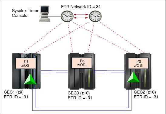
Figure A-2 Migration from an ETR network to a Mixed CTN: start scenario
Preparation
Complete the preparation tasks for the intended Mixed CTN prior to performing either the hardware or the z/OS installation tasks.
In this example there are no z/OS preparation tasks. However, you must install hardware MCLs on CEC1, CEC2, and CEC3. After the MCLs are installed, CEC1, CEC2, and CEC3 are STP-capable, but at this point STP is not enabled.
Installation
For installation:
•The STP feature must be installed on each server (CEC1, CEC2, and CEC3). Installation of the STP feature is concurrent.
After installation, the System (Sysplex) Time task is available on the SE and HMC to configure a server to use STP. The servers are now STP-enabled.
•Install the STP-related z/OS maintenance on all logical partitions (P1, P2, and P3), and update CLOCKxx, if needed.
A re-IPL of the z/OS images is required for the maintenance to take effect and for z/OS to recognize the newly installed STP feature.
Activation of the Mixed CTN
After the preparation and installation steps are completed, the CTN configuration and activation steps can be initiated. Perform all actions from the Hardware Management Console, using the System (Sysplex) Time task.
|
Note: When properly planned and executed, all operations from this point onward are concurrent to server operations and nondisruptive to the z/OS images.
|
Assign a CTN ID
The CTN ID is of the format [STP network ID] - [ETR network ID]. The ETR network ID already assigned to the ETR network should not be changed because it reflects the existing Sysplex Timer configuration. Only the STP network ID portion of the CTN ID should be changed.
•In this example, the STP ID selected is ITSOPOK. The value is entered on each server so that the same CTN ID is assigned to CEC1, CEC2, and CEC3.
•When completed, all servers are defined to a Mixed CTN with CTN ID = [ITSOPOK] - [31]. All servers are STP-configured. They are still connected to the Sysplex Timer and running in ETR timing mode (Figure A-3).

Figure A-3 Migration from an ETR network to a Mixed CTN: all servers in ETR timing mode
Migrate a server to STP timing mode
This step can be considered as optional and should not be used for the last (or preferably the last two) servers in the Mixed CTN to avoid losing the clock source for z/OS images with STPMODE YES or ETRMODE YES. If the Mixed CTN consists of one or two servers only, the next step might be to continue the migration to an STP-only CTN, which is described in , “Migration between a Mixed CTN and an STP-only CTN” on page 175.
Since the Mixed CTN has been created the user may want to switch an individual server to STP timing mode. However, this step does not migrate into an STP-only CTN. It simply switches a server into STP timing mode, forcing this individual server to use STP messaging through existing coupling links.
|
Important: The user should not disable the ETR ports on the last stratum 1 server because this removes the time source for the entire Mixed CTN.
|
In our example, the next step is to change the timing mode on CEC3 from ETR timing mode to STP timing mode. We consider this step because there are still two other servers (CEC1 and CEC2) connected to the Sysplex Timer and CEC3 does have coupling links to these servers. If the server being transitioned to STP timing mode does not have coupling links to at least one existing stratum 1 server the operation will not be successful> it will transition to local mode.
Follow these steps:
1. Verify that the STP connectivity is established between CEC3 and the two other servers. From the STP Status tab, the System Information section must show one line for each attached server.
2. From the ETR configuration panel of CEC3, disable its ETR ports.
3. CEC3 recognizes the loss of the Sysplex Timer signals and automatically switches to STP timing mode. CEC3 now synchronizes to either CEC1 or CEC2 using STP messages.
|
Note: This technique should not be used for the last two servers stepping to the ETR signals because the Sysplex Timer is the time source for the CTN. In a Mixed CTN, two stratum 1 servers should be configured in order to avoid a single point of failure.
|
The final configuration is shown in Figure A-4.

Figure A-4 Migration from an ETR network to a Mixed CTN: end scenario
Migration from a Mixed CTN to an ETR network
This scenario illustrates a migration going from a Mixed CTN back to an ETR network. This capability could be useful if, for example, you want to use a change window to do STP testing and then go back to a previous configuration concurrently. Figure A-5 provides an example. It assumes that all servers are already time synchronized using a Mixed CTN configuration. Logical partitions P1, P2, and P3 are three z/OS images participating in a Parallel Sysplex.
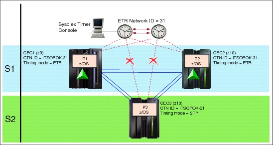
Figure A-5 Migration from a Mixed CTN to an ETR network: start scenario
The configuration planning considerations are:
•Since the servers are already in a Mixed CTN, there is no need to be concerned about enabling the hardware or software.
•When the migration to the ETR network is complete, the objective is to have all servers back into an ETR Network.
The CLOCKxx statements, such as ETRMODE and STPMODE, are available. Both are already specified as YES by default in all logical partitions participating in this sysplex example.
The resulting configuration is illustrated in Figure A-6 on page 175.
Preparation and installation
To prepare the hardware for migration, the CEC3 connections to the Sysplex Timer must still be in place. Ensure that the links are still available and that the Sysplex Timer ports are configured online on the Sysplex Timer console.
Activation
After the preparation and installation step is completed, the CTN configuration and activation steps can be initiated. All actions are now performed from the Hardware Management Console using the System (Sysplex) Time task.
When properly planned and executed, all operations from here on are concurrent to server operations and nondisruptive to the z/OS images.
Migrate a server to ETR timing mode
Enable the ETR ports. In this example, the CEC3 server ETR ports are enabled. This changes CEC3 from a stratum 2 to a stratum 1. It returns the server to ETR timing mode.
At this point, the CEC1, CEC2, and CEC3 are now in ETR timing mode. They still participate in a Mixed CTN with CTN ID = [ITSOPOK] - [31].
Modify the CTN ID
The next step is to modify the CTN ID. When both the STP network ID and ETR network ID are specified, the resulting CTN is referred to as a Mixed CTN:
•Modify the CTN ID on each STP-configured server. From the STP Configuration panel on the HMC, delete the STP ID portion of the CTN ID.
Do not change the ETR network ID, which identifies the ETR network.
•All servers in the configuration (CEC1, CEC2, and CEC3) are synchronized to the Sysplex Timer. They are part of the ETR network.
The migration from a Mixed CTN to an ETR network is complete. Figure A-6 shows the resultant ETR network.

Figure A-6 Migration from a Mixed CTN to an ETR network: end scenario
Migration between a Mixed CTN and an STP-only CTN
This section describes a migration from a Mixed CTN to an STP-only CTN, and then going back from an STP-only configuration to a Mixed CTN.
|
Note: Keep the sysplex timer and the STP-only CTN in sync until you are sure that no migration back from the STP-only CTN to a mixed CTN must occur. This can be accomplished by synchronizing both the ETR and the CTN to the same external time source. Before the reverse migration can successfully complete, the ETR and CTN must have the same time. Otherwise, adjustment steering will occur, which may take several days to complete.
|
Migration from a Mixed CTN to an STP-only CTN
This scenario is an example of a migration from a Mixed CTN to an STP-only CTN. This scenario assumes the following:
•All servers and CFs that are to participate in the CTN are STP-configured and already synchronized in a Mixed CTN.
There may be other non-STP-capable servers present, but they cannot be considered for the migration to an STP-only CTN. They remain either synchronized to a different ETR network or unsynchronized.
•All z/OS images that require time synchronization, such as those in a Parallel Sysplex, already have STP-related maintenance applied.
•Coupling link connectivity is already in place for Parallel Sysplex. The existing links are available for STP messaging and satisfy redundancy requirements. The STP messaging capability and redundancy was verified from the STP STATUS panel from each CEC, System Information section.
•The HMC on the operations LAN has access to all servers.
During a migration from a Mixed to STP-only CTN, the assigned Current Time Server inherits the time definitions from the ETR. No time initialization is required.
All the servers in this example are located within a single data center. Figure A-7 illustrates an example of such a configuration. All servers are synchronized in a Mixed CTN, and the CTN ID is [ITSOPOK] - [31].

Figure A-7 Migration from a Mixed CTN to an STP-only CTN: start scenario
When the migration to an STP-only CTN is completed, the objectives are to have:
•CEC1, CEC2, and CEC3 configured in an STP-only CTN.
The CTN ID contains an STP network ID part but no ETR network ID. A Preferred Time Server, a Backup Time Server, and an Arbiter are defined.
•CEC1, CEC2, and CEC3 are not synchronized to the Sysplex Timer.
All ETR ports on the servers are disabled. However, leave the ETR links in place for a certain period of time to allow for a backout plan. Depending on individual change management constraints, the ETR links can be disconnected once a migration back to a Mixed CTN is not being considered anymore.
Figure A-9 on page 179 illustrates the target configuration.

Figure A-8 Migration from a Mixed CTN to an STP-only CTN: phased approach
Preparation
To prepare for the migration, the following is required:
•At least one HMC must be able to access each server participating in an STP-only CTN. In an STP-only CTN, the HMC is used to modify the time zone, daylight saving time, and possibly leap second offsets. If using dial-out ETS, at least one HMC must be chosen that has the ability to dial out via an analog phone line.
•If using an ETS, dial-out or NTP, access to the external time source must be configured and tested. Refer to “External time source” on page 46.
•The target CTN in this example has three servers, so plan to assign roles. A Preferred Time Server, Backup Time Server, and an Arbiter are selected. Although optional, the Arbiter provides additional means for the Backup Time Server to determine whether it should take over in the event of unplanned outages.
Activation
When properly planned and executed, all operations are concurrent to server operations and nondisruptive to the z/OS images. There are two approaches possible:
•A phased approach, one server at a time. This approach entails:
– Migration of each individual server to STP timing mode, except the last two.
– Definition of the server roles and assignment of the Current Time Server.
•A global approach.
This is a one-step operation that transitions all STP-configured servers in the Mixed CTN into STP timing mode. This is done by defining the server roles and assigning the Current Time Server.
Next we explain each approach in more detail.
Phased approach
A phased approach migrates individual servers to STP timing mode.
1. Change a server to STP timing mode.
Each server but the last two is individually changed to STP timing mode. This is done by disabling the ETR ports from the ETR Configuration panel.
|
Tip: Do not disable ETR ports via the Sysplex Timer console. The server ETR ports are disabled via the System (Sysplex) Time task available on the SE and HMC.
|
This approach preserves synchronization to the ETR until the last server is switched. Each server individually switched to STP timing mode becomes a stratum 2 and continues to use a stratum 1 as its time source.
This approach cannot be used against the last server with Sysplex Timer connectivity (or rather, with the last two servers, because in a Mixed CTN it is good practice to preserve two stratum 1 servers until the final step of the migration). When the ETR ports are disabled on the last server connected to the Sysplex Timer, all servers in the CTN lose their timing source and become unsynchronized. Unsynchronized z/OS images issue WTOR message IEA394A.
In this example, only CEC3 is switched into STP timing mode. This is achieved by going to the ETR Configuration panel for CEC3 and disabling the ETR ports. CEC3 is synchronized to CEC1 or CEC2 using STP messages.
The next step in this migration path is to define the server roles and assign the Current Time Server.
2. Assign server roles.
This step completes the transition of all servers to STP timing mode. It migrates the network to an STP-only CTN. This is done from the Network Configuration tab. It is the last step in a phased approach.
|
Important: No manual action is needed to update the CTN ID. The change is made by STP when the Current Time Server is established. The operation must be initiated from the server that will become the Current Time Server as a result of the operation.
|
In this example, CEC2 is assigned the role of Preferred Time Server (PTS). It is also the Current Time Server (CTS). The Backup Time Server (BTS) and Arbiter roles are defined at this point. In this example CEC1 is assigned as the BTS and CEC3 as the Arbiter. The change is initiated from the Network Configuration tab on CEC2 that is to become the Current Time Server.
When the role assignment is done and the Apply button is clicked, the following actions are taken:
– The CEC2 becomes the Current Time Server, stratum 1, and broadcasts its role to the other servers in the network.
– The ETR ports on all the servers in the Mixed CTN are disabled.
– The ETR network ID is removed from the CTN ID for all servers in the CTN. The resulting CTN ID in this example is [ITSOPOK] - [ ]. The new CTN ID is broadcast to all other STP-configured servers in the CTN.
The operation migrates the Mixed CTN to an STP-only CTN with immediate effect. Figure A-9 shows the resulting configuration.
Global approach
This approach migrates the network to an STP-only CTN in only one step. This is done from the Network Configuration tab.
In this example, the CEC2 is assigned the role of Preferred Time Server (PTS). It is also the Current Time Server (CTS). The Backup Time Server (BTS) and Arbiter roles are defined at this point. CEC1 is assigned as the BTS and CEC3 as the Arbiter. The change is initiated from the Network Configuration tab on CEC2 that is to become the Current Time Server. When the role assignment is done and Apply is clicked, the following actions are taken:
•CEC2 becomes the Current Time Server, stratum 1, and broadcasts its role to the other servers in the network.
•The ETR ports on all the servers in the Mixed CTN are disabled.
•The ETR network ID is removed from the CTN ID for all servers in the CTN. The resulting CTN ID in this example is [ITSOPOK] - [ ]. The new CTN ID is broadcast to all other STP-configured servers in the CTN.
The operation migrates the Mixed CTN to an STP-only CTN with immediate effect. Figure A-9 shows the resulting configuration.

Figure A-9 Migration from a Mixed CTN to an STP-only CTN: end scenario
|
Note: Disable the ETR ports to the CECs in STP Timing Mode on the sysplex timer after a successful migration. Otherwise, during a POR the CEC will initially adjust its internal clock using the timing signals from the sysplex timer and will later adjust it to the CTN time. Depending on the discrepancy this adjustment might take some time.
Remember to enable the ports on the sysplex timer again when you plan a reverse migration.
|
Migration from an STP-only CTN to a Mixed CTN
This is a reverse scenario from the one described in the previous section. This capability could be useful if, for example, you want to use a change window to do STP testing and then go back to a previous configuration concurrently. Figure A-10 shows an example for migration back to a Mixed CTN.
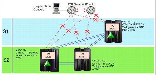
Figure A-10 Migration from an STP-only CTN to a Mixed CTN: start scenario
We assume that all operating z/OS images that require multisystem synchronization already have the STP-related maintenance applied.
The objectives for the migration back to a Mixed CTN are:
•To have all servers in the timing network end up with a CTN ID = [ITSOPOK] - [31].
•Both the Preferred and the Backup Time Server (CEC2 and CEC1, in this example) are established as stratum 1, stepping to the Sysplex Timers.
•CEC3 as stratum 2 is in STP timing mode, synchronized to a stratum 1 server.
Figure A-11 illustrates the target configuration.
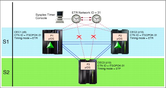
Figure A-11 Migration from an STP-only CTN to a Mixed CTN: end scenario
Preparation
If the Sysplex Timers shown in Figure A-10 on page 180 have not been changed since the migration to STP-only CTN and all ETR cabling is still intact, there is no special preparation.
If the Sysplex Timer configuration has been changed, review the following preparation steps and perform those that are applicable:
1. Verify that an operational Sysplex Timer console is attached to the Sysplex Timers. A Sysplex Timer console is required for all timing-related functions in a Mixed CTN. This console is used for all timing-related functions, such as initializing time, scheduling daylight saving time, adjusting time, and so on.
2. Ensure that all requisite Licensed Internal Code (LIC) has been applied to the Sysplex Timers to support a Mixed CTN configuration.
3. Ensure that the Sysplex Timer ports attached to the Preferred and Backup Time Servers are online and transmitting ETR data.
For high availability, we recommende a minimum of two stratum 1 servers stepping to the Sysplex Timers in an expanded availability configuration.
All z/OS images running in the STP-only CTN have the STP-related maintenance already applied. The Mixed CTN has no additional requirements.
Installation
If the Sysplex Timer configuration has not been changed, there are no special installation tasks. If the Sysplex Timer is a new configuration, refer to the following publications, supplied with the Sysplex Timer, for detailed instructions:
•Planning for the 9037 Model 2 Sysplex Timer, SA22-7233
•Using the 9037 Model 2 Sysplex Timer, SA22-7230
Activation
After the preparation and installation steps are completed, the activation steps can be initiated. All actions are now performed from the Hardware Management Console using the System (Sysplex) Time task.
When properly planned and executed, all operations are concurrent to server operations and nondisruptive to the z/OS images.
Change the CTN ID
A change to the CTN ID can be either GLOBAL or LOCAL. The migration from STP-only to Mixed CTN is initiated via a GLOBAL change to the CTN ID. A GLOBAL change applies to all servers in the CTN. It is initiated from the Network Configuration panel. This can only be done from the Current Time Server or the request is rejected.
A valid ETR network ID (31, in this case) is entered on the Network Configuration panel on the Current Time Server. CEC2 is the Current Time Server in this example.
The action initiates the migration back to a Mixed CTN. As part of the migration, the CTS first steers the CST until it is synchronized with the Sysplex Timer time.
It is most likely that the Sysplex Timer time is out of synch with Coordinated Server Time. An estimated completion time message is displayed, indicating how long it will take for the migration to complete. The amount of time depends on how close the Sysplex Timer time is to the CST. If the time estimated to complete the migration is acceptable, then respond to the message accordingly. Otherwise, indicate that the migration should not proceed. If accepted, the Current Time Server enables the ETR ports for the Preferred and Backup Time Servers if previously assigned (CEC2 and CEC1, in this example). The Coordinated Server Time will start to steer back to the time at the Sysplex Timer. During the migration, any task that involves changing the configuration is not allowed. Migration is only completed when the steering is complete.
|
Note: To minimize the migration duration, a good practice is to synchronize the Sysplex Timers to the same external time source used by the CTN prior to starting the migration.
|
All other servers leave the ETR ports disabled. Other servers in the timing network remain in STP timing mode, receiving their timing signals from the stratum 1 servers.
Figure A-11 on page 181 shows the final configuration.
Enable ETR ports for additional servers
Both the Preferred and Backup Time Server automatically have their ETR ports enabled, and switch from STP to ETR timing mode. Other servers in the CTN remain in STP timing mode.
In our example, CEC3 can have its ETR ports enabled manually to transition to ETR timing mode. The change is made from the ETR Configuration panel and is local to the server.
Migration from an ETR network to an STP-only CTN
A migration from an ETR Timing Network to an STP-only CTN is not possible in one step. The existing ETR network must first be migrated to a Mixed CTN, and then the Mixed CTN must be migrated to an STP-only CTN. However, the two steps can be combined such that they appear as a single migration.
|
Note: Keep the sysplex timer and the STP-only CTN in sync until you are sure that no migration back from the STP-only CTN to a mixed CTN or ETR network must occur. This can be accomplished by synchronizing both the ETR and the CTN to the same external time source. Before the reverse migration can successfully complete the ETR and CTN must have the same time. Otherwise, adjustment steering occurs, which may take several days to complete.
|
Because the target configuration is an STP-only CTN, your planning should include all of the requirements for an STP-only CTN, as described here. All servers in the final configuration must be STP-capable. All z/OS images that require synchronization must have the STP maintenance applied.
This scenario assumes that:
•All servers and CFs that are to participate in the CTN are STP-capable and are already synchronized in an ETR network.
There may be other non-STP-capable servers present but they cannot be considered for the migration to an STP-only CTN. They remain either synchronized to a different ETR network or unsynchronized.
•Coupling link connectivity is already in place for STP messaging and satisfies redundancy requirements for STP.
•The HMC on the operations LAN has access to all servers in the intended STP-only CTN. All the servers in this example are located within a single data center.
During a migration from a Mixed to STP-only CTN, the assigned Current Time Server inherits the time definitions from the ETR. No time initialization is required. However, the time zone offset must be configured to complete the migration.
Figure A-12 shows an example. STP-capable servers CEC1, CEC2, and CEC3 are configured in an ETR network, synchronized by the Sysplex Timers. Logical partitions P1, P2, and P3 are z/OS system images in a Parallel Sysplex, using internal coupling facilities (ICFs) on servers CEC1 and CEC2. All the servers in this example are located within a single data center.
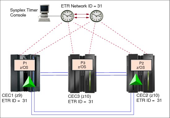
Figure A-12 Migration from an ETR network to an STP-only CTN: start scenario
When the migration to STP-only CTN is complete:
•CEC1, CEC2, and CEC3 are configured in an STP-only CTN. The CTN ID contains only an STP network ID and no ETR network ID. A Preferred Time Server, a Backup Time Server, and an Arbiter are defined.
•CEC1, CEC2, and CEC3 has no active connection to the Sysplex Timer. ETR ports on all servers are disabled. However, the ETR links should remain in place for a certain period of time to allow for a backout plan. Depending on individual change management constraints, the ETR links can be disconnected once a migration back to a Mixed CTN is no longer being considered.
|
Note: Disable the ETR ports to the CECs in STP timing mode on the Sysplex Timer after a successful migration. Otherwise, during a power-on reset (POR) the CEC initially adjusts its internal clock using the timing signals from the sysplex timer and will later adjust it to the CTN time. Depending on the discrepancy between the two clock sources, this adjustment might take some time.
Remember to enable the ports on the sysplex timer again when you plan a reverse migration.
|
Preparation
There are preparation tasks associated with hardware and software components. It is important to complete all hardware and z/OS preparation tasks for the intended STP-only CTN prior to performing either the hardware or z/OS installation tasks.
Prepare the hardware for migration by configuring your system as follows:
•At least one HMC in an STP-only CTN must be configured with connectivity to each server in the CTN. The HMCs must be running the HMC Application V2.9.2 or later.
In an STP-only CTN, the HMC is used to modify the time zone, daylight saving time, and possibly leap second offsets. If using an external time source, an HMC must be chosen that has the ability to dial-out via an analog phone line.
•Hardware MCLs must be installed on CEC1, CEC2, CEC3, and the sysplex timer.
•If using an external time source, dial-out or NTP, access to the ETS must be configured and tested. Refer to “External time source” on page 46.
•The target CTN in this example has three servers, so plan to assign roles. A Preferred Time Server, Backup Time Server, and Arbiter are selected. Although optional, the Arbiter provides additional means for the Backup Time Server to determine whether it should take over in the event of unplanned outages.
Installation
For installation:
•Install the STP feature on CEC1, CEC2, and CEC3. Installation of the STP feature is concurrent. After installation of the STP feature, the server can be configured for STP.
– The System (Sysplex) Time task is available on the SE and HMC to configure a server to use STP. Various functions, such as initialization of the CTN ID, can now be performed.
– Coupling facility partitions automatically recognize the new functions.
•Install the STP-related maintenance on all z/OS images that require time synchronization. In the example, the STP-related maintenance must be installed on all images (P1, P2, and P3).
A re-IPL of the z/OS images is required to recognize the newly installed STP feature and for the maintenance to take effect.
Activation
After you complete the preparation and installation tasks, you can initiate the CTN configuration and activation steps.
When properly planned and executed, all operations from here on are concurrent to server operations and nondisruptive to the z/OS images. All actions are initiated from the HMC using the System (Sysplex) Timer task.
Assign a CTN ID
Within the Network Configuration panel, do not change the ETR network ID already assigned to the ETR network. Only the STP network ID portion of the CTN ID should be specified.
In this example, the value is entered for each server so that the same CTN ID is assigned to CEC1, CEC2, and CEC3. When done, CEC1, CEC2, and CEC3 are all running in ETR timing mode and are defined in a common Mixed CTN with CTN ID = [ITSOPOK] - [31].
Assign the server roles
This step transitions all servers to STP timing mode. It migrates the network to an STP-only CTN. This is done from the Network Configuration tab. However, start by verifying the STP messaging capability and lnks redundancy from the STP STATUS tab.
In this example, CEC2 is assigned the role of Preferred Time Server (PTS). It is also the CTS. The Backup Time Server and Arbiter roles are also defined at this point. In this example CEC1 is assigned as the BTS and CEC3 as the Arbiter. The change is initiated from the Network Configuration tab on CEC1 that is to become the Current Time Server.
|
Important: No manual action is needed to update the CTN ID. The change is made by STP when the Current Time Server is established. The operation must be initiated from the server that will become the Current Time Server as a result of the operation.
|
When the role assignment is done and Apply is clicked, the following actions are taken:
•CEC2 becomes the Current Time Server, stratum 1, and broadcasts its role to the other servers in the network.
•The ETR ports on all the servers in the Mixed CTN are disabled.
•The ETR network ID is removed from the CTN ID for all servers in the CTN. The resulting CTN ID in this example is [ITSOPOK] - [ ].
The new CTN ID is broadcast to all other STP-configured servers in the CTN.
Figure A-13 shows the resulting configuration.

Figure A-13 Migration from an ETR network to an STP-only CTN: end scenario
|
Note: Disable the ETR ports to the CECs in STP timing mode on the Sysplex Timer after a successful migration. Otherwise, during a POR the CEC initially adjusts its internal clock using the timing signals from the sysplex timer and later adjusts it to the CTN time. Depending on the discrepancy, this adjustment might take some time.
Remember to enable the ports on the sysplex timer again when you plan a reverse migration.
|
Installation of a new STP-only CTN
Because the target configuration is an STP-only CTN, your planning should include all the requirements for an STP-only CTN. This scenario assumes that:
•All servers and CFs that are to participate in the CTN are STP capable.
There may be non-STP-capable servers present, but they are not considered for the installation of an STP-only CTN. They can only remain unsynchronized.
•There are no coupling facilities and no coupling facility links.
•The HMC on the operations LAN has access to all servers. All the servers in this example are located within a single data center.
•There are no Sysplex Timers in this configuration. Therefore, there is no need for migration.
Figure A-14 shows an example of the configuration. The example assumes that there is no timing network installed and that the servers are not yet time synchronized. All the servers in this example are located within a single data center.

Figure A-14 Installation of a new STP-only CTN: start scenario
When the initialization of the STP-only CTN is complete, the objective is to have CEC1, CEC2, and CEC3 configured as members of an STP-only CTN. Each server is assigned a specific role in the CTN (Preferred Time Server, Backup Time Server, or Arbiter).
Figure A-15 illustrates the target configuration.
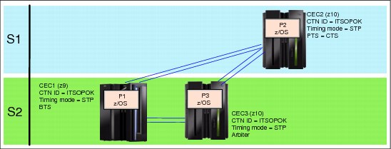
Figure A-15 Installation of a new STP-only CTN: end scenario
Preparation
Prepare the hardware for migration by configuring your environment as follows:
•Ensure availability of an STP-capable HMC. The HMCs must be running the HMC Application V2.9.2 or later. The HMC is used to establish the time zone, daylight saving time, and possibly leap second offsets. If using dial-out ETS, at least one HMC must be chosen that has the ability to dial out via an analog phone line.
•Install hardware MCLs to support STP on the STP-capable servers. In this example, this would be CEC1, CEC2, and CEC3.
•If using an external time source, dial-out or NTP, access to the ETS must be configured and tested. Refer to 2.3, “External time source” on page 46.
•Assign roles
CEC2 in this example is selected as the Preferred Time Server (stratum 1) and is assigned as the Current Time Server.
CEC1 is synchronized to CEC2. Thus, it is a Stratum 2. It is assigned the role of Backup Time Server.
CEC3 is also a stratum 2 synchronized to CEC2. The CEC3 is the Arbiter.
•Order coupling link features on each STP capable server. In this example, we want to add redundant coupling links running between all STP-capable servers (CEC1, CEC2, and CEC3). Because there are no coupling facilities in this example, redundant timing-only links must be defined.
z/OS preparation
To perform z/OS preparation apply STP-related maintenance. This is necessary because servers will be in STP timing mode and time synchronization will be used. A re-IPL of the images is required after installation of the maintenance.
STP feature installation
This task requires the installation of the STP feature on the STP-capable servers. In the example, these are CEC1, CEC2, and CEC3. Three STP features are required.
Installation of the MCL is concurrent. After installation of the STP feature, the servers can be configured for STP.
•STP panels are available on the SE and HMC. Various functions such as initialization of the CTN ID can now be performed.
•z/OS system images must be IPLed.
Activation
After the preparation and installation tasks are completed, the CTN can be defined and activated. When properly planned and executed, all operations are concurrent to server operations and nondisruptive to the z/OS images. The activation steps are:
1. Assign a CTN ID to each server.
2. Initialize the time, including offsets.
3. Assign the Current Time Server.
Assign a CTN ID
Each server must be assigned the same CTN ID. Because this is an STP-only CTN and there is no Sysplex Timer synchronization, there is no ETR network ID present. Only the STP network ID portion of the CTN ID is defined.
The task must be performed for each server in the network from the STP Configuration tab, one server at a time. After all of the servers intended to be configured in the STP-only CTN are assigned the same CTN ID, the System (Sysplex) Time task is available on the SE and HMC.
Initialize the time
Because there is no pre-existing ETR network, there is no inheritance of existing time parameters such as time, time zone offsets, or leap seconds. The information must be defined from the server that will be assigned the Current Time Server, CEC2 in this example.
Specific server in an STP-only CTN
If the STP-only CTN to be activated is a single-server CTN the consideration should be taken to also limit the CTN to a one-server CTN. This is to avoid an automatic CTN deconfiguration during power-on reset or power off/on. This can be achieved by selecting the Only allow the server(s) specified above to be in the CTN option. See 3.4.2, “Single-server or dual-server auto resume after power-on reset” on page 125, for details. The same applies for a two-server CTN.
Assign the Current Time Server
Up to this point, the servers are still unsynchronized (stratum 0) because no time source has been assigned yet.
In this example, CEC2 is to be the stratum 1. CEC2 is assigned the roles of the Preferred Time Server and the Current Time Server. Thus, CEC2 must be the server that assigns the roles. CEC2 can also be used to assign the roles of the Backup Time Server and the Arbiter. These roles can be applied one at a time if desired, or globally. If the Current Time Server role is to change later, the change must be driven by the server that will become the Current Time Server.
In this example, CEC1 is the Backup Timer Server and CEC3 is the Arbiter. The roles are assigned via the System (Sysplex) Time panels.
The operation initializes an STP-only CTN. The change is initiated from CEC2, which becomes the Current Time Server and broadcasts its role to the other servers in the CTN.
Figure A-15 on page 187 shows the resulting STP-only CTN.
Installation of a single-server STP-only CTN
This section describes the migration process for a single-server environment with no existing time synchronization network.
The migration process is concurrent to server operations but disruptive to the z/OS images.
This scenario assumes that:
•The server is STP-capable.
•The HMC on the operations LAN has access to the server.
•The server is not yet time synchronized.
Figure A-14 on page 187 illustrates an example of the configuration.
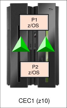
Figure A-16 Installation of a new STP-only CTN: start scenario
When the initialization of the STP-only CTN is complete, the objective is to have CEC1 configured as an STP-only CTN. Since it is the only server in the CTN, CEC1 is assigned the roles of Preferred Time Server and Current Time Server.
Preparation
Prepare the hardware for migration by configuring your environment as follows:
•Ensure availability of an STP-capable HMC. The HMCs must be running HMC Application V2.9.2 or later. The HMC is used to establish the time zone, daylight saving time, and possibly leap second offsets. If using dial-out ETS, at least one HMC must be chosen that has the ability to dial out via an analog phone line.
•Install hardware MCLs to support STP on the STP-capable server, CEC1.
•If using an external time source, dial-out or NTP, access to the ETS must be configured and tested. Refer to 2.3, “External time source” on page 46.
•Assign timing roles. In this example, CEC1 is selected as the Preferred Time Server (stratum 1) and is assigned as the Current Time Server.
z/OS preparation
To perform z/OS preparation apply STP-related maintenance. This is necessary because the server is in STP timing mode and time synchronization is used. A re-IPL of the images is required after installation of the maintenance.
STP feature installation
This task requires the installation of the STP feature on the STP-capable server, CEC1.
Installation of the MCL is concurrent. After installation of the STP feature, the server can be configured for STP. STP panels are available on the SE and HMC. Various functions such as initialization of the CTN ID can now be performed. z/OS system images must be IPLed.
Activation
After the preparation and installation tasks are completed, the CTN can be defined and activated. When properly planned and executed, all operations are concurrent to server operations and nondisruptive to the z/OS images. The activation steps are:
1. Assign a CTN ID to each server.
2. Initialize the time, including offsets.
3. Assign the Current Time Server.
Assign a CTN ID
Because this is an STP-only CTN and there is no Sysplex Timer synchronization, there is no ETR network ID present. Only the STP network ID portion of the CTN ID is defined.
After the server has the CTN ID assigned, the System (Sysplex) Time task is available on the SE and HMC.
Initialize the time
Because there is no pre-existing ETR network, there is no inheritance of existing time parameters such as time, time zone offsets, or leap seconds. The information must be defined from the server that will be assigned the Current Time Server (CEC1 in this example). See the “Configuring an STP-only CTN” section in the Server Time Protocol Implementation Guide, SG24-7281, for details.
Specific server in an STP-only CTN
Since the STP-only CTN to be activated is a single-server CTN, the option should be exercised to limit the CTN to a one-server CTN. This is to avoid an automatic CTN deconfiguration during power-on reset or power off/on. This can be achieved by selecting the Only allow the server(s) specified above to be in the CTN option. See 3.4.2, “Single-server or dual-server auto resume after power-on reset” on page 125, for details.
Assign the Current Time Server
Up to this point, the server is still unsynchronized (stratum 0) because no time source has been assigned yet.
In this example, CEC1 is to be the stratum 1 and is assigned the roles of the Preferred Time Server and the Current Time Server. The roles are assigned via the System (Sysplex) Time panels. The operation initializes an STP-only CTN.
Figure A-15 on page 187 shows the resulting STP-only CTN.

Figure A-17 Installation of a new STP-only CTN: end scenario
Enhancing a single-site ETR network to a Mixed CTN across two sites
This scenario provides an example of a migration from an ETR network to a Mixed CTN within two physical data centers. This scenario has the following assumptions:
•Two sites:
– Site 1 looks similar to the example in , “Migration from an ETR network to a Mixed CTN” on page 170.
– Site 2 has two servers, with no timing network and z/OS images at z/OS V1.11 levels.
•At least two of the servers in the ETR network that are being considered for the migration must be STP-capable.
•z/OS images that require time synchronization, such as those in a Parallel Sysplex, are at z/OS V1.11 levels.
The planning considerations associated with the migration are a combination of the considerations previously discussed in this chapter, with the added complexity of a two-site situation.
Figure A-18 shows an example of such as configuration. This example assumes that all servers at site 1 are already time synchronized using an Expanded Availability Sysplex Timer configuration, with ETR network ID=31. Logical partitions P1, P2, and P3 are three z/OS images participating in a Parallel Sysplex.

Figure A-18 Enhancing a single-site ETR network to a Mixed CTN across two sites: start scenario
The images are connected to the two CFs with sufficient links to avoid a single point of failure.
Site 2 servers are not attached to the Sysplex Timers in site 1. They have coupling link connections to two stratum 1 servers at site 1 to become part of the CTN.
The target configuration is a Mixed CTN. This also implies that the Sysplex Timer must remain as a part of the timing configuration.
When the migration to the Mixed CTN is complete, the objective is to have:
•At site 1, CEC1, CEC2, and CEC3 configured in a Mixed CTN. CEC3 is synchronized to the CEC1 or CEC2 using STP and is no longer directly synchronized to the Sysplex Timer.
•At site 2, CEC4 and CEC5 are configured for STP as members of the same Mixed CTN and are connected to site 1 using new Dense Wave Division Multiplexors (WDM) for coupling link and timing-only link connectivity.
•For redundancy, at least two STP-configured servers remain connected to the Sysplex Timer. They are CEC1 and CEC2 at site 1.
•z/OS images at site 2 are not part of the sysplex configured at site 1, although this would be possible.
Figure A-20 on page 196 illustrates the target configuration.
Preparing to migrate from an ETR network to a Mixed CTN
In this section we discuss preparing to migrate from an ETR network to a Mixed CTN.
Hardware preparation
Prepare your environment by doing the following:
•Ensure availability of an STP-capable HMC. You must plan to either upgrade the existing HMC or purchase a new HMC capable of running the HMC Application V2.10.0 to have visibility to all servers in the CTN. The Support Elements participating in the CTN configuration are CEC4 and CEC5 in site 2, running at console application V2.10.0.
Servers and coupling facilities at both sites should be able to be controlled by a Hardware Management Console. If there are HMCs at both sites, they must be able to access all servers in the Mixed CTN.
In a Mixed CTN, the Sysplex Timer consoles continues to be used for all timing-related functions, such as initializing time, scheduling daylight saving time, adjusting time, and so on. You must keep access to the Sysplex Timer consoles for as long as the Sysplex Timer remains operational in the timing configuration.
•Install hardware MCLs on the STP-capable servers. In the example, this would be CEC1, CEC2, and CEC3 at site 1, and CEC4 and CEC5 at site 2.
•Install LIC 3.0 on the Sysplex Timers.
•Ensure that your DWDM is certified for STP. See:
•High-availability considerations: For high availability, the Mixed CTN should be configured so that every stratum 2 server is attached to at least two stratum 1 servers. You must decide which two servers at site 1 will continue to be synchronized to timing signals provided by the Sysplex Timers in the Mixed CTN.
At site 1, CEC1 and CEC2 continue to step to the Sysplex Timer. CEC3 and both servers at site 2 will be synchronized using STP messages.
We assume that the Mixed CTN configuration is a temporary step towards an STP-only CTN. If the plan is to stay in a Mixed CTN for a long time, it would be advisable to place one Sysplex Timer at site 1 and another at site 2 if fiber distance between sites is less than 40 km. This provides more resiliency and redundancy to the overall configuration.
•Have a plan for timing-only links that might be required. Timing-only links must be configured when a CF does not exist at either end of the coupling link. The CEC3 server at site 1 is the server that will synchronize to either CEC1 or CEC2. Coupling links already exist between CEC1 and CEC2 and can be used to synchronize CEC1 to CEC2 in a future configuration change.
However, there are no coupling links between the CEC1 and CEC3 because only CEC2 has a CF configured. Therefore, it is necessary to order and install coupling links that will be configured as timing-only links between CEC1 and CEC3. The timing-only links can be either the ICB-3, ICB-4, or ISC-3 (peer) links. Figure A-19 on page 195 illustrates the addition of these timing-only links for STP messaging.
CEC4 and CEC5 at site 2 would synchronize to either CEC1 or CEC2 at site 1 using STP timing messages. Coupling links to CEC1 at site 1 must be defined as timing-only links. Coupling links to the CEC2 in site 1 (with a CF) are defined as coupling links.
Figure A-19 illustrates the addition of the coupling links and timing-only links for STP messaging via the DWDMs.
z/OS preparation
Install z/OS maintenance related to STP. In the example discussed here, z/OS images P1, P2, P3, P4, and P5 require the software maintenance. Figure A-19 illustrates the resulting configuration.
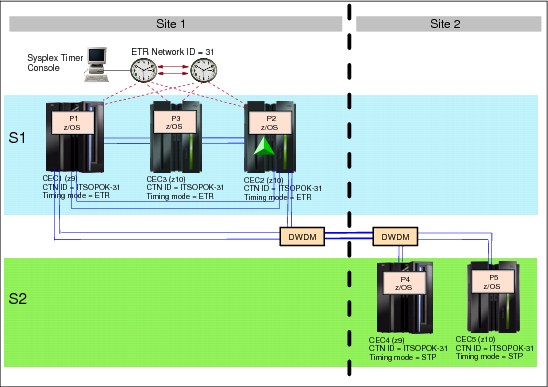
Figure A-19 Enhancing single-site ETR network to Mixed CTN across two sites: synchronized servers
Installation
In this section we discuss installation.
STP feature installation
This task requires the installation of the STP feature on the STP-capable servers. In this example, these are CEC1, CEC2, and CEC3 at site 1, and both servers at site 2.
After installation these servers can now be configured for STP.
•STP panels are available on the Support Element and HMC, and various functions, such as initialization of the CTN ID, can now be performed.
•Coupling facility partitions automatically recognize the new functions.
z/OS images with STP-related maintenance applied, however, require an IPL. In this example, logical partitions P1, P2, P3, P4, and P5 have been upgraded with STP maintenance. An IPL of the images is required to recognize the STP feature.
Activating the configuration for migration
After the preparation and installation tasks are completed, the CTN configuration and activation steps can now be initiated. When properly planned and executed, all operations are concurrent to server operations and nondisruptive to the z/OS images.
Assigning the CTN ID
The Hardware Management Console (HMC) is used to enter the CTN ID. For servers at site 1, the ETR network ID already assigned to the ETR network must not be changed. A new value must be entered for the STP network ID portion of the CTN ID. In this example, a CTN ID = [ITSOPOK] - [31] is assigned to CEC1, CEC2, and CEC3 at site 1.
The same CTN ID must be assigned to the servers at site 2. In this case, both the STP network ID and the ETR network ID must be specified to exactly match the CTN ID at site 1. Assuming that the coupling links are online, CEC4 and CEC5 at site 2 automatically become stratum 2 servers after the CTN ID [ITSOPOK] - [31] is specified. See Figure A-20.

Figure A-20 Enhancing a single-site ETR network to a Mixed CTN across two sites: end scenario
Migrate a server to STP timing mode
The objective is to have CEC3 at site 1 and the two servers at site 2 synchronized to either the CEC1 or CEC2 using STP messages.
You must change the timing mode of CEC3 from ETR timing mode to STP timing mode. The change is made from the ETR Configuration panel of the CEC3 by disabling its ETR ports.
|
Note: The STP messaging capability and links redundancy must first be verified from STP STATUS or CEC3 will go to stratum 0.
|
In this two-site scenario, one Sysplex Timer configuration has been considered. If each site had its own Sysplex Timer configuration, it would have made a nondisruptive migration more challenging, if not impossible. A method has been developed to merge two Sysplex Timer networks, but this procedure usually requires a sysplex outage. Therefore, the scenario that is provided seems to be a more likely approach.
..................Content has been hidden....................
You can't read the all page of ebook, please click here login for view all page.