


Planning hardware and software
This chapter discusses the following planning concepts and considerations:
•Planning for z/VM®
2.1 Planning hardware
STP is a server-wide facility that is implemented in the LIC of the zEC12, z196, z114, z10 EC, z10 BC, z9 EC, and z9 BC servers. This section discusses the following planning topics:
•Installing the Hardware Management Console (HMC) required to support STP. Support Element (SE) planning considerations are also covered.
•Installing the Licensed Internal Code (LIC) on the appropriate servers in the configuration to render them STP capable.
•Installing Feature Code 1021 on STP-capable servers and CFs to render them STP enabled.
2.1.1 Servers
An STP-capable server is a server that has the correct STP feature code installed. Only STP-capable servers can be STP enabled. LIC requirements to make servers STP capable and STP enabled are described later in this chapter. The following servers can be made STP capable:
•IBM zEnterprise EC12
•IBM zEnterprise z196
•IBM zEnterprise z114
•IBM System z10 Enterprise Class (z10 EC)
•IBM System z10 Business Class (z10 BC)
•IBM System z9 Enterprise Class (z9 EC)
•IBM System z9 Business Class (z9 BC)
|
Important: A zEC12 cannot be in the same CTN as z9 or previous servers.
|
A Mixed CTN allows servers that do not support STP to be synchronized in the same network with servers that support STP. However, the servers that do not have the STP feature installed do not support connection to Stratum 2 servers. The Sysplex Timer provides the timekeeping information in a Mixed CTN.
|
Note: zEC12 will be the last high-end server to support connections to a Mixed CTN.
|
Servers used as stand-alone coupling facilities can also be made STP capable. The servers that are used as stand-alone coupling facilities that can be made STP capable are the zEC12, z196, z114, z10 EC, z10 BC, z9 EC, and z9 BC. Table 2-1 provides a summary of the servers and the minimum Coupling Facility Control Code (CFCC) level required. Depending on their server, coupling facilities can be configured in an ETR network, a Mixed CTN, or an STP-only CTN.
Table 2-1 Coupling facility requirements
|
Server
|
CFCC level required on the coupling facility1
|
|
z9 EC and z9 BC
|
CFLEVEL 14 and higher
|
|
z10 EC and z10 BC
|
CFLEVEL 15 and higher
|
|
z196 and z144
|
CFLEVEL 17 and higher
|
|
zEC12
|
CFLEVEL 18 and higher
|
1 zEC12 cannot be in the same CTN as z9 or earlier servers.
2.1.2 Hardware Management Console
The HMC provides the user interface to manage either a Mixed CTN or an STP-only CTN.
HMC functionality in a Mixed CTN
In a Mixed CTN, the HMC is used to:
•Initialize or modify the CTN ID and ETR port states.
•Monitor the status of the CTN.
•Monitor the status of the coupling links initialized for STP message exchanges.
HMC functionality in an STP-only CTN
In an STP-only CTN, the HMC is used to:
•Initialize or modify the CTN ID.
•Initialize the time manually or by using an external time source to keep the Coordinated Server Time (CST) synchronized to the time source provided by the external time source (ETS).
•Initialize the time zone offset, daylight saving time offset, and leap second offset.
•Configure the HMC as an NTP server.
•Configure access to an ETS so that the CST can be steered to an external time source:
– To schedule periodic access to a dial-out external time source 1
– To configure the connection from the NTP client on the SE to NTP servers
– To configure the connection from the NTP client on the SE to NTP servers with pulse per second (PPS)
•Assign the roles of Preferred, Backup, and Current Time Servers, as well as Arbiter.
•Adjust time by up to +/- 60 seconds.
•Schedule changes to offsets listed previously. STP can automatically schedule daylight saving time based on the selected time zone.
•Monitor the status of the CTN.
•Monitor the status of the coupling links initialized for STP message exchanges.
Eligible Hardware Management Consoles
At a minimum, management of STP-enabled servers requires HMC application level V2.9.2 with the latest MCL. Some functions are added or removed in newer levels. For example, NTP server function is only available in HMC application level V2.10.1 and later, and HMC application level V2.12.0 and later no longer support modem (no dial-out capability).
The HMC application level must be equal to or higher than the level of Support Element consoles that it manages. For example, if a zEC12 is part of the CTN, HMC application V2.12.0 or later is required. Table 2-2 shows the major STP-related changes and the HMC Application levels that introduce them.
Table 2-2 HMC STP-related changes
|
Change
|
HMC application level
|
Supported servers
|
|
STP support
|
V2.9.2
|
z9 EC, z9BC and previous
|
|
NTP server in the HMC
|
V2.10.1 and V2.10.2
|
z10 EC, z10 BC and previous
|
|
Removed ETR support
|
V2.11.0 and V2.11.1
|
z196, z114 and previous
|
|
HMC NTP authentication
Removed dial-out support
|
V2.12.0
|
zEC12 and previous
|
Previously installed HMCs can be upgraded by requesting your IBM Service Representative to order the appropriate ECA for each server that has one or more HMC features that must be upgraded. zEC12 requires feature code 0091 and HMC Application level V2.12.0.
Setting up the HMC for local and remote operation
Because of the functionality provided by the HMC, it is required that all CPCs that need role assignment in the STP-only CTN be defined objects to any HMC used to manage the CTN. Furthermore, we strongly recommend that all CPCs in the STP-only CTN or Mixed CTN be defined objects to any HMC in order to have the capability for CTN reconfigurations (for instance, within a recovery scenario). Even remote HMCs should define all CPCs in the CTN. See Figure 2-1.

Figure 2-1 Hardware Management Console: local and remote operations
|
Important: CPCs that are not defined objects to the HMC being used to manage the CTN will not appear in the server pull-down list of the network configuration tab, except when they already have a role assigned (PTS, BTS, or Arbiter). If a CTN reconfiguration is required, it will not be possible to assign a role to the undefined servers. For a new role assignment, one HMC needs access to both the CTS and the target server.
|
There are two methods of defining server (CPC) objects to HMCs:
•When the HMC is on the same local LAN as the servers, local HMCs automatically detect the presence of Support Elements and automatically set up all the necessary internal configuration information for communication without additional information from the users.
•When the HMC is on a remote LAN, defining the servers requires manual action.
For details and guidance consult the manual Hardware Management Console Operations Guide, SC28-6919. The guide has an appendix that explains the process of defining servers to remote HMCs. This publication can be found on the IBM ResourceLink website at:
|
Note: In order to define the CPCs to the HMC, the HMC and the SEs must be part of the same HMC domain security.
|
Always use the switches supplied with the IBM servers to connect HMCs to SEs within a site and between sites. Remote HMCs should be connected via the same switches, and then connected from the IBM switch to the network devices. Figure 2-1 depicts an example of a network with multiple HMCs configured for both local and remote operations.
HMC application programming interface (API)
Specific STP-related attributes have been added to the Defined CPC objects starting with HMC Version 2.10.1. The following STP commands were added in order to manage the CTN or to be able to perform automated recovery actions such as reassigning the PTS, BTS, or Arbiter role in case of a server or site failure:
•Swap Current Time Server
•Set STP Configuration
•Change STP-only CTN
•Join STP-only CTN
•Leave STP-only CTN
For object command details refer to Application Programming Interfaces, SB10-7030.
HMC security
Security for remote HMC connectivity is provided by the HMC user logon procedures in the same way that it is for a local HMC. As with a local HMC, all communication between a remote HMC and each SE is encrypted. Certificates for secure communications are provided and can be changed by the user if desired. TCP/IP access to the remote HMC is controlled through its internally managed firewall and is limited to HMC-related functions.
|
Note: HMC Domain Security can be used to isolate servers on a common LAN or to provide additional security. Individual remote users can be configured to have restricted access in the same way that they can be configured on a local HMC.
|
For a complete description of HMC and Support Element connectivity options refer to the server installation manuals:
•zEnterprise EC12 Installation Manual for Physical Planning, GC28-6914
•zEnterprise 196 Installation Manual for Physical Planning, GC28-6897
•zEnterprise 114 Installation Manual for Physical Planning, GC28-6907
•System z10 EC Installation Manual for Physical Planning, GC28-6864
•System z10 BC Installation Manual for Physical Planning, GC28-6875
•System z9 EC Installation Manual for Physical Planning, GC28-6844
•System z9 BC Installation Manual for Physical Planning, GC28-6855
2.1.3 Support Elements
The Support Elements are important components of STP. The SE’s disk storage provides the means for STP to initialize the configuration and timing parameters. STP configuration information is mirrored to the alternate SE in case the primary SE encounters a problem.
The STP ID, ETR ID, and ETR Port States are stored on the SE and preserved through a power-on reset (POR) and power off/on sequence. Server roles configuration (PTS, BTS, Arbiter) does not remain valid across a power-on reset or power off/on sequence of the CTS unless the CTN is configured with the Only allow the server(s) specified above to be in the CTN option selected.
|
Note: Configuration of a CTN that has Only allows the servers specified above to be in the CTN selected is described in detail in 3.4.2, “Single-server or dual-server auto resume after power-on reset” on page 125. This is also known as saving CTN configuration across power-on reset operations.
|
Disruptive actions, such as power-on reset, are only allowed for servers without roles, or for a server in a single-server CTN.
The server roles must be reassigned after:
•The CTS in a single server CTN has been power-on reset or has gone through a power off/on sequence and has not been specified to be the only member of the CTN. Refer to 3.4.2, “Single-server or dual-server auto resume after power-on reset” on page 125.
•The PTS and BTS, if assigned, in a two-server CTN experience a power outage at the same time (for example, a data center power outage) and they have not been specified to be the only members of the CTN. See 3.4.2, “Single-server or dual-server auto resume after power-on reset” on page 125.
•The PTS and BTS, if assigned, in a CTN with more than two servers experience a power outage at the same time (for example, a data center power outage).
•An STP-only CTN is deconfigured intentionally by the user.
In an STP-only CTN dial-out is possible from a HMC with HMC Application level V2.11.1 or previous, to adjust Coordinated Server Time (CST) to a time standard such as UTC. The SE supports automatic retrieval of time from a time service according to a user defined schedule. The dial-out schedule must be set up using the SE’s scheduled operations task. We recommend that manual actions are used to mirror the dial out schedule immediately to the alternate SE. See the appropriate manual for instructions:
•zEnterprise Support Element Operations Guide V2.11.1, SC28-6906
•System z10 Support Element Operations Guide V2.10.2, SC28-6882
•System z9 Support Element Operations Guide V2.9.2, SC28-6860
|
Dial-out support removal: As with HMC version 2.12.0 dial-out support has been removed. This also impacts SE version 2.12.0. See:
•zEnterprise Support Element Operations Guide V2.12.0, SC28-6920
|
By default, Support Element data is mirrored automatically each day or when internal code changes are installed through single-step internal code changes.
When the external time source is configured to use an NTP server, with or without pulse per second, the NTP client code is on the Support Element. Access to the NTP server is automatic and does not have to be scheduled, as described in 2.3, “External time source” on page 46.
2.1.4 EC levels and MCLs
The STP Licensed Internal Code is already installed in zEnterprise servers, while System z10 and System z9 servers can be made STP capable by installing the STP LIC. The LIC can be installed concurrently. The STP LIC requirements are as follows:
•System z9
– The System z9 must be at EC Driver level 67L or higher.
– Prior to installing the STP feature, the Service Support Representative will download and install the latest MCLs available for the driver. Several STP prerequisite MCLs will be installed as a result.
– After the MCLs are installed, the z9 EC or z9 BC become STP-capable servers. STP functions cannot be used until the STP feature is installed.
•System z10
– The System z10 must be at EC Driver level 79D or higher.
– Prior to installing the STP feature, the Service Support Representative will download and install the latest MCLs available for the driver. STP functions cannot be used until the STP feature is installed.
|
Attention: When a CEC is replaced via an MES, the new CEC is at the latest level. In an STP-only CTN the remaining CECs might be back level (MCLs) due to long intervals between update sessions. This can result in an instability in the CTN due to the fact that certain fixes or enhancements could be set only in the new box.
Also, when adding a new CEC to an existing CTN:
•Ensure that the STP feature is installed.
•Install the latest MCLs on the new and the existing CECs.
|
2.1.5 Installing the STP feature
The STP feature (Feature Code 1021) must be ordered for each server on which STP is to be enabled. This is a chargeable feature for each server. Feature code 1021 provides:
•Installation instructions
The IBM Service Support Representative (SSR) performs this part of the installation.
•A required Sysplex Timer EC LIC disk
The Sysplex Timer's Licensed Internal Code (LIC) has been upgraded to support using STP in a Mixed Coordinated Timing Network (Mixed CTN). The required Sysplex Timer LIC must be installed by the IBM SSR prior to a concurrent migration from a Sysplex Timer-based ETR network to a Mixed CTN.
•A required server diskette or CD
This feature should be installed on any server that will be configured in a Mixed CTN or an STP-only CTN.
STP is enabled without disruption to current operations. This is done through the server SE.
2.1.6 z/BX considerations
The zEnterprise servers’ SE incorporate an NTP server for the use of NTP clients running on zBX firmware components. The goal for zEnterprise is to keep the time stamps in logs on the zBX components in reasonable time coordination with SE logs.
NTP time synchronization is provided also to the hypervisors running on the zBX Power, System x®, and DataPower® blades. For more information, see 2.8, “Planning for zBX” on page 74.
2.2 Planning connectivity
This section focuses on hardware connectivity requirements, offering planning information and recommendations.
2.2.1 Planning for coupling links for STP
STP identifies and maintains a list of all data links on the server that are capable of STP message communication. Coupling-peer data links are the only data links considered to be STP-capable data links.
Three types of external coupling links are available to exchange STP messages to keep servers and CFs synchronized:
•InfiniBand (IFB) links
•Integrated Cluster Bus (ICB)
•Inter System Channel (ISC) links
There are significant differences between the three with respect to the speed of the link and the maximum supported distance. From an availability point of view, all types should be considered to be equivalent, with the same considerations and recommendations. ICB links are used when the servers to be connected are within 7 meters (10 meters cable length). IFB links can be used for distances up to 150 meters, whereas IFB LR (long reach) links can be used for unrepeated distances up to 10 km, or 100 km with repeaters. ISC links can be used for unrepeated distances up to 10 km, or 20 km when running at 1 Gbps.
IFB links
IFB links are high-speed external coupling links available on zEC12, z196, z114, z10 and z9 servers. IFB links consist of a Host Channel Adapter (HCA) coupled directly to the processor I/O interface.
The IBM System z10 and zEnterprise servers support a 12x (12 lanes of fiber in each direction) InfiniBand-Double Data Rate (IB-DDR) coupling link designed to support a total link data rate of 6 GBps. Another option is the IFB LR link, which supports a 1x (one lane of fiber in each direction) InfiniBand-Double Data Rate (IB-DDR) or InfiniBand-Single Data Rate coupling link for a distance of up to 10 km and is capable of a data rate of 5 Gbps. More information about planning for configuration of coupling links is available in IBM System z Connectivity Handbook, SG24-5444, and Implementing and Managing InfiniBand Coupling Links on System z, SG24-7539.
A 12x InfiniBand-Single Data Rate (IB-SDR) coupling link is available between System z10 and System z9 servers. This coupling link is designed to support a total link data rate of 3 GBps. Any other IFB link cannot be used with the System z9 servers.
By feature code, InfiniBand coupling links are:
•FC 0167 (HCA1-O) is for the 12x IB-SDR links between z9 and z10 servers only, on z9.
•FC 0163 (HCA2-O) is for the 12x IB-DDR/SDR links on z10 and zEnterprise servers.
•FC 0168 (HCA2-O LR) is for the 1x IB-DDR/SDR links on z10 and zEnterprise servers.
•FC 0170 (HCA3-O LR) is for the 1x IB-DDR/SDR links on zEnterprise servers.
•FC 0171 (HCA3-O) is for the 12x IB-DDR/SDR links on zEnterprise servers.
Adapter ID assignment and VCHIDs
An adapter ID (AID) is assigned to every IFB link fanout at installation time. It is unique for the CPC. There is only one AID per fanout, so all ports on the fanout share the same AID. The adapter ID is:
•A number between 00 and 1F on z196, z10 EC, and z9 EC
•A number between 00 and 0B on z114
•A number between 00 and 05 on z10 BC
•A number between 08 and 0F on a z9 BC
In the I/O configuration program (IOCP or HCD), the AID and port number are used to connect the assigned CHPID to the physical location of the fanout.
A physical channel identifier (PCHID) normally has a one-to-one relationship between the identifier and a physical location in the machine, however a PCHID in the range from 0700 to 07FF lacks the one-to-one relationship between the identifier and the physical location, either because they do not have a physical card (like Internal Coupling connections (ICPs)), or because they are administered through different identifiers (as for IFB links, with the AIDs). No one-to-one relationship is possible due to the capability to define more than one CHPID for a physical location. Therefore, these are sometimes referred to as Virtual Channel Path Identifiers (VCHIDs).
VCHIDs are assigned automatically by the system and are not defined by you in the IOCDS. A VCHID is also not permanently tied to an AID. Therefore the VCHID assignment can change after a Power-On Reset (POR) if the hardware configuration changed (if a HCA was added or removed, for example). Due to the automatic assignment of the VCHID at every POR, the client or SSR needs to make sure that the correlation for the channel that they intend to manipulate has not changed. The VCHID that is currently associated with a coupling CHPID can be found by issuing an MVS D CF,CFNM=xxxx command for the associated CF.
You can also find the association between a CHPID and a VCHID, which is still referred to as a PCHID by the HMC and the SE, by displaying the VCHID details using the SE. In the HMC you can display the VCHIDs connected between the servers of your CTN, using the STP Status tab, in the System (Sysplex) Timer task. In this tab the VCHIDs will be organized between brackets and parenthesis. The ones that are between parenthesis are assigned to the same physical port in the adapter, and the ones between brackets are assigned to the same physical adapter. For example, in the Figure 2-2 the VCHIDs 704 and 725 are assigned to the same port in the same adapter, while 737 and 738 are assigned to different ports but are in the same physical adapter.

Figure 2-2 Displaying VCHID information (Local STP Link Identifier(s))
IFB cables
IFB links use a multi-pair optical fiber cable. This cable contains 12 pairs of multimode optical fibers, terminated at each end with a Multiple Fiber Push On (MPO) connector. This cable supports the InfiniBand specifications for a 12x or twelve lane connection. The maximum cable length is 150 meters. The cable is not supplied with the IFB feature.
IFB LR links use a one-pair optical fiber cable. This cable contains one pair of single mode optical fibers, terminated at each end with a LC Duplex connector. This cable supports the InfiniBand specifications for a 1x or one lane connection. The maximum cable length is
10 kilometers. The cable is not supplied with the IFB LR feature.
10 kilometers. The cable is not supplied with the IFB LR feature.
IFB3 Protocol
With the introduction of the HCA3-O fanout, it is possible to utilize an improved IFB protocol which is called IFB3. This new protocol provides improved service times for the IFB 12X link. However, certain conditions must be met to utilize it:
•The IFB3 protocol will only be used when both ends of the link are connected to an HCA3-O fanout.
•The IFB3 protocol will only be used if a maximum of four CHPIDs are defined per HCA3-O fanout port for all logical partitions (LPAR) combined.
The IFB link will automatically detect if the given requirements are met and will auto-negotiate the use of the IFB3 protocol. The two ports of an HCA3-O fanout are able to work in different protocol modes. For more information about InfiniBand links refer to IBM System z Connectivity Handbook, SG24-5444, and Implementing and Managing InfiniBand Coupling Links on System z, SG24-7539
ICB links
ICB links are high-speed external coupling links for short-distance connections and are not available for zEnterprise servers. ICB links consist of a 10-meter copper cable (up to seven meters between servers) that connects directly to the Self-Timed Interconnect (STI) I/O interface.
There are two different types of ICBs (ICB-3 and ICB-4). Which one is most appropriate for a given situation depends on the types of servers being connected:
•ICB-3 (FC 0993) supports a link data rate of 1 GBps and is used to connect z9 EC, z9 BC, at a distance of 7 meters.
•ICB-4 (FC 3393) supports a link data rate of 2 GBps and is used to connect z10 EC, z10 BC, z9 EC, and z9 BC servers at a distance of 7 meters.
|
Notes:
•ICB-3 links are not supported on System z10, and will be supported on System z9 through the lifecycle of System z9.
•ICB-4 links are not supported on zEnterprise servers and will be supported on System z10 through the lifecycle of System z10.
|
ICB cables
The total number of servers and ICB features determine the number of ICB cables to be ordered. For example, if two servers with four ICB features are being ordered and enabled, the total number of cables required is two. Proper planning ensures ordering the correct number of cables.
ICB cables are typically delivered with the server. Cables for ICB-3 and ICB-4 are not interchangeable. An ICB-3 cannot use an ICB-4 cable and vice versa. ICB-4 cables from System z9 are not interchangeable with cables for System z10. Installing ICB-4 links with System z10 requires new cables orderable with the System z10.
ICB-3 and ICB-4 cables are orderable as follows:
•ICB-3 Cable (FC 0227)
•ICB-3 Cable for Non Raised Floor (FC 0231)
•ICB-4 Cable (FC 0228)
•ICB-4 Cable for Non Raised Floor (FC 0232)
•ICB-4 Cable for System z10 to System z10 (FC 0230)
•ICB-4 Cable for System z10 to System z9 (FC 0229)
ISC-3 links
ISC-3 links in peer mode support a link data rate of 2 Gbps and are used to connect zEC12, z196, z114, z10, z9, z990, and z890 servers for distances up to 10 km (6.2 miles) without repeaters (WDMs are considered a repeater) using 9-micron single mode fiber optic cables. ISC-3 links are supported exclusively in peer mode, CHPID type CFP.
•FC 0217 - ISC-M (ISC Mother Card)
•FC 0218 - ISC-D (ISC Daughter Cards)
•FC 0219 - ISC-3 Port (2 ports per Daughter card, LIC enabled)
ISC-3 links running at 1 Gbps in Peer Mode (RPQ 8P2197) are supported by STP. This RPQ allows ISC-3 links to be extended to a maximum distance of 20 km without repeaters.
|
Important: zEC12 is the last server to support ISC-3 features, and can only be configured using carry-forward. It also requires an I/O Drawer or I/O Cage, and RPQ 8P2602 requires a 3 or 4 books configuration. ISC-3 links in compatibility mode, and older links prior to ISC-3 cannot be used to exchange STP messages.
|
ISC-3 cables

Figure 2-3 Single Mode Fiber: LC Duplex
Enhanced Book Availability (EBA)
The zEnterprise and System z servers are designed to allow a single book, in a multi-book server, to be concurrently removed from the server and reinstalled during an upgrade or repair action. During the process, it continues to provide connectivity to the server I/O resources using a second path from a different book. With enhanced book availability, and with proper planning to ensure that all resources are still available to run the critical applications in a (N-1) book configuration, planned outages can be avoided.
With Server Time Protocol, it is necessary to ensure that coupling links are not impacted during the removal of a book. This is especially critical where ICB and IFB links are concerned. ICB and IFB links are connected directly to books.
Based on the design of redundant I/O interconnect in I/O cages and drawers that allow for connection through multiple paths, ISC-3 connectivity will not be interrupted. Ensure that all the ICB and IFB links have redundant paths from different books. STI Rebalance feature (FC 2400) might need to be ordered for a System z10 or System z9 after a concurrent book add to provide even distribution of the connections across books.
This planning should be included as part of the initial installation and any follow-on upgrade that modifies the operating environment. The e-config report can be used to determine the number of books, active PUs, memory configuration, and the channel layout.
For more information about Enhanced Book Availability refer to:
•IBM zEnterprise EC12 Technical Guide, SG24-8049
•IBM zEnterprise 196 Technical Guide, SG24-7833
•IBM zEnterprise z114 Technical Guide, SG24-7954
•IBM System z10 Enterprise Class Technical Guide, SG24-7516.
•IBM System z9 Enterprise Class Technical Guide, SG24-7124
Maximum number of links
The maximum number of attached servers supported by any STP server in a CTN is equal to the maximum number of coupling links supported. The number of links that can be installed varies by server type.
|
Important: You must provide at least two coupling links between any two servers that are intended to exchange STP messages for synchronization. This prevents the loss of one link causing the loss of STP communication between the servers.
|
The maximum number of servers that can be attached to a Sysplex Timer is 24. In a high-availability configuration, the Sysplex Timer Expanded Availability (EA) configuration is installed, whereby each server attaches to the two timers in an Expanded Availability configuration.
Table 2-3 Maximum number of coupling links
|
Link type
|
Maximum number of supported links1
|
||||||
|
|
zEC12
|
z196
|
z114
|
z10 EC
|
z10 BC
|
z9 EC
|
z9 BC
|
|
ISC-3
|
482
|
48
|
48
|
48
|
48
|
48
|
48
|
|
ICB-3
|
n/a
|
n/a
|
n/a
|
n/a
|
n/a
|
16
|
16
|
|
ICB-4
|
n/a
|
n/a
|
n/a
|
16
|
12
|
16
|
163
|
|
HCA1-O (IFB)
|
n/a
|
n/a
|
n/a
|
n/a
|
n/a
|
164
|
12
|
|
HCA2-O (IFB)
|
326
|
167
|
328
|
12
|
n/a
|
n/a
|
|
|
HCA2-O LR (IFB LR)
|
32f
|
12g
|
32h
|
12
|
n/a
|
n/a
|
|
|
HCA3-O (IFB)
|
32e
|
32f
|
16g
|
n/a
|
n/a
|
n/a
|
n/a
|
|
HCA3-O LR (IFB LR)
|
649
|
48i
|
3210
|
n/a
|
n/a
|
n/a
|
n/a
|
1 The maximum number of coupling links combined (ICB-3, ICB-4, IFB, active ISC-3 links, and Internal Coupling) for System z10 and System z9 servers is 64, and for zEnterprise servers is 128.
2 zEC12 supports ISC-3, HCA2-O and HCA2-O LR for carry forward only.
3 A z9BC capacity setting A01 supports a maximum of eight ICB-4s.
4 A z9 EC S08 supports a maximum of 12 IFB links.
5 A zEC12 H20 supports a maximum of 16 HCA2-O, HCA2-O LR or HCA3-O IFB links.
6 A z196 M15 supports a maximum of 16 HCA2-O, HCA2-O LR or HCA3-O IFB links.
7 A z114 M05 supports a maximum of 8 HCA2-O, HCA2-O LR or HCA3-O IFB links.
8 A z10 EC E12 supports a maximum of 16 IFB links.
9 A zEC12 H20 and a z196 M15 support a maximum of 32 HCA3-O LR IFB links each.
10 A z114 M05 supports a maximum of 16 HCA3-O LR IFB links
For System z10 and z9 servers, there is a maximum of 64 coupling link CHPIDs per server (ICs, ICB-4s, active ISC-3 links, and IFBs). For zEnterprise servers this maximum is 128 coupling link CHPIDs per server.
The maximum number of external coupling links combined cannot exceed the values shown in Table 2-4. Internal coupling channels (ICs) are not used by STP.
Table 2-4 Maximum number of external coupling links
|
Machine/Model
|
H66, H89 & HA1
|
H43
|
H20
|
|
zEC12
|
104
|
100
|
72
|
|
Machine/Model
|
M49, M66 & M80
|
M32
|
M15
|
|
z196
|
104
|
100
|
72
|
|
Machine/Model
|
M10
|
M05
|
---
|
|
z114
|
72
|
56
|
---
|
|
Machine/Model
|
EC
|
BC
|
---
|
|
z10
|
64
|
56
|
---
|
Coupling link CHPIDs must be defined in peer mode. They cannot be used for STP when defined in compatibility mode.
2.2.2 Planning for timing-only links
Timing-only links are coupling links that allow two servers to be synchronized using STP messages when a CF does not exist at either end of the coupling link. Refer to 1.5.2, “Coupling link requirements in a non-sysplex configuration” on page 23, for an example of time coordination requirements in a non-sysplex configuration.
HCD has been enhanced to define timing-only links and a new STP control unit. Installation of the HCD/IOCP/HCM support is required to obtain the enhancement.
Hardware Configuration Dialog: timing-only links
Hardware Configuration Dialog (HCD) and Hardware Configuration Manager (HCM) support the definition of timing-only links. The timing-only links bring STP capability into a basic-mode sysplex, or a non-sysplex set of systems that do not currently have coupling links in use the way that a Parallel Sysplex, by definition, would.
A timing-only link is established through the CF Channel Path Connectivity List panel in HCD. This is shown in Figure 2-4. Defining timing-only links is very much like defining other coupling links. IFB links are defined as CIB, ISC-3 links are defined as CFP, and ICB-3 or ICB-4 links are defined as CBP using the normal CF connection dialogs. As with coupling links, timing-only links can be defined as dedicated, reconfigurable, shared, or spanned. Multiple Image Facility (MIF) can be used to share the timing-only link between z/OS images on a server, but not between CF images on a server.
|
Connect to CF Channel Path
Specify the following values.
Source processor ID . . . . . : SCZP301
Source channel subsystem ID . : 3
Source channel path ID . . . . : A0
Source channel path type . . . : CFP
Destination processor ID . . . . . . SCZP201 +
Destination channel subsystem ID . . 0 +
Destination channel path ID . . . . A3 +
Timing-only link . . . . . . . . . . Yes
|
Figure 2-4 HCD: timing-only link definition
The HCD dialog contains an option where the user can specify whether the CF connection is for a timing-only link. The default is no. If the user selects a timing-only link, HCD generates an STP control unit on each side of the connection, and no devices. The last line (see Figure 2-4) to define a timing-only link is added to the dialog window.
|
Note: The addition of timing-only links is fully supported by the Dynamic I/O Reconfiguration process so that they can be added non-disruptively.
|
For a timing-only link, HCD performs the following checks:
•The CHPIDs of a timing-only link must belong to different servers. A timing-only link cannot be looped back into the same server.
•If a CF connection already exists between two servers, HCD does not allow defining a timing-only connection between these servers. Also, if a timing-only link already exists between two servers, HCD will not allow defining a CF connection between these servers. The existing connection type must be broken before the other connection type can be established.
|
Note: CF messages cannot be transferred over timing-only links.
|
Timing-only links are supported between all System z and zEnterprise servers, except between a zEC12 and a z92. The status of these links can be displayed from the STP Status panel within the System (Sysplex) Time task in the HMC workplace. It reflects which links are available and initialized.
Standalone coupling facilities and timing-only links
Dynamic I/O reconfiguration supports the transition from timing-only to standard coupling links. However, a stand-alone coupling facility has no z/OS image to facilitate the initiation of a Dynamic I/O reconfiguration. A power-on reset is necessary to make the change at the coupling facility end of the link.
|
Important: We recommend that a single IODF be used for all servers in the installation.
|
2.2.3 Considerations for multi-site sysplex
In current business and IT environments, two important objectives for survival are systems designed to provide continuous availability and near transparent DR. Systems that are designed to deliver continuous availability combine the characteristics of high availability and near continuous operations to deliver high levels of service—targeted at 24x7. To attain high levels of continuous availability and near-transparent DR, the solution should be based on geographical clusters such as a multi-site sysplex and data mirroring. Geographically Dispersed Parallel Sysplex (GDPS) is an industry-leading solution that provides this capability. For more information about GDPS see:
If a sysplex across two or more sites is configured, it is necessary to synchronize servers in multiple sites. Consequently, you might plan to extend the ISC-3 or IFB links beyond the distance supported without repeaters. IBM supports Wavelength Division Multiplexing (WDM) products qualified by IBM for use in multi-site sysplex solutions such as GDPS.
|
Attention: To transmit timing information, STP can choose any defined coupling link that is online between two zEnterprise or System z servers. If coupling links are configured over WDM equipment, all coupling links must use specific WDM hardware (optical modules1, transponders2, TDM modules3) with interface cards qualified by IBM for STP.
If both coupling facility data and STP timing information must be transmitted between two servers, you cannot select a subset of coupling links to be used only for STP timing information.
|
1 Including, but not limited to optical multiplexers/demultiplexers, optical add-drop modules (OADM), small form-factor pluggable (SFP) transceivers, dispersion compensation modules, optical amplifiers, and so forth
2 Wavelength-converting transponders: converts client layer signal to WDM wavelength
3 Time-Division Multiplexing modules: used to transmit multiple data links over the same WDM channel
The latest list of qualified WDM vendor products and links to corresponding Redpapers™ for each product can be found on the Resource Link® website at:
They are listed under Hardware products for servers on the Library page.
2.3 External time source
If there are specific requirements to provide accurate time relative to an external time standard for data processing applications, then consider using the ETS function.
In a Mixed CTN, the ETS function is provided by the Sysplex Timer. The planning considerations are the same as those for an ETR network.
In an STP-only CTN, the ETS function is provided by the following options:
•The dial-out service on the HMC
•An NTP server
•An NTP server with a pulse per second output option
The Current Time Server (CTS) is the only server that adjusts the Coordinated Server Time (CST) by steering it to the time obtained from an external time source.
|
Note: The HMC application level 2.12.0, required for zEC12, does not support dial-out.
|
2.3.1 Dial-out on the Hardware Management Console
When dial-out3 is configured from the HMC to an available time service, the following three protocols are supported:
•NIST4 Automated Computer Time Service (ACTS)
•IEN5 Telephone Date Code (CTD)
•NRC6 Canadian Time Service
A modem attached to the HMC is required to perform this function. The Coordinated Server Time can be initialized for the STP-only CTN to within +/- 100 ms of the time provided by the configured dial-out time service. Once the Coordinated Server Time has been initialized, a periodic dial-out to the time service, either manually or automatically, is needed in order to maintain the accuracy of the CST.
|
Note: The actual time accuracy, relative to UTC, depends on the accuracy provided by the dial-out time service.
|
Using dial-out to telephone time service consists of two steps:
1. Configure an HMC to dial out to telephone time services. At the External Time Source tab of the Customize Outbound Connectivity task on the HMC, check both the Enable local system as a call-home server and the Allow external time source dialing using the local modem check boxes to enable the configuration of the external time source. Configuration of the ETS should be done on multiple HMCs in order to have an alternate HMC for ETS queries.
2. Add scheduled operations to access the ETS from the Preferred Time Server (PTS) and the Backup Time Server (BTS), if applicable. Scheduled operations are included on the BTS for situations when the BTS becomes the CTS.
The HMC and SE support automatic retrieval of the time from a time service and automatic update of CST on a scheduled basis.
Setting up a schedule to dial out to the time service automatically can be done from the HMC. Select a server as the target object, then select Operational Customization ∅ Customize Scheduled Operations ∅ Options ∅ New ∅ Access external time source. One of the following can be requested:
– A single scheduled operation at a specified date and time
– A recurring scheduled operation that occurs at a specified frequency
Scheduled operations that are to be executed by a server that is not the Current Time Server are ignored. At the scheduled time the SE requests the HMC to dial out to the time service. The HMC sends the difference with the time obtained from the service to the STP facility, which will make gradual adjustments by steering the CST to the time obtained from the external time source.
|
Note: The HMC Application level 2.12.0, required for zEC12, does not support dial-out.
|
2.3.2 NTP server
The use of a Network Time Protocol server as an external time source addresses the requirement of customers who need an accurate time source for the zEnterprise or System z server, or those who need to use an accurate common time reference across heterogeneous platforms. These customers, in most cases, purchase an NTP server that will obtain the time using high-precision time technology, such as GPS signals. Actual time accuracy, relative to UTC, depends on how accurate the NTP server time is with respect to UTC. Proper NTP server selection is more of a business decision than a technical requirement.
|
Note: Like STP, NTP is a hierarchical protocol with servers organized in stratum levels. However, there are significant differences between NTP and STP stratum, so these terms cannot be intermixed.
|
For further information about NTP refer to the RFCs at the following web pages:
•NTPv3: http://www.faqs.org/rfcs/rfc1305.html
For further information about NTP and the NTP Public services project refer to the following websites:
NTP client support on the Support Element
The NTP client on System z and zEnterprise servers can provide accuracy for the Coordinated Server Time by accessing an NTP server. An accuracy of 100 milliseconds to the time provided by the NTP server is possible. Simple Network Time Protocol (SNTP) client support is added to the STP code on the SE to interface with those NTP servers. Access to the NTP server from the CTS is initiated and controlled by the Support Element.
Planning for NTP client and LAN connectivity
The implementation of the SNTP client on the Support Element employs:
•NTP V3 (RFC-1305), NTP V4 (RFC-5905), or SNTP V4 (RFC-4330) on zEC12, z196, z114, System z10, and System z9 at Driver 67L
•IPv4 or IPv6 on zEC12, z196, z114, and System z10
•IPv4 on System z9 at Driver 67L
The NTP server can be either an external time source device available from several timekeeping device manufacturers, a local NTP server, or an NTP server configured on the HMC. The NTP traffic between the SNTP client (running on the Support Element) and the NTP server is not encrypted.
Several manufacturers market NTP servers that contain a 9037 Sysplex Timer connection in addition to NTP outputs. This option allows customers to migrate from an existing ETS connection on the 9037 to an STP-only CTN with NTP, without having to invest in a new NTP server. The solution provides time continuity (to the external time source provided by the unit) throughout the entire STP migration path. This might have value for customers with time accuracy requirements when migrating from an ETR configuration with an external time source to a Mixed CTN, and then to an STP-only CTN with NTP.
NTP server on the HMC
The NTP server configured as the ETS must be attached directly to the SE LAN. The SE LAN is considered in many configurations to be a private (dedicated) LAN and should be kept as isolated as possible. Allowing the NTP client running on the SE to directly communicate to an NTP server that is on the corporate or the external network (Internet) introduces potential security issues (even if the SE LAN is behind a firewall).
|
Note: For security reasons, we do not recommend configuring the SNTP client on the Support Element to directly access NTP servers outside its local area network.
|
The ability to define an NTP server on the HMC addresses potential security concerns because the HMC is normally attached directly to the SE LAN. The NTP server on the HMC can access another NTP server via a separate LAN connection to obtain its time reference (Figure 2-5).
|
Note: The NTP server function on the HMC does not provide a pulse per second output.
|
Figure 2-5 HMC acting as NTP server
HMC NTP broadband authentication support
The possibility to use HMC NTP authentication is added with HMC level 2.12.0. To exploit this option on the SE, configure the HMC with NTP authentication as the NTP server for the SE. The following scenarios describe the situations in which you could exploit this option.
•Authentication support with a proxy
Some configurations use a proxy to access outside the corporate data center. NTP requests are UDP socket packets and cannot pass through the proxy. The proxy must be configured as an NTP server to get to target servers on the web. Authentication can be set up on the proxy to communicate to the target time sources.
Some configurations use a proxy to access outside the corporate data center. NTP requests are UDP socket packets and cannot pass through the proxy. The proxy must be configured as an NTP server to get to target servers on the web. Authentication can be set up on the proxy to communicate to the target time sources.
•Authentication support with a firewall
Some configurations use a firewall. HMC NTP requests can pass through the firewall. When using this configuration, you should use the HMC authentication to ensure un-tampered with time stamps.
Some configurations use a firewall. HMC NTP requests can pass through the firewall. When using this configuration, you should use the HMC authentication to ensure un-tampered with time stamps.
•Symmetric key and autokey authentication
With the symmetric key and autokey authentication, the highest level of NTP security is available. HMC application level 2.12.0 provides panels that accept and generate key information to be configured into the HMC NTP configuration, and offer the possibility to issue NTP commands.
With the symmetric key and autokey authentication, the highest level of NTP security is available. HMC application level 2.12.0 provides panels that accept and generate key information to be configured into the HMC NTP configuration, and offer the possibility to issue NTP commands.
– Symmetric key (NTPv3-NTPv4) authentication
Symmetric key authentication, as described in RFC-1305 (made available in NTPv3), uses the same key for both encryption and decryption. Users exchanging data keep this key to themselves. Messages encrypted with a secret key can only be decrypted with the same secret key. Symmetric does support network address translation (NAT).
Symmetric key authentication, as described in RFC-1305 (made available in NTPv3), uses the same key for both encryption and decryption. Users exchanging data keep this key to themselves. Messages encrypted with a secret key can only be decrypted with the same secret key. Symmetric does support network address translation (NAT).
– Autokey (NTPv4) authentication
Autokey authentication, as described in RFC-5906 (made available in NTPv4), uses public key cryptography. The key generation for the HMC NTP is performed by clicking the “Generate Local Host Key” button on the Autokey Configuration panel. Pressing this button will issue the “ntp-keygen” command to generate the specific key and certificate for this system. Autokey authentication is not available with NAT firewall.
Autokey authentication, as described in RFC-5906 (made available in NTPv4), uses public key cryptography. The key generation for the HMC NTP is performed by clicking the “Generate Local Host Key” button on the Autokey Configuration panel. Pressing this button will issue the “ntp-keygen” command to generate the specific key and certificate for this system. Autokey authentication is not available with NAT firewall.
– NTP commands
NTP command support is also added to display the status of remote NTP servers and the current NTP server (HMC).
NTP command support is also added to display the status of remote NTP servers and the current NTP server (HMC).
Planning for NTP server configuration
There are many possible configuration variations, depending on the type of NTP server equipment used, redundancy and security requirements, and existing LAN topology.
In the examples presented in this document, firewalls are indicated to draw the reader’s attention to the potential network security concerns.
|
Note: Configuration of network components, such as routers or firewall rules, goes beyond the scope of this document. Refer to Hardware Management Console Operations Guide, SC28-6919, and to the Installation Manual for Physical Planning (select the manual specific to your server) for security guidelines and recommendations for the HMC/SE network. For IBM zEnterprise and System z hardware documentation, see:
|
Example: Single NTP server (typically from a timekeeping device manufacturer)
Figure 2-6 on page 51 shows an example that has an NTP server attached directly to the SE LAN. Note that in this case, the NTP server is a single point of failure.

Figure 2-6 zEnterprise and other platforms configured with NTP server
One of the NTP output ports of the NTP server is connected directly to the HMC/SE local area network, allowing the SNTP client on the Support Element to obtain the external time from the NTP server. Other NTP output ports of this NTP server can be connected to other platforms that need the same accurate time reference.
In this example, there is no ETS (NTP server, in this case) redundancy. To provide redundancy, additional NTP servers can be installed and configured, as shown in the following section.
NTP server redundancy
The CTS is the only server that adjusts the CST by steering it to the time obtained from an external time source. To provide ETS redundancy, the user should consider configuring two or more NTP servers.7
Up to two NTP servers can be configured on each server in the STP-only CTN. When two NTP servers are configured, the user is responsible for selecting the preferred NTP server. This NTP server is called the selected NTP server. The other is called the non-selected NTP server. Normally, the SNTP client uses the time information from the selected NTP server to perform the time adjustment. The SNTP client also compares the quality of both NTP servers and informs the user in case either of the following conditions is detected:
•The selected NTP server has a stratum level that is lower in the hierarchy than the non-selected NTP server. (A stratum 1 server is a better choice than a stratum 2.)
•The time obtained from the selected NTP server has less accuracy than the non-selected NTP server.
The following planning considerations should be made to provide NTP server redundancy:
•When two NTP servers are configured on the server that has the PTS/CTS role, STP will automatically access the second NTP server configured on the PTS/CTS if the selected NTP server fails.
•When NTP servers are configured on the server with the BTS role, the following is provided:
– Access to an NTP server when the BTS becomes the CTS as the result of planned or unplanned recovery
– Time adjustments to the STP-only CTN when the PTS/CTS cannot access any of its NTP servers
|
Recommendation: Configure at least one unique NTP server on both the PTS and the BTS. For redundancy, up to two separate NTP servers can be configured for both the Primary Time Server (PTS) and the Backup Time Server (BTS).
|
Example: Using the HMC to provide NTP server redundancy
A second example is illustrated in Figure 2-7. One of the NTP ports of NTP server 1 is connected directly to the HMC/SE local area network, as in the previous example. However, this example also introduces using the HMC as an NTP server to provide NTP server redundancy.
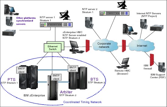
Figure 2-7 zEnterprise and other platforms configured with NTP servers: Example 2
Since the HMC is normally connected to the SE LAN, the capability to configure an NTP server on the HMC should be considered. The HMC can connect using a different network adapter to a remote NTP server located on the corporate intranet, or even on the Internet to access its time reference (NTP server 2 in Figure 2-7). Such a configuration requires UDP port 123 being enabled on the customer firewall to allow NTP traffic between the local NTP server (running on HMC) and remote NTP servers.
Alternatively, a separate NTP server (for example, running on UNIX or Linux) can be configured similar to the HMC (with dual Ethernet adapters) and connected directly to the SE LAN. This provides separation between the HMC/SE LAN and the external networks.
This configuration offers redundancy because the SNTP client on the SE allows configuration of two NTP servers. If the preferred NTP server (NTP Server 1 in this example) cannot be accessed, time adjustments can still be made by accessing the NTP server on the HMC. Refer to Server Time Protocol Recovery Guide, SG24-7380, for a more detailed discussion.
As in the first example, browser access to the HMC might be available using the corporate network through the customer firewall.
Example: NTP server redundancy on PTS and BTS
Figure 2-8 shows a third example. It involves multiple sites with NTP servers accessing remote NTP servers on the corporate network or the Internet. This example is different from the previous ones because the corporate network is always used as an access path to the time source. In addition, even though the example uses multiple sites, this configuration can be used in a single site as well.

Figure 2-8 zEnterprise and other platforms configured with NTP servers: Example 3
This configuration shows that continuous availability of NTP servers can be obtained by configuring a different NTP server in site 1 (on the PTS/CTS) and site 2 (on the BTS). In each site a different HMC is providing the NTP server function. The HMCs in turn can get their time reference from the corporate NTP server 1. The BTS in site 2 accesses the NTP server in site 2 on a periodic basis, calculates time adjustments as required, and propagates them to the PTS in site 1. If the PTS/CTS cannot access the NTP server in site 1, it is able to use the adjustments calculated by the BTS to perform the necessary time adjustment steering for the entire CTN.
This example also requires UDP port 123 to be enabled in the customer firewall for access to NTP servers on the corporate network or on the Internet.
The examples presented illustrate that many variations are possible. The choice of one configuration versus another depends on the security and networking requirements of the enterprise.
For more information about NTP server recovery refer to Server Time Protocol Recovery Guide, SG24-7380.
2.3.3 NTP server with pulse per second
The time accuracy of an STP-only CTN has been improved by adding the capability to configure an NTP server that has a PPS output signal as the ETS device. This type of ETS device is available worldwide from several vendors that provide network timing solutions.
Pulse per second is an electrical signal that very precisely indicates the start of a second. STP has been designed to track to the highly stable, accurate PPS signal from the NTP server and maintain an accuracy of 10 microseconds as measured at the PPS input of the zEnterprise or System z server. A number of variables such as accuracy of the NTP server to its time source (GPS radio signals, for example) and the cable used to connect the PPS signal will determine the ultimate accuracy of STP relative to Coordinated Universal Time (UTC).
In comparison, if STP is configured to use a dial-out time service or an NTP server without pulse per second, it provides only a time accuracy of 100 milliseconds to the ETS device.
Planning for NTP server with PPS
To configure an NTP server with PPS, the NTP output of the NTP server must be connected to the Support Element LAN, and the PPS output of the same NTP server must be connected to the PPS input provided on the External Clock Facility (ECF) card of the zEnterprise or System z server.
The NTP information is provided via the HMC/SE local area network. However, the NTP server propagates its pulse per second signal via a coaxial cable. The signals are carried over a copper cable, which is limited in length. The cable length limitation depends on vendor specifications, and certain vendors might offer a fiber optic cable connection as an option. The cable is connected to a coaxial connector, which resides on the ECF card.
As a minimum, one NTP server with a pulse per second output should be configured at the server that has the Current Time Server role.
NTP server with PPS redundancy
Each zEnterprise or System z server has been equipped with two ECF cards, providing the capability of attaching one or two NTP servers with pulse per second. Attaching a second NTP server with pulse per second gives the redundancy that might be required in certain configurations.
When two NTP servers with PPS are configured, the user is responsible for selecting the preferred NTP server. This NTP server is called the selected NTP server with PPS. The other is called the non-selected NTP server with PPS. Normally, STP uses the time information from the selected NTP server to perform the time adjustment. The SNTP client also compares the quality of the NTP data received from both NTP servers and informs the user if either of the following conditions is detected:
•The selected NTP server with PPS has a stratum level that is lower in the hierarchy than the non-selected NTP server. (A stratum 1 server is a better choice than a stratum 2.)
•The time obtained from the selected NTP server with PPS has less accuracy than the non-selected NTP server.
The following planning considerations should be made to provide NTP servers with PPS redundancy:
•When two NTP servers with PPS are configured on the server that has the PTS/CTS role, STP will automatically access the PPS signal from the non-selected NTP server configured on the PTS/CTS if the PPS signal from the selected NTP server fails. Figure 2-9 is an example of this redundancy.
•When NTP servers with PPS are configured on the server with the BTS role, the following is provided:
– Access to an NTP server with PPS when the BTS becomes the CTS as the result of planned or unplanned recovery
– Time adjustments to the STP-only CTN when the PTS/CTS does not receive PPS signals from all of its configured NTP servers with PPS

Figure 2-9 zEnterprise with NTP pulse per second
|
Recommendation: Configure at least one unique NTP server on both the PTS and the BTS. For redundancy, up to two separate NTP servers can be configured for both the PTS and the BTS.
|
Example: Two NTP servers with PPS configured on PTS/CTS
In this example, two NTP servers with PPS are configured on the PTS/CTS (Figure 2-9). The NTP outputs of both NTP servers are connected to the SE LAN via the Ethernet switch. The PPS output of NTP server 1 is connected to PPS port 0, and the PPS output of NTP server 2 is connected to PPS port 1.
Assume that the PTS/CTS is tracking to the PPS signal received on PPS port 0. If there is a failure associated with this PPS signal, STP will switch to the PPS signal received on PPS port 1 and can continue tracking to an ETS, thus maintaining time accuracy.
Refer to Server Time Protocol Recovery Guide, SG24-7380, for a more detailed recovery discussion.
Example: Different NTP servers with PPS on PTS and BTS
The configuration shown in Figure 2-10 allows continuous availability of ETS by configuring a different NTP server in site 1 (NTP server A on the PTS/CTS) and site 2 (NTP server B on the BTS). The PPS output of each NTP server is connected to PPS port 0 on the respective ECF card.

Figure 2-10 NTP servers with pulse per second on PTS and BTS
During normal operation, the STP-only CTN will track to the PPS signals received on PPS port 0 of the PTS/CTS. Also, the BTS in site 2 calculates time adjustments based on NTP data and PPS signals that it receives from NTP server B, and propagates them to the PTS/CTS in site 1. The data from the BTS is not used for steering until there is a planned or unplanned recovery action as follows:
•If the BTS takes over the role of the CTS due to a recovery action, then the STP-only CTN can still continue to track to PPS signals and NTP data received from NTP server B.
•If there is a failure that results in PPS signals from NTP server A not being received by the PTS/CTS, it is able to use the adjustments calculated by the BTS to perform the necessary time adjustment steering for the entire CTN.
For more information about NTP server with PPS recovery, refer to Server Time Protocol Recovery Guide, SG24-7380.
2.4 Internal Battery Feature (IBF)
In order to plan for improved STP recovery when power has failed for a single server (PTS/CTS) or when there is a site power outage in a multi-site configuration, we recommend that you install the Internal Battery Feature on one or more servers in the CTN. If an Internal Battery Feature is installed on your zEnterprise or System z server, STP now has the capability of receiving notification that customer power has failed and that the IBF is engaged. When STP receives this notification from a server that has the role of the PTS/CTS, STP can automatically reassign the role of the CTS to the BTS, thus automating the recovery action and improving availability.
If the entire CTN is located in a single data center and only has two servers (PTS and BTS), then we recommend installing the IBF on both the PTS and the BTS. This should provide recovery capabilities when the server that is the CTS experiences a power failure. If the CTN in a single data center has three or more servers, we recommend assigning the Arbiter, in which case the IBF does not provide any additional benefit for server power outages.
If the CTN spans two data centers, we recommend installing the IBF on the servers that will be assigned the roles of PTS, BTS, and Arbiter. This should provide recovery capabilities when the site where the CTS is located experiences a power failure.
For a more detailed recovery discussion when the IBF is installed, refer to Server Time Protocol Recovery Guide, SG24-7380.
2.5 Planning z/OS software
When migrating from an ETR network to a Mixed CTN or an STP-only CTN, or when a new STP-only CTN is being planned, there are z/OS considerations that must be planned for. Some key planning considerations are:
•Apply STP-related maintenance to all z/OS systems that need multisystem time synchronization.
•Update SYS1.PARMLIB(CLOCKxx) (optional).
2.5.1 z/OS requirements for STP
z/OS releases V1.7 and later support STP.
All z/OS images, whether participating in an STP-only CTN, a Mixed CTN, an ETR timing network, or in an unsynchronized mode, should be migrated to a supported release. This is particularly important when making a change to the timing network.
z/OS maintenance
Even though all supported releases of z/OS have the function to support STP, additional maintenance might be required. Maintenance being installed on the z/OS system image can be done using the rolling IPL process, which avoids a sysplex-wide outage. See also “Requirement to re-IPL z/OS” on page 59.
In a sysplex configuration, if there is any coupling facility or z/OS image running on an STP-enabled server, STP maintenance is required on all z/OS images in the sysplex before the server is STP-configured.
The STP-related maintenance can be found via the appropriate FIXCAT for your server, for example IBM.Device.Server.zEC12-2827.ServerTimeProtocol contains STP-related maintenance for zEC12. To ensure you have the latest maintenance applied, download the current HOLDDATA from:
After downloading, use the SMP/E RECEIVE HOLDDATA command to receive it to your GLOBAL zone, and then generate a report of missing fixes using the SMP/E commands shown in Example 2-1, replacing targetzone with your z/OS target zone.
Example 2-1 Generating fix report
SET BOUNDARY(GLOBAL).
REPORT MISSINGFIX FIXCAT(IBM.DEVICE.SERVER.*.SERVERTIMEPROTOCOL)
ZONES(targetzone).
The generated report will contain all the fixes that belong to this FIXCAT that have not been applied, and will indicate whether they have been received, as shown in Example 2-2.
Example 2-2 Identifying fixes
MISSING FIXCAT SYSMOD REPORT FOR ZONE targetzone
HOLD MISSING HELD ____RESOLVING SYSMOD_____
FIX CATEGORY FMID CLASS APAR SYSMOD NAME STATUS RECEIVED
_______________ _______ _______ _______ _______ _______ ______ ________
IBM.Device.Server.zEC12-2827.ServerTimeProtocol
HBB7780 AA39334 HBB7780 UA66257 GOOD NO
AA39522 HBB7780 UA66476 GOOD NO
AA39956 HBB7780 UA66079 GOOD YES
Identify the SYSMODs that have not been received, download and receive them, and then apply them using the SMP/E APPLY command by specifying their names, or the FIXCAT as their SOURCEID as shown in Example 2-3, replacing the targetzone with your z/OS target zone and removing the CHECK keyword after verifying the HOLD information.
Example 2-3 Applying fixes
SET BDY(targetzone).
APPLY SOURCEID(IBM.DEVICE.SERVER.*.SERVERTIMEPROTOCOL)
BYPASS(HOLDERROR) GROUPEXTEND CHECK.
|
Note: The addition of FIXCAT (fix category) information to Enhanced HOLDDATA and the REPORT MISSINGFIX function introduced in z/OS V1.10 replace the Enhanced PSP Tool function.
|
For information about SMP/E commands syntax or on receiving and applying SYSMODs, refer to SMP/E for z/OS User’s Guide, SA22-7773 or SMP/E for /zOS Reference, SA22-7772.
Requirement to re-IPL z/OS
In any of the following three situations you must re-IPL your z/OS images:
•After installing FC 1021 (STP code)
•After applying z/OS-related maintenance (as required)
•When changing CLOCKxx parameters
2.5.2 CLOCKxx
The z/OS system data set SYS1.PARMLIB contains many members that are used during IPL to determine how the z/OS system should be configured. One member is CLOCKxx, where xx is a 2-character suffix. The CLOCKxx member performs the following functions:
•Allows you to specify the difference between the local time and UTC if you do not want to use the time zone used by ETR or STP
•Provides the means of specifying that z/OS should make use of the Sysplex Timer and its time zone parameters
•Provides the means to specify that z/OS should make use of STP and its time zone parameters
In a multi-system environment, the objective is to share one SYS1.PARMLIB concatenation with as many z/OS images as possible. This simplifies system management by helping to present a single system image to system programmers so that changes must be made in one place rather than in every system image in the sysplex.
For more information about CLOCKxx and the Sysplex Timer see z/OS MVS Setting Up a Sysplex, SA22-7625.
The following CLOCKxx statements have been added in z/OS in support of STP:
•STPMODE
•STPZONE
•TIMEDELTA
Syntax format of CLOCKxx
Example 2-4 Syntax format of CLOCKxx parameters and values
OPERATOR {PROMPT } | {NOPROMPT}
TIMEZONE d.hh.mm.ss
ETRMODE {YES} | {NO }
ETRDELTA nn
ETRZONE {YES} | {NO }
SIMETRID nn
STPMODE {YES} | {NO }
TIMEDELTA nn
STPZONE {YES} | {NO }
IBM supplied default for CLOCKxx
The IBM supplied default PARMLIB member of SYS1.PARMLIB is CLOCK00. If the STP-related maintenance is installed, CLOCK00 contains the parameters shown in Example 2-5.
Example 2-5 Default parameters and values for CLOCKxx
OPERATOR NOPROMPT
TIMEZONE W.00.00.00
ETRMODE YES
ETRZONE YES
STPMODE YES
STPZONE YES
TIMEDELTA 10
Statements and parameters for CLOCKxx
This section identifies the CLOCKxx statements and provides a short description of each statement.
|
Note: When planning to concurrently migrate from an ETR network to a mixed CTN or from a mixed CTN to an STP-only CTN, leave the ETR parameters (ETRMODE, ETRMODE) unchanged and add the STP parameters (STPMODE, STPZONE1), after the ETR parameters. Special attention is required for ETRDELTA and TIMEDELTA. This approach facilitates both forward and reverse migrations. The ETR parameters can be removed after the migration to STP has been completed and the Sysplex Timers have been removed.
|
1 CLOCKxx parameter ETRDELTA should be replaced with TIMEDELTA.
ETRDELTA and TIMEDELTA are aliases for the same CLOCKxx parameter, and only one should be specified. If both are specified, the first one is ignored, and the following message will be generated:
ETRDELTA and TIMEDELTA are aliases for the same CLOCKxx parameter, and only one should be specified. If both are specified, the first one is ignored, and the following message will be generated:
1 IEA385I CLOCKxx ETRDELTA & TIMEDELTA BOTH SPECIFIED. yyyyyyy IGNORED
OPERATOR {PROMPT | NOPROMPT}
This specifies whether the operator is to be prompted to set the TOD clock during system image initialization.
•PROMPT
Specifies that the system image is to prompt the operator during TOD initialization.
•NOPROMPT
Specifies that the system image is not to prompt the operator during TOD initialization unless the TOD clock is not set. This is the default.
Notes
•If ETRMODE YES or STPMODE YES is specified, the system image ignores the OPERATOR parameter.
•OPERATOR PROMPT and SIMETRID are mutually exclusive keywords.
Specify either OPERATOR PROMPT or SIMETRID, but not both. If both are specified, the system image rejects the CLOCKxx member during system image initialization and issues a message to prompt the operator for one of the following:
– A valid CLOCKxx member
– End of Block (EOB) (by pressing the Enter key on the console) to use the defaults
Otherwise, the operator must re-IPL the system image.
ETRMODE {YES | NO}
This specifies whether z/OS should use ETR timing mode. ETRMODE YES must be coded if this system image is a member of a multisystem sysplex in an ETR network or a mixed CTN.
If all z/OS images in the sysplex run in logical partitions or under z/VM on a single physical processor, SIMETRID can be specified instead of ETRMODE YES.
•YES (default)
This specifies that z/OS is to use ETR timing mode, if available. If ETRMODE YES is specified and an operational Sysplex Timer is not available, the operator will be prompted to set the TOD clock during system image initialization.
•NO
This specifies that z/OS is not to use ETR timing mode.
Notes
•If the z/OS system image is running on a server that is in ETR timing mode, and both STPMODE and ETRMODE have been specified as YES, z/OS uses ETRMODE YES.
•If the z/OS system image is running on a server that is in STP timing mode, and both STPMODE and ETRMODE have been specified as YES, z/OS uses STPMODE YES.
•When planning to concurrently migrate from an ETR network to a Mixed CTN, or from a Mixed CTN to an STP-only CTN, it is important that both ETRMODE YES and STPMODE YES are specified prior to the migration for systems that are running on servers that are in ETR timing mode.
ETRDELTA nn
This indicates the greatest difference (in seconds), after IPL, between the system image’s TOD and the Sysplex Timer TOD by which the system image adjusts its TOD, when necessary, to match the Sysplex Timer TOD.
If the difference between the system image’s (CEC) TOD and the Sysplex Timer’s TOD exceeds the ETRDELTA, the result is:
•If the system image is in ETR synchronization mode and is part of a multisystem sysplex, the WTOR message IEA015A is issued.
•If the system image is not part of a multisystem sysplex, processing continues, but the Sysplex Timer is not used for the remainder of that IPL.
If a value of 0 seconds is selected for ETRDELTA, no deviation between the processor TOD clock and the Sysplex Timer clock can be corrected by z/OS, so no TOD adjustment is possible. When a synchronization check is recognized in the ETRDELTA 0 case, one of the two previously described actions will result.
•Value range: 0–99 seconds
•Default: 10 seconds
|
Note: The default of 10 seconds is strongly recommended if you are planning a migration from an ETR network to an STP-only CTN.
Selecting an ETRDELTA value of 10 seconds does not mean that the CEC TOD and the Sysplex Timer TOD can be out of synchronization by as much as 10 seconds. The two TODs are synchronized to a tolerance of a few microseconds and the value of ETRDELTA has no effect on the synchronization tolerance between the processor TOD and the Sysplex Timer TOD.
|
To understand the significance of ETRDELTA and whether you should consider changing the default value of 10 seconds, it is important to first understand what an ETR sync check is. The Sysplex Timer transmits an ETR on-time signal, referred to as the OTE (on time event). It occurs every megamicrosecond - Mμs (1.048576 seconds), and corresponds to the carry-out of bit 32 of the Sysplex Timer TOD. It is initially used as the starting signal for CPC TOD clocks in the clock-setting process, and later to monitor continued synchronization.
The CPC hardware performs this monitoring by comparing the time difference between the received OTE from the Sysplex Timer and the carry signal (bit 32 to bit 31) from the CPC TOD. An ETR sync check condition is generated when this difference is greater than the ETR sync check tolerance.
This tolerance ensures the correct sequence of execution of STCK instructions by different CPCs in the sysplex. The tolerance is CPC-model-dependent, with a typical value of 1 microsecond.
Some of the possible events that could result in a sync check are:
•z/OS is IPLed without the Sysplex Timer, but with ETRMODE=YES. In this case, z/OS uses the current value in the processor TOD clock during IPL. Later, when the Sysplex Timer is attached or powered on, it starts sending data to the attached CPCs. There is a very high probability that a sync check will be detected.
•For certain CPC models, a sync check condition might be detected when a port switch from the active to the alternate port occurs.
•There is a hardware malfunction in either the CPC or Sysplex Timer hardware.
When an ETR sync check condition occurs, the normal recovery action performed by z/OS is to resynchronize the TOD clock to the Sysplex Timer TOD. This is when the value assigned to ETRDELTA has significance. A sync check results in a machine check interrupt, at which time z/OS takes control of all the processor units in the CPC in order to attempt a resynchronization. z/OS compares the difference between the Sysplex Timer time and the TOD clock time, and if the time difference is within the NN value in ETRDELTA, it allows resynchronization and sets the TOD clock with the time value from the Sysplex Timer.
If the resynchronization requires setting the TODs backward in time, z/OS keeps all the processors in the CPC in a disabled spin loop until the new TOD value catches up in time. It is important that no application observes repeated time stamps. In essence, the ETRDELTA value is the maximum time that a spin loop might be observed when z/OS is attempting this resynchronization.
If the resynchronization requires setting the TODs forward in time, z/OS does not have to keep the processors in the CPC in a disabled spin loop and can set the new TOD value immediately.
Should the ETRDELTA default value be changed
A default value of 10 seconds was selected for ETRDELTA because it was felt to be a reasonable amount of time that would not cause system operators or users undue alarm if the system locked up for this duration because it was in a spin loop.
If you select a larger value for ETRDELTA (99 seconds, for example), operators and users are probably going to notice when the CPC is in a spin loop, and unnecessary recovery actions might be taken.
At the other extreme, if you select the smallest value for ETRDELTA, 0 seconds, no deviation between the processor TOD clock and the Sysplex Timer can be corrected by z/OS, so this is not a good idea. There can be small deviations between the two clocks (microseconds) in the normal course of operation and these deviations can be corrected by the software. There is no sense in putting processors in the sysplex in a wait state for deviations that can be corrected and are not significant to the operation of the sysplex. Any value less than 10 seconds will also limit the capability of attaching a Sysplex Timer after z/OS has been IPLed with ETRMODE=YES.
In summary, 10 seconds is a good working value for ETRDELTA and should be used unless there is a specific requirement to make the number smaller or larger. The point to keep in mind is that there is no reason for the processor TOD clock and the Syplex Timer to be out of synchronization by more than a few microseconds.
See also “TIMEDELTA nn” on page 64. TIMEDELTA and ETRDELTA are basically aliases, and are not dependent on whether the server is in ETR or STP timing mode. If both are specified, z/OS will use the second one—whichever one that is—and reject the first one.
Example 2-6 TIMEDELTA and ETRDELTA as aliases
TIMEZONE E.11.00.00
ETRMODE YES
ETRZONE YES
ETRDELTA 10
STPMODE YES
STPZONE YES
TIMEDELTA 10
TIMEDELTA will be used and the following message will be issued:
IEA385I CLOCKxx ETRDELTA & TIMEDELTA BOTH SPECIFIED, ETRDELTA IGNORED
|
Recommendation: We strongly recommend that the value applied to ETRDELTA and TIMEDELTA be left at the default of 10 (seconds). This recommendation is even more important for customers planning a reverse migration. A reverse migration refers to when an STP-only CTN is concurrently migrated to a Mixed-CTN.
|
ETRZONE {YES | NO}
This parameter specifies whether the system image is to get the time zone constant from the Sysplex Timer. The time zone constant specifies the difference between the local time and the UTC.
•YES
This specifies that the system image is to use the Sysplex Timer to set the time zone constant. If ETRZONE YES is specified and an operational Sysplex Timer is not available, the system image uses the time zone constant specified on the TIMEZONE parameter.
•NO
This specifies that the system image is to use the time zone constant specified on the TIMEZONE parameter. Also, it is possible to use the SET CLOCK command to set the local time and date. Specifying NO makes it more difficult to handle Daylight Saving Time.
•Default
– YES when ETRMODE is set to YES
– NO when ETRMODE is set to NO
STPMODE {YES | NO}
This specifies whether z/OS should use STP timing mode.
•YES (default)
This specifies that z/OS is to use STP timing mode if STP is configured.
•NO
This specifies that z/OS is not to use STP timing mode. Either ETR or local z/OS timing mode will be used depending on the value of the ETRMODE keyword and whether the ETR is usable.
|
Notes: If the z/OS system image is running on a server that is in ETR timing mode, and both STPMODE and ETRMODE have been specified as YES, z/OS uses ETRMODE YES.
If the z/OS system image is running on a server that is in STP timing mode, and both STPMODE and ETRMODE have been specified as YES, z/OS uses STPMODE YES.
When planning to concurrently migrate from an ETR network to a Mixed CTN, or from a Mixed CTN to an STP-only CTN, it is important that both ETRMODE YES and STPMODE YES are specified prior to the migration for systems that are running on servers that are in ETR timing mode.
|
TIMEDELTA nn
|
Important: TIMEDELTA and ETRDELTA are basically aliases, and are not dependent on whether the server is in ETR or STP timing mode. If both are specified, z/OS will use the second one—whichever one that is—and reject the first one.
|
This indicates the greatest difference, after IPL, between the system’s TOD and the Coordinated Server Time (the STP stratum 1 server’s time value), by which the system will adjust its TOD, when necessary, to match the stratum 1 server’s TOD.
|
Note: Selecting a TIMEDELTA value of 10 seconds does not mean that the processor TOD and STP CST can be out of synchronization by as much as 10 seconds. The two are synchronized to a tolerance of a few microseconds and the value of TIMEDELTA has no effect on the synchronization tolerance between the processor TOD and CST.
The discussion on “ETRDELTA nn” on page 61 also applies to TIMEDELTA. This will help you understand the significance of TIMEDELTA and whether it should be changed from its default value.
|
If the difference between the system’s TOD and the Coordinated Server Time (CST) exceeds the TIMEDELTA, the result is:
•If the system is in STP synchronization mode and is part of a multisystem sysplex, the WTOR message IEA394A is issued.
•If the system is not part of a multisystem sysplex, processing continues, but STP is not used for the remainder of that IPL.
If a value of 0 seconds is selected for TIMEDELTA, no deviation between the processor TOD clock and the Stratum 1 Server’s TOD can be corrected by z/OS, so no TOD adjustment is possible. When a synch check is recognized in the TIMEDELTA 0 case, one of the two previously described actions will result.
•Value range: 0 to 99 seconds
•Default: 10 seconds
|
Note: The default of 10 seconds is strongly recommended if you are migrating from an ETR network to an STP-only CTN.
|
STPZONE {YES | NO}
This specifies whether the system image is to get the time zone constant from the STP. The time zone constant specifies the difference between the local time and the UTC.
•YES
This specifies that the system image is to use STP to set the time zone constant. If STPZONE YES is specified and STP is not enabled, the system image uses the time zone constant specified on the TIMEZONE parameter.
•NO
This specifies that the system image is to use the time zone constant specified on the TIMEZONE parameter.
•Default
– YES when STPMODE is set to YES
– NO when STPMODE is set to NO
SIMETRID nn
This specifies the simulated Sysplex Timer identifier. SIMETRID allows z/OS images running on the same server, in native mode in logical partitions, or as VM guests, to participate in a multisystem sysplex when no real Sysplex Timer or STP is available. In these environments, the z/OS TOD clocks are synchronized by PR/SM or the z/VM host. If a Sysplex Timer or STP is available when z/OS is not being run as a VM guest, IBM suggests using appropriate statements described previously instead of SIMETRID.
Do not use SIMETRID to coordinate z/OS images running on different servers. Instead, use a real Sysplex Timer together with ETRMODE YES, or run in STP timing mode with STPMODE YES.
SIMETRID is only available when z/OS runs in a logical partition, or under VM.
Each image participating in the same sysplex and using a simulated Sysplex Timer or a simulated STP for time synchronization must specify the same simulated Sysplex Timer identifier (nn).
When the logical TOD clock has been set in a logical partition by an IPL, the logical partition must be reactivated to reset the time again.
|
Note: OPERATOR PROMPT and SIMETRID are mutually exclusive keywords. Specify either OPERATOR PROMPT or SIMETRID, but not both. If both are specified, the system image rejects the CLOCKxx member during initialization and issues a message to prompt the operator for one of the following:
•A valid CLOCKxx member
•EOB (by pressing the Enter key on the console) to use the defaults
|
Otherwise, the operator must re-IPL the system image.
•Value range: a 2-digit hexadecimal number (X'00-1F')
•Default: None
This value is optional. If specified, ETRZONE and ETRMODE are ignored and the time zone constant specified by TIMEZONE is used.
TIMEZONE d.hh.mm.ss
This specifies the difference between the local time and the UTC. If ETRMODE YES and ETRZONE YES are specified and an operational Sysplex Timer is available, the system image ignores the TIMEZONE parameter. Similarly, if STPMODE YES and STPZONE YES are specified and the server is being synchronized using STP messages, the system image ignores the TIMEZONE parameter.
•d
This specifies the direction from UTC.
– Value range: E for East of UTC or W for West of UTC
– Default: W
•hh.mm.ss
This specifies the number of hours (hh) minutes (mm) and seconds (ss) that the local time differs from UTC.
– Value range: The value for hh must be between 00 and 15. The value for mm and ss must be between 00 and 59 (mm.ss values are optional). In addition, the combined hh.mm.ss value must be within the range (00:00:00–15:00:00). This means that a value like 15.59.59 is not valid because it is outside the range, even though the hh portion is between 00 and 15 and the mm and ss portions are between 00 and 59. If the mm portion or ss portion or both are omitted, a default value of 00 is applied to the omitted portion and appears in message IEA598I at IPL time. For example, if CLOCKxx contains TIMEZONE W.15, then at IPL time, message IEA598I indicates:
IEA598I TIME ZONE = W.15.00.00
– Default: 00.00.00
General rules and recommendations
|
Note: The synchronization mode for the server and the synchronization mode for a z/OS image running on the server are usually the same but can be different. If the server is in ETR timing mode, a z/OS image could be running in local, ETR, or SIMETR mode. If the server is in STP timing mode, a z/OS image could be running in local, STP, or SIMETR mode.
|
The following general rules apply to the creation of CLOCKxx:
•The following combinations of parameters are not valid and will be rejected:
– ETRMODE=NO and ETRZONE=YES
– STPMODE=NO and STPZONE=YES
|
Recommendation: STPMODE YES and STPZONE YES are the defaults with z/OS. Letting the STP settings default gives the most configuration flexibility. When both ETRMODE YES and STPMODE YES are in effect, the z/OS synchronization mode is determined by the timing mode of the server.
|
•If both ETRDELTA and TIMEDELTA are specified in the same CLOCKxx member, z/OS will use the second entry, whichever one that is, and flag the first entry as an error. Thus, ETRDELTA should be removed and replaced with TIMEDELTA.
•The CLOCKxx member for a system image that is a member of a multisystem sysplex must contain a specification of ETRMODE YES or STPMODE YES. The system image then uses the Sysplex Timer or STP timing signals to synchronize itself with the other members of the sysplex. The system image uses a synchronized time stamp to provide appropriate sequencing and serialization of events within the sysplex.
2.6 Planning for z/VM
z/VM now exploits the Server Time Protocol (STP) facility to generate time stamps for guest and system DASD write I/O operations, allowing these I/O operations to be synchronized with those of other systems. This support allows data used by z/VM and its guests to be replicated asynchronously over long distances by IBM System Storage® z/OS Global Mirror (formerly known as Extended Remote Copy, or XRC). For example, this allows z/VM to participate in a Geographically Dispersed Parallel Sysplex Metro/z/OS Global Mirror (GDPS/MzGM) environment. This satisfies the statement of direction in the XRC Services announcement dated March 23, 2010.
This baseline STP support is available in z/VM versions 6.2, 6.1 and 5.4, with the last two requiring the PTFs for APARs VM64814 and VM64816, and provides the following functions:
•Synchronizes z/VM TOD clock with STP server at IPL. Before the introduction of baseline STP support it was up to z/VM, under operator control, to change the TOD clock during IPL by the operator prompt for date and time, entering YES to the Change TOD clock {YES|NO} prompt during IPL. With STP support enabled in z/VM, you will not receive any prompts to change the TOD clock; instead, STP is automatically used to initialize the TOD clock with the CST and set the same time zone used by the CTN, displaying this message:
HCP986I "TOD Clock Synchronized via STP."
•Maintains a delta value of TOD changes over the lifetime of the z/VM IPL.
•Supports STP time zone management.
•CPC must be either a member of an STP-only CTN, or a stratum 2 or higher member of a mixed-CTN.
To enable this support, new FEATURES statements for SYSTEM CONFIG were added:
•STP_Timestamping: Timestamps will be added to write channel programs issued to all DASD devices that have the XRC LIC installed.
•STP_TIMEZone/STP_TZ: System time zone will be derived from the STP server.
•XRC_OPTional: System behaves differently when STP is suspended. Instead of deferring all I/O that is to be timestamped until STP sync is restored, it stops timestamping but continues issuing I/O.
•XRC_TEST: Only allowed on 2nd-level z/VM. This will enable STP_Timestamping without STP availability. Manually-specified TOD value is used for timestamping, intended for vendor test support.
For instance, Example 2-7 show the FEATURES section of a SYSTEM CONFIG that has STP_TZ enabled only.
Example 2-7 z/VM SYSTEM CONFIG with STP enabled
/**********************************************************************/
/* Features Statement */
/**********************************************************************/
Features ,
Disable , /* Disable the following features */
Set_Privclass , /* Disallow SET PRIVCLASS command */
Auto_Warm_IPL , /* Prompt at IPL always */
Clear_TDisk , /* Don't clear TDisks at IPL time */
Enable,
STP_TZ , /* timezone from STP on CPC */
Retrieve , /* Retrieve options */
Default 20 , /* Default.... default is 20 */
Maximum 255 , /* Maximum.... default is 255 */
MaxUsers noLimit , /* No limit on number of users */
Passwords_on_Cmds , /* What commands allow passwords? */
Autolog yes , /* ... AUTOLOG does */
Link yes , /* ... LINK does */
Logon yes , /* ... and LOGON does, too */
Vdisk Userlim 144000 blocks /* Maximum vdisk allowed per user */
For more details about the FEATURES statements, refer to CP Planning and Administration, SC24-6178.
2.6.1 STP state flow in z/VM
Depending on what FEATURES statements have been used and on the STP status, you might have different results:
•During IPL:
– If STP_Timestamping, STP_TZ, or both are specified: Perform activation by querying STP and setting the TOD clock to match the STP TOD value.
– If STP_TZ is specified: Set the system timezone to match the STP timezone.
– If either of these fails, STP will enter SUSPENDED state. Otherwise, STP activation completes successfully and STP is considered ACTIVE.
•When STP is ACTIVE:
– If STP_Timestamping is specified: I/O to XRC-capable DASD will be timestamped (when required) and I/O to non-XRC-capable DASD will be unchanged.
•When STP is SUSPENDED:
– If STP_Timestamping is specified and XRC_OPT is not specified: I/O to XRC-capable DASD that must be timestamped will be deferred until STP becomes ACTIVE again, while I/O that does not need to be timestamped and I/O to non-XRC-capable will continue to be issued.
– If STP_Timestamping is specified and XRC_OPT is also specified: I/O to all DASD will be issued without a timestamp until STP becomes ACTIVE again.
Some events in the system might cause STP state changes:
•From ACTIVE to SUSPENDED: Occurs when an STP machine check is received that informs CP that the TOD value must be synchronized.
•From SUSPENDED to ACTIVE: In response to machine check/external interrupts received, CP will attempt to re-synchronize with the STP server. A successful resynch will not change the system TOD value, but will update the delta between the system time and the STP TOD value and will update the system time zone (if STP_TZ is enabled).
•From ACTIVE to ACTIVE: External interrupts might be received that require CP to query STP time zone information (for example, the time zone was changed via the HMC). This does not cause STP to go SUSPENDED, but will cause the system time zone to change.
2.6.2 Updated CP commands
With the baseline STP support to provide accurate XRC timestamping associated with VM guests and host I/O operations, some CP commands were added or updated:
•QUERY STP: This command has been added, and is used to display the Server Time Protocol status. Example 2-8 shows a possible response.
Example 2-8 Query STP information in z/VM
Q STP
Server Time Protocol synchronization activated.
Ready; T=0.01/0.01 17:30:45
•SET TIMEZONE: This command is used to change the system’s time zone ID and time zone offset. It has been updated to display the response shown in Example 2-9 if z/VM is configured to use STP time zone.
Example 2-9 Setting the time zone
SET TIMEZONE EST
HCPTZN987E SET TIMEZONE not valid - STP timezone in use
Ready(00987); T=0.01/0.01 17:28:55
•QUERY TIMEZONES: This command is used to display the list of active and inactive time zone definitions on your system. It has been updated to show the STP time zones when z/VM is configured to use it.
For a full description of possible responses, refer to CP Commands and Utilities Reference, SC24-6175.
2.6.3 z/VM IOCP
If z/VM is used to create IOCP decks for the z/OS logical partitions (not z/OS Guest machines), z/VM can be used to create timing-only links. To define timing-only links, simply define the peer channel (CFP or CBP) with a control unit of UNIT=STP, and no devices. See 2.2.2, “Planning for timing-only links” on page 44.
2.6.4 VM guests
A z/OS sysplex can be established among z/OS images running as guests under z/VM, but the guests still cannot take advantage of STP or the Sysplex Timer. Only their write I/O to an XRC-enabled storage will have the STP timestamps if STP_Timestamping is specified. z/OS sysplex guests use z/VM timer services and must specify SIMETRID in the parmlib CLOCKxx member to synchronize their virtual TOD clocks.
To be able to change the date and time of a guest system running under z/VM, an OPTION TODENABLE statement must be added in the directory entry for the guest virtual machine. Then change the system date and time for the guest system using the procedures of the guest system. TODENABLE must not be specified for guest machines that will be specifying SIMETRID. This support requires that all of the TODs for the system be synchronized, and if TODENABLE is specified, the operator can subsequently change the guest TOD clock.
The three z/OS guest images in Figure 2-11 on page 70 belong to the same sysplex. The guest images must use SIMETRID in their CLOCKxx parmlib members. The TOD clock for a VM guest must not be altered from the value set by LPAR during logical partition activation, either by prior systems IPLed in the partition or z/VM during its initialization.
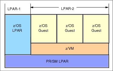
Figure 2-11 A sysplex within a logical partition and VM guests
2.6.5 z/TPF
Server Time Protocol (STP) is supported in z/TPF with APAR PJ36831. PJ36831 was released on PUT 07. Information about STP support in z/TPF can be found in the TPF Information Center:
For more information about z/TPF, refer to the TPF web site at:
Or contact [email protected].
2.7 Special considerations for a single server STP-only CTN
You might want to plan a single-server STP-only CTN because of one or more of the following reasons:
•You have a requirement to coordinate time accuracy across zEnterprise, System z and other platforms of your enterprise. As discussed in “NTP server” on page 48, you can use the ETS option of using an NTP server to accomplish this.
•You have a single server and want to implement a sysplex made up of multiple members. Even though this can be accomplished without using STP and coding SIMETRID nn for the CLOCKxx member of each z/OS image, there are reasons, mentioned in the following paragraphs, that you might want to implement this using STP and coding STPMODE YES in the CLOCKxx member.
You might have both z/OS systems as well as other operating systems that do not support STP running on the single server. In the following text, OS-xyz applies to any operating system that does not support STP, for example z/VSE® or Linux, as well as z/OS systems that do not have STPMODE YES coded in the CLOCKxx member. Even though STP is only supported by z/OS 1.7 and higher, all active LPARs on servers in the STP-only CTN can also benefit from the time accuracy provided by using the ETS function. All LPARs (OS-xyz included) can still maintain time within 100 ms of the External Time Source.
There are a few instances that will cause a larger difference between the CEC time and the ETS time that OS-xyz running on a STP configured server will not be able to handle. These limitations do not apply to images that are at z/OS 1.7 and higher that have STPMODE YES coded in the CLOCKxx member. For details, refer to:
|
Note: The sync check limitation discussed in the referenced document does not apply to a single server CTN, since a stratum 1 server (PTS/CTS) is the source of time and cannot get sync checks.
|
Regardless of the reason you are planning a single server CTN, the hardware and ETS planning will be the same. The software planning in each case might be unique and will determine whether you can do a concurrent implementation or not.
Hardware and ETS planning for single server configuration
Hardware planning includes installing FC 1021 on an STP-capable server. There are no considerations for coupling links as this will be a single-server CTN (no external timing links required).
|
Note: Since you are implementing a single server CTN, your server will be the Primary Time Server and Current Time Server (PTS/CTS). There is no Backup Time Server (BTS) or Arbiter in this configuration. However, all rules for providing ETS redundancy to the PTS/CTS apply here.
It is highly recommended that you save the STP configuration by selecting the Only allow the server(s) specified above to be in the CTN check box in the Network Configuration menu, as shown in Figure 2-12 on page 72.
|

Figure 2-12 Enabling configuration save for single CEC CTN
|
Note: After a power off/on sequence, the TOD value in the Current Time Server is initialized from the TOD values stored in its Support Element. If you have previously configured an external time source, STP code does not perform an initialize time using the ETS, but automatically accesses the configured ETS and starts adjusting the time so as to maintain time accuracy. STP allows time adjustments of up to +/- 60 seconds.
|
2.7.1 Software planning: z/OS currently running in a sysplex
In this section, the assumption is that you have running z/OS systems in a sysplex with SIMETRID coded in the CLOCKxx member prior to configuring an STP-only CTN. You do not have a Sysplex Timer in your configuration attached to the single server.
The main software planning consideration is whether you should continue to run with SIMETRID or whether you should update the CLOCKxx member to use STPMODE YES and STPZONE YES or NO.
Continuing to run with SIMETRID will allow you to configure the CTN concurrently without stopping production. This is because in SIMETRID simulation mode, ETR and STP interrupts and machine checks are not applicable.
For configuring the CTN, refer to “Installation of a new STP-only CTN” on page 187. When the procedure gets you to the initialize time step for a new STP-only CTN, the TOD value can be changed since the z/OS systems are not running in STP or ETR synchronization mode. Appropriate adjustments to the LPAR offset of each z/OS image running with SIMETRID will be made by PR/SM code. There are no WTOR messages posted to the z/OS Console.
As mentioned in 2.5, “Planning z/OS software” on page 57, if a Sysplex Timer or STP is available when z/OS is not being run as a VM guest, IBM recommends using appropriate CLOCKxx statements instead of SIMETRID8 because of the following advantages:
•If you update the CLOCKxx member to use STPMODE YES and STPZONE YES, then Daylight Savings Time (DST) changes can be handled without using manual procedures you might be using today to change the time zone, such as using the SET TIMEZONE command.
•z/OS messages will be posted to the z/OS console when z/OS detects certain conditions with STP such as messages related to ETS. See Appendix B, “Server Time Protocol (STP) messages in z/OS” on page 197.
•If Leap Seconds are important to you, z/OS will recognize them when you specify Leap seconds during the Initialize Time procedure as well as later when Leap seconds are adjusted. See “Leap second offset adjustment” on page 110.
|
Attention: In order to change from z/OS systems running with SIMETRID to STPMODE YES, you must plan to take an outage of the z/OS systems to activate the STP mode. Once the STP-only CTN is configured, you can shut down and re-IPL the z/OS systems using the updated CLOCKxx member.
|
2.7.2 Software planning: z/OS systems currently not in a sysplex
In this section, the assumption is that you have running z/OS systems not in a sysplex prior to configuring an STP-only CTN. You do not have a Sysplex Timer in your configuration attached to the single server.
You might already be running with the defaults in CLOCKxx member, namely STPMODE YES and STPZONE YES. You might be disregarding the messages z/OS posts at IPL time and z/OS has been completing its IPL in local timing mode. Since the z/OS systems are currently running in local mode, you can configure an STP-only CTN without planning to take an outage and shutting down the z/OS systems.
After the STP-only CTN is configured (see “Installation of a new STP-only CTN” on page 187), plan a rolling re-IPL of your z/OS systems using either the defaults in CLOCKxx or updating CLOCKxx to use STPMODE YES and STPZONE YES or NO.
As each z/OS system is re-IPLed, it will now start operating in STP synchronization mode, allowing you to get the advantages stated in the previous section.
|
Note: Once the z/OS systems are running in STPMODE YES, you are now enabled to follow the procedures to set up a sysplex as well.
|
2.7.3 Software planning: z/OS systems currently in a sysplex using ETR
In this section it is assumed that you might have consolidated a multi-server Parallel Sysplex configuration to a single-server configuration and you still have a Sysplex Timer attached to the single server in your configuration. Therefore, we assume that you have ETRMODE YES and ETRZONE as either YES or NO.
The software planning considerations are the same as outlined in 2.5, “Planning z/OS software” on page 57.
You can perform a concurrent migration from ETR to Mixed CTN and from Mixed CTN to STP-only CTN as described in Appendix A, “Migration planning” on page 161.
2.8 Planning for zBX
NTP clients on the BladeCenter® infrastructure, and DataPower appliances, access the SE NTP server every hour to keep time coordinated. The time adjustment is steered to correct time differences.
PowerVM blades
PowerVM® hypervisor accesses the SE NTP server every hour to keep time coordinated. The time adjustment is steered to correct for time differences. During the activation of the hypervisor, a hard adjustment ("jump") is done if the time delta is greater than +-15 seconds, otherwise the time difference is normally adjusted.
Each time a zBX virtual server (VS) on POWER7® is activated, it inherits the system time of its hypervisor (because we delete and re-create the LPAR). From then on, the system clock in the VS runs independently from the hypervisor, and is not corrected as the system clock in the VIOS partition is. All virtual servers on the same hypervisor will have the same skew rate. Since each VS is expected to be activated at different times, each VS might have different accumulated skew values.
|
Important: Once the VS has been activated, if you need to maintain time coordination, you should configure the OS to synchronize its time to an available NTP server.
|
System x blades
The integrated x hypervisor (xHyp) accesses the SE NTP server every hour to keep time coordinated. The time adjustment is steered to correct for time differences. During the activation of the hypervisor, a hard adjustment ("jump") is done if the time delta is greater than +-15 seconds, otherwise the time is normally adjusted.
Each time a zBX virtual server (VS) on System x blade is activated, it inherits the system time of its hypervisor. From then on, the system clock in the virtual server runs independently from the hypervisor, and is not corrected as the system clock is. All virtual servers on the same hypervisor will have the same skew rate. Since each VS is expected to be activated at different times, each VS might have different accumulated skew values.
|
Important: Once the virtual server has been activated, if you require to maintain time coordination with other servers in your environment, you must configure the operating system running on the virtual server to synchronize its time to an available NTP server.
|
2.9 Operating systems with no STP support
There are considerations to be aware of when running an operating system that does not have STP support on an STP-configured server. This is the case for logical partitions running z/VSE or Linux for System z. Consider the following information:
•The logical partition TOD is set to the processor TOD clock at the time that the partition is activated. When using an external time source, either a dial-out from the HMC or an NTP server, logical partitions on servers configured in an STP-only CTN will also benefit from the time adjustment from the ETS function.
An operating system that uses the hardware clock during IPL will obtain the time set in the logical partition TOD clock.
•No STP information will display through the operating system messages. STP hardware messages will still be available on the HMC.
•An STP sync check will not be recognized if one happens and will result in the partition’s logical TOD being offset from the processor TOD clock.
•To reset the logical partition TOD you must deactivate and activate the logical partition, then re-IPL the operating system.
•Leap seconds will not be recognized.
For more detailed information refer to the Techdocs library at:
2.9.1 Linux for System z
The Linux operating system does not support STP or the Sysplex Timer. However, it tolerates their existence. That is, if Linux is running on a server configured with STP with a Sysplex Timer, Linux continues to operate normally and has no awareness of STP or the Sysplex Timer.
The server’s TOD is synchronized to STP or the Sysplex Timer by the LPAR LIC. The logical partition has a logical TOD offset from the processor TOD, which can be set by Linux during IPL. If a synchronization check occurs, the LPAR LIC adjusts the logical TOD offset for each logical partition. To zero out the offset, the logical partition must be deactivated and activated again.
The Linux kernel keeps track of time independently from the hardware clock. During the boot process, Linux sets its own software-managed clock to the same time as the hardware clock. Alternatively, the clock can be set through operator commands. After the boot, the Linux clock runs independently of the hardware clock.
Because Linux manages its own software clock, Linux frequently uses Network Time Protocol to keep its time synchronized to an external source. If the Linux image (logical partition or guest) has a Local Area Network (LAN) connection to an NTP server, Linux can take advantage of it.
2.9.2 z/VSE
The z/VSE operating system does not support STP or the Sysplex Timer. However, if z/VSE is running on an STP-enabled server or with a Sysplex Timer, z/VSE continues to operate normally and has no awareness of STP or the Sysplex Timer.
The server’s TOD is synchronized to STP or the Sysplex Timer by the LPAR LIC. The logical partition has a logical TOD that can be set by z/VSE during IPL. If a synchronization check occurs, the LPAR LIC adjusts the logical TOD offset for each logical partition. To zero out the offset, the logical partition must be deactivated and activated again.
It is up to z/VSE (under operator control) to change the TOD clock during IPL by the operator prompt for date and time. The z/VSE operator can change the TOD clock during IPL by specifying new values via the SET DATE and SET CLOCK command. As a VM guest, z/VSE can modify only the virtual TOD clock of the virtual machine. See the operating system publications for more information.
1 Dial-out not supported for HMC 2.12.0 or later.
2 System z9 and earlier systems are not supported in the same sysplex or CTN with zEnterprise EC12.
3 Dial-out function is not supported on HMC Application level 2.12.0 and later.
4 National Institute of Standards and Technology (USA)
5 Istituto Elettrotecnico Nazionale (Italy)
6 National Research Council (Canada)
7 The SE can handle up to two NTP servers. However, the HMC can configure 16 NTP servers. Three or more NTP servers is recommended for ETS redundancy for the CTN.
8 When a synch check occurs, LPAR takes an offset equal to the synch check and generates an STP machine check. z/OS systems running in STP timing mode would process the sync check by clearing the offset.
However, SIMETRID systems are not enabled for STP sync checks and will not get an STP sync check machine check. This means the LPAR will have an offset (aka an EPOCH) which will not be cleared. The logical TOD for the SIMETRID LPARs will drift away from the STP time of the CEC as each sync check occurs.
With OA26800 (see http://www-01.ibm.com/support/docview.wss?uid=isg1OA26800), the LPAR offset is not cleared at IPL and so there is no mismatch when systems are re-IPLed due to the LPAR EPOCH. However, when an LPAR is reactivated, the LPAR EPOCH is cleared. Now when z/OS is IPLed in that reactivated LPAR it will not be able to join the sysplex due to the LPAR EPOCH mismatch as the running system has a non-zero LPAR EPOCH, while the system being IPLed has a zero EPOCH. This means if one LPAR in the sysplex needs to be reactivated, then all LPARs in the sysplex must be reactivated to ensure there is no mismatch of LPAR EPOCHs.
..................Content has been hidden....................
You can't read the all page of ebook, please click here login for view all page.