


Introduction to Server Time Protocol
This chapter discusses time synchronization and introduces the Server Time Protocol (STP) facility. The following topics are covered:
1.1 Introduction to time synchronization
Historically, the most important requirement for highly accurate time is for navigational purposes. For applications such as very precise navigation and satellite tracking, which must be referenced to the earth’s rotation, a time scale that is consistent with the earth’s rotation must be used.
In the information technology world, time synchronization has become a critical component for managing the correct order of the events in distributed applications (transaction processing, message logging), especially for audit and legal purposes.
Today, this time scale is known as Universal Time 1 (UT1). UT1 is computed using astronomical data from observatories around the world. It does not advance at a fixed rate, but speeds up and slows down with the earth’s rotation rate. While UT1 is actually measured relative to the rotation of the earth with respect to distant stars, it is defined in terms of the length of the mean solar day. This makes it more consistent with civil, or solar, time.
Until 1967, the second was defined on the basis of UT1. Since 1967, the internationally accepted definition of the second has been “9 192 631 770 periods of the radiation corresponding to the transition between two hyperfine levels of the ground state of the cesium-133 atom.” In 1967, this definition was already 1000 times more accurate than what could be achieved by astronomical methods, and today it is even more accurate. The atomic definition of the second is primarily aimed at providing an accurate measure of time intervals. At the same time, the need for an accurate time-of-day measure was recognized, leading to the adoption of the following two basic scales of time:
•International Atomic Time (TAI1)
TAI is based solely on an atomic reference. It provides an accurate time base that increases at a constant rate with no discontinuities.
•Coordinated Universal Time (UTC2 - Universal Time, Coordinated)
UTC is derived from TAI, and is adjusted to keep reasonably close to UT1. UTC is the official replacement for (and generally equivalent to) the better known Greenwich Mean Time (GMT).
Since January 1, 1972, an occasional correction of exactly one second, called a leap second, has been inserted into the UTC time scale. It kept UTC time within ± 0.9 seconds of UT1 at all times. These leap seconds have always been positive (in theory they can be positive or negative). Correction is coordinated under international agreement by the Bureau International des Poids et Mesures (BIPM) in Paris. This adjustment occurs at the end of a UTC month, which is normally on June 30 or December 31. The last minute of a corrected month can, therefore, have either a positive adjustment to 61 seconds or a reduction to 59 seconds. Twenty-five positive leap seconds have been introduced into the UTC time scale as of July 1, 2012.
|
Note: The effect of a leap second is the introduction of an irregularity into the UTC time scale, so exact interval measurements are not possible using UTC, unless the leap seconds are included in the calculations. After every positive leap second, the difference between TAI and UTC increases by one second.
|
1.1.1 Time-of-Day clock
The Time-of-Day (TOD) clock was introduced as part of the System/370 architecture to provide a high-resolution measure of real time, suitable for the indication of date and time of day. The cycle of the clock is approximately 143 years and wraps on September 18, 2042.
In July 1999, the extended TOD clock facility was announced. The TOD clock was extended by 40 bits on the right. This 104-bit value, along with 8 zero bits on the left and a 16-bit programmable field on the right, can be stored by the problem program instruction STORE CLOCK EXTENDED (STCKE). With proper support from the operating system, this provides for unique timestamps across the sysplex. The value of the TOD clock is directly available to application programs by using the instructions STORE CLOCK (STCK), STORE CLOCK FAST (STCKF), and STORE CLOCK EXTENDED (STCKE). These instructions store the value of the clock in a storage location specified by the instruction. Figure 1-1 shows the format of the TOD clock.
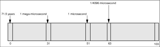
Figure 1-1 TOD format
Conceptually, the TOD clock is incremented so that a 1 (one) is added into bit position 51 every microsecond. Actual TOD-clock implementations might not provide a full 104-bit counter, but maintain an equivalent stepping rate by incrementing a different bit at such a frequency that the rate of advancing the clock is the same as though a 1 were added in bit position 51 every microsecond.
Figure 1-1 shows the stepping rate (rate at which the bit positions change) for selected TOD clock bit positions. A carry-out of bit 32 of the TOD clock occurs every 220 microseconds (1.048576 seconds). This interval is sometimes called a mega-microsecond.
The use of a binary counter for the time of day, such as the TOD clock, requires the specification of a time origin, or epoch. Epoch is the time at which the TOD clock value would have been all zeros. The z/Architecture®, ESA/390, and System/370 architectures established the epoch for the TOD clock as January 1, 1900, 0 a.m. GMT.
1.1.2 Time synchronization in a Parallel Sysplex
In z/Architecture, the STCK and STCKE instructions provide a means by which programs can both establish time-of-day and unambiguously determine the ordering of serialized events, such as updates to a database, a log file, or another data structure. The architecture requires that the TOD clock resolution be sufficient to ensure that every value stored by a STCK or STCKE instruction is unique. Consecutive STCK or STCKE instructions executed, possibly on different CPUs in the same server, must always produce increasing values. Thus, the time stamps can be used to reconstruct, recover, or in many different ways ensure the ordering of these serialized updates to shared data.
Parallel Sysplex® extended this requirement to the scope of an entire sysplex. Specifically, in a Parallel Sysplex, the processes are multisystem processes executing on different servers in the same sysplex. Therefore, time consistency must be maintained across servers. To accommodate this requirement for a Parallel Sysplex, the TOD clock architecture was extended by introducing two new major components:
•External Time References (ETR) architecture
The Sysplex Timer provides an external master clock that can serve as the primary time reference, with a link connecting each server in the Parallel Sysplex to the Sysplex Timer. The External Time References architecture link is used for both setting the local TOD clocks and maintaining time synchronization between the clocks.
•TOD-Clock Synchronization Facility
The TOD-Clock Synchronization Facility provides an interface between the operating system (OS) and the Sysplex Timer in order to allow the OS to:
– Coordinate setting the local clocks with the Sysplex Timer.
– React to losses in synchronization through an external interruption so that data integrity is maintained.
The process to achieve time consistency is:
1. Server A executes a STCK instruction (time stamp x), which places the clock contents in storage.
2. Server A signals server B.
3. Server B, on receipt of the signal, immediately executes STCK (time stamp y).
For time stamp x and time stamp y to reflect the fact that y is later than x, the two TOD clocks must agree within the time required to send the signal. The consistency required is limited by the time required for signalling between the coupled servers and the time required by the STCK instruction itself.
In practical terms, this means that the Sysplex Timer is required to keep the TOD clocks of all participating systems synchronized with each other to within a small number of microseconds, dictated by the fastest possible passing of data from one system to another through a coupling facility (CF) structure.
1.1.3 Overview of External Time Reference
|
Note: For more details on Sysplex Timer refer to S/390® Time Management and IBM 9037 Sysplex Timer, SG24-2070.
|
The IBM External Time Reference architecture provides a means of synchronizing TOD clocks in different servers with a centralized time reference, which in turn can be set accurately based on an international time standard. The architecture defines a time-signal protocol and a distribution network, called the ETR network, which permits accurate setting and maintenance of consistency of TOD clocks.
An ETR network consists of the following three elements, which are configured in a network:
•Sysplex Timer sending unit
•Sysplex Timer link
•Sysplex Timer receiving unit
The sending unit is the centralized, external time reference that transmits ETR signals over dedicated Sysplex Timer links. It also provides a means by which Sysplex Timer time can be accurately maintained with respect to external standard time services.
The receiving unit in each server receives the Sysplex Timer signals and includes the means by which the TOD clocks are set and maintained consistent with Sysplex Timer time. Figure 1-2 shows a typical ETR network, which connects the sending unit to all servers in an installation. The ETR network might comprise one or more sysplexes and servers not belonging to a sysplex.

Figure 1-2 A Typical ETR network
A fault-tolerant configuration can be provided by coupling and synchronizing two sending units with each other so that each unit transmits consistent Sysplex Timer timing information. Figure 1-3 shows a typical fault-tolerant ETR network.

Figure 1-3 Fault-tolerant ETR network
The receiving unit on each server has two ports. Each port is normally connected to a different Sysplex Timer sending unit of a coupled pair in the same network. This fully duplicated structure minimizes the potential that a single failure can adversely impact the ETR network.
1.2 Overview of Server Time Protocol
The IBM 9037 Sysplex Timer is the ETR sending unit described in 1.1.3, “Overview of External Time Reference” on page 4. It provides the synchronization for the TOD clocks of multiple servers, and thereby allows events occurring on different servers to be properly sequenced in time. When multiple servers update the same database and database reconstruction is necessary, all updates are required to be time-stamped in the proper sequence.
Some of the key limitations of the Sysplex Timer are:
•Distance limitations of the Sysplex Timer constrain the distance separation of a multi-site Parallel Sysplex.
In information technology, two important objectives for survival are:
– Systems designed to provide continuous availability
– Near transparent disaster recovery (DR)
Systems designed to provide continuous availability combine the characteristics of high availability and continuous operations to deliver high levels of service around the clock.
To attain these objectives, solutions such as GDPS3 are based on geographical clusters (such as Parallel Sysplex) and remote data mirroring across two or more data centers. An increasing number of enterprises require that the geographical cluster or Parallel Sysplex be dispersed over distances of 100 km or more to mitigate the risk that a single disaster could impact multiple data centers.
Today, in order to disperse a Parallel Sysplex over a fiber distance of 100 km, it is required that the second Sysplex Timer in a Sysplex Timer Expanded Availability Configuration be located in an intermediate site between the data centers. It should not be more than 40 km (fiber distance) away from one of the primary data centers. This is because the two timers in this configuration cannot maintain synchronization when the distance between these timers exceeds 40 km. In many cases, finding an intermediate site is not a practical solution. This limits the effective dispersion of GDPS sites to only 40 km, so that one timer can be placed in each of the two sites, with no intermediate site.
•The Sysplex Timer is required to keep the TOD clocks of all participating servers synchronized with each other to within a small number of microseconds. This value is dictated by the fastest possible passing of data from one server to another through the coupling facility structure. With the processor and coupling link technology having improved over the years, this constraint has become steadily more rigorous, dropping from a few tens of microseconds to (now) on the order of 8–10 microseconds. So far the synchronization accuracy of the Sysplex Timer has been able to stay ahead of the requirements, and thus preserve the validity of the architecture and programming model, both within a single footprint and across servers in a Parallel Sysplex. Unfortunately, this situation is now nearing an end as server and coupling link technologies keep improving.
|
Notes: The Sysplex Timer Model 2 was withdrawn from marketing effective
December 31, 2006. Enterprises that do not have a Sysplex Timer need a new methodology for time synchronization across multiple servers. The service for the Sysplex Timer Model 2 will continue beyond the withdrawal from marketing.
|
An up-to-date time synchronization must provide the following functionality:
•Improved time synchronization (compared to Sysplex Timer) for System z10 and z9 servers in a sysplex or non-sysplex configuration.
•Scale with distance. Servers exchanging messages over fast, short links require more stringent synchronization than servers exchanging messages over long distances.
•Scale with server and coupling link technologies. For example, the solution is re-used with appropriate changes when coupling link technologies change in the future.
•Support a multi-site sysplex of at least 100 km without requiring an intermediate site, and should not preclude going to longer distances in the future.
•Provide at least all the functions provided by Sysplex Timer console functions.
•Allow concurrent migration from the ETR network.
•Allow coexistence with the ETR network.
•Allow implementation into an existing Network Time Protocol (NTP) network, which may or may not utilize a pulse per second (PPS) signal.
The new time synchronization infrastructure developed by IBM for the System z environment is called Server Time Protocol.
Server Time Protocol
Server Time Protocol (STP) is a server-wide facility that is implemented in the Licensed Internal Code (LIC) of the zEC12, z196, z114, z10 EC, z10 BC, z9 EC, z9 BC, z990, and z890 servers. STP presents a single view of time to Processor Resource/Systems Manager™ (PR/SM™) and is designed to provide the capability for multiple STP configured servers to maintain time synchronization with each other. It is the follow-on to the Sysplex Timer. STP is designed to allow events occurring in different servers to be properly sequenced in time.
STP is designed for servers that have been configured in a Parallel Sysplex or a basic sysplex (without a coupling facility), as well as servers that are not in a sysplex but that must be time synchronized.
STP is a message-based protocol in which timekeeping information is passed over data links between servers. The timekeeping information is transmitted over externally defined coupling links. Coupling links that can be used to transport STP messages are the Inter System Channel-3 (ISC-3) links configured in peer mode, Integrated Cluster Bus-3 (ICB-3) links, Integrated Cluster Bus-4 (ICB-4) links, and InfiniBand (IFB) links.
STP provides the following functionality:
•Allow clock synchronization for the zEC12, z196, z114, z10 EC, z10 BC, z9 EC, z9 BC, z990, and z890 servers and CFs, without requiring the Sysplex Timer.
•Support a multi-site timing network of up to 100 km (62 miles) over fiber optic cabling, allowing a Parallel Sysplex to span these distances with no intermediate site requirement.
•Potentially reduce the cross-site connectivity required for a multi-site Parallel Sysplex.
•Coexist with an ETR network.
•Allow use of an external time source to set the time to an international time standard, such as Coordinated Universal Time, as well as adjust to the time standard on a periodic basis.
•Allow setting of local time parameters, such as time zone and daylight saving time (DST).
•Allow automatic updates of daylight saving time.
|
Note: The z12EC is the last server to support connections to a Mixed CTN. However, it cannot be configured in the same CTN with any of the following servers: z9 EC, z9 BC, z990 or z890.
|
Software support for STP is available in all supported z/OS releases with applicable PTFs.
1.3 STP concepts and terminology
This section provides an overview of some of the new concepts and terminology related to STP that did not exist with the ETR network. Understanding this new vocabulary will assist you in successfully planning a timing network based on STP.
1.3.1 STP facility
STP provides the means by which the TOD clocks in various systems can be synchronized using messages transported over links. STP operates in conjunction with the TOD-clock steering facility, providing a new timing mode, timing states, external interrupts, and machine check conditions.
TOD-clock steering facility
The TOD-clock steering facility provides a means to change the apparent stepping rate of the TOD clock without changing the physical hardware oscillator that steps the physical clock. This is accomplished by means of a TOD-offset register that is added to the physical clock to produce a logical-TOD-clock value.
TOD-clock steering permits the timing facility control program to adjust the apparent stepping rate of the TOD clock. In normal operation, the update is performed frequently so that the effect, as observed by the program, is indistinguishable from a uniform stepping rate.
The total steering rate is made up of two components:
•Fine-steering rate
The fine-steering rate is used to correct the inaccuracy in the local oscillator, which is stable over a relatively long period of time. The value normally is less than the specified tolerance of the local oscillator. The change occurs infrequently (on the order of once a day to once a week) and is small.
•Gross-steering rate
The gross-steering rate is used as a dynamic correction for all other effects, the most predominant being to synchronize time with an external time source or with other clocks in the timing network. The value normally changes frequently (on the order of once per second to once per minute).
1.3.2 TOD clock synchronization
This section provides definitions of the timing mode, timing state, and STP clock source state when the STP feature is installed.
Timing mode
The timing mode specifies the method by which the TOD clock is maintained for purposes of synchronization within a timing network. A TOD clock operates in one of the following timing modes:
•Uninitialized
When the server is in uninitialized timing mode, the TOD clock has not been initialized. The server is not part of a synchronized timing network.
•Local
When the server is in local timing mode, the TOD clock is initialized to a local time and is stepped at the rate of the local hardware oscillator. The server is not part of a synchronized timing network.
•ETR
When the server is in ETR timing mode, the TOD clock is initialized to the Sysplex Timer and is being stepped by stepping signals from the Sysplex Timer. To be in ETR timing mode, the server must be part of an ETR network.
•STP
When the server is in STP timing mode, the TOD clock is initialized to Coordinated Server Time (CST) and is stepped at the rate of the local hardware oscillator. In STP timing mode, the TOD clock is steered so as to maintain, or attain, synchronization with CST. To be in STP-timing mode, the server must be part of an STP network. Refer to 1.3.4, “Coordinated Timing Network” on page 11, for an explanation of CST.
Timing states
The timing state indicates the synchronization state of the TOD clock with respect to the timing network reference time. The timing states are:
•Synchronized
When a server is in the synchronized timing state, the TOD clock is in synchronization with the timing-network reference time as defined here:
– If the server is in ETR timing mode, the server is synchronized with the Sysplex Timer.
– If the server is in STP timing mode, the server is synchronized with CST.
– A server that is in the local timing or uninitialized timing mode is never in the synchronized state.
•Unsynchronized
When a server is in the unsynchronized timing state, the TOD clock is not in synchronization with the timing network reference time as defined here:
– If the server is in ETR timing mode, the server has lost synchronization with the Sysplex Timer.
– If the server is in STP timing mode, the server has lost or has not been able to attain synchronization with Coordinated Server Time. The server is out of synchronization with CST when the TOD clock differs from CST by an amount that exceeds a model-dependent synchronization threshold value.
•Stopped
When a server is in the stopped state, the TOD clock is either in the stopped state or TOD-clock recovery is in progress. When the TOD-clock recovery is completed, the TOD clock enters either the synchronized or unsynchronized state.
STP clock source state
The STP clock source state indicates whether a usable STP clock source is available. The STP clock source is used to determine the Coordinated Server Time required to be able to synchronize the TOD clock.
•Not usable
The not usable STP clock source state indicates that a usable STP clock source is not available to STP. When a usable STP clock source is not available, CST cannot be determined.
•Usable
The usable STP clock source state indicates that a usable STP-clock source is available to STP. When a usable STP-clock source is available, CST has been determined and can be used to synchronize the TOD clock to the STP network.
1.3.3 STP servers
In this section we discuss STP servers.
STP capable
An STP-capable server is a server that has all required LIC to support STP installed. IBM System zEC12, z196, z114, z10 EC, z10 BC, z9 EC, z9 BC, and zSeries® 990 and 890 with the required LIC installed are STP capable.
STP enabled
An STP-enabled server is an STP-capable server that has the STP function enabled. Even after LIC to support STP is installed on a server, the STP function cannot be used until it is enabled.
STP configured
An STP-configured server is a server that has been configured to be part of a CTN by assigning it a CTN ID. When the STP network ID field is not specified, the server is not configured to be part of a CTN, and is therefore not an STP-configured server. CTN and CTN ID are discussed in the next section.
1.3.4 Coordinated Timing Network
A Coordinated Timing Network (CTN) contains a collection of servers that are time synchronized. They are time synchronized to a time value called Coordinated Server Time (CST). The CST represents the time for the entire network of servers.
The servers that make up a CTN are all configured with a common identifier, referred to as a CTN ID. Only servers with the same CTN ID are allowed to become members of the CTN. Servers with different CTN IDs can be members of different Coordinated Timing Networks. All servers in a CTN maintain an identical set of time control parameters that are used to coordinate the TOD clocks.
A CTN can be configured as either:
•STP-only CTN
An STP-only CTN (described later in 1.4.2, “STP-only CTN” on page 18) is a timing network in which all servers are configured to be in STP timing mode. It can only be configured with STP-capable servers, and none of the servers can be in ETR timing mode.
•Mixed CTN
A Mixed CTN (described later in 1.4.1, “Mixed CTN” on page 14) allows the coexistence of servers and CFs synchronized in an ETR network, with servers and CFs that are synchronized with CST. The Sysplex Timer provides the timekeeping information in a Mixed CTN.
CTN ID
The CTN ID is an identifier that is used to indicate whether the server has been configured to be part of a CTN and, if so configured, identifies the CTN. The CTN ID is made up of two fields:
•A field that defines the STP network ID
•A field that defines the ETR network ID
These fields are of the format STP network ID and ETR network ID, as illustrated on Figure 1-4 (the hyphen is used to identify each field. it is not part of the CTN ID).

Figure 1-4 Coordinated Timing Network ID (CTN ID)
The Hardware Management Console (HMC) is used to enter the CTN ID. See Figure 1-5.

Figure 1-5 CTN ID
When both fields are specified, the CTN is referred to as a Mixed CTN. When the STP network ID field is specified but the ETR network ID field is not specified (set to null or blank), the CTN is referred to as an STP-only CTN.
For servers that do have the External Time Reference feature for Sysplex Timer attachment installed (z10 EC, z10 BC, z9 EC, z9 BC, z990 and z890), the ETR network ID is configured in the ETR Configuration tab. The ETR Configuration tab and the ETR Status tab are not available for servers zEC12, z196 and z114 (as seen in Figure 1-5) since the ETR feature is not installed, nor available in these servers.
1.3.5 STP stratum
The term stratum is found throughout this document and within the Hardware Management Console panels.
The Sysplex Timer distributes time to multiple servers in a star pattern. That is, the Sysplex Timer is the star, and its time signals emanate out from it to all attached servers. The signals from the Sysplex Timer are used to increment or step the TOD clocks in the attached server.
Unlike the Sysplex Timer, STP distributes time messages in layers, or stratums. The top level (stratum 1) distributes time messages to the layer immediately below it (stratum 2). Stratum 2 in turn distributes time messages to stratum 3. More layers are conceivably possible, but the current STP implementation is limited to three layers. Figure 1-6 illustrates the stratum concept.
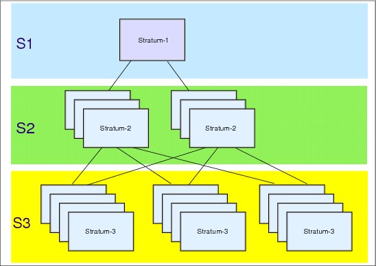
Figure 1-6 STP stratum levels
STP Stratum levels
In a timing network based on STP, stratum are used as a means to define the hierarchy of a server in the timing network. A stratum 1 server is the highest level in the hierarchy in the STP network.
The stratum 1 level is determined indirectly in one of the following ways:
•In a Mixed CTN, any STP-configured server synchronized to the Sysplex Timer is a Stratum 1 server. A Mixed CTN is allowed to have multiple Stratum 1 servers. Refer to 1.4, “Timing network types” on page 14 for more details.
•In an STP-only CTN, the roles of Preferred and Current Time Servers are assigned, and the Current Time Server becomes the active stratum 1 server. Details regarding Preferred and Current Time Servers are in 1.3.6, “Server roles in an STP-only CTN” on page 14.
Stratum 2 and stratum 3 levels are determined by how many stratum levels they are away from stratum 1. A server that uses STP messages to synchronize to a stratum 1 server is referred to as a stratum 2 server. Similarly, a server that uses STP messages to synchronize to a stratum 2 server is referred to as a stratum 3 server.
|
Note: Throughout the book you will also find STP stratum 0 (S0). This refers to the unsynchronized state of a server (CEC).
|
1.3.6 Server roles in an STP-only CTN
Unlike a Mixed CTN, which can have multiple stratum 1 servers, an STP-only CTN can have only one active stratum 1 server. The following definitions explain the roles that must be assigned (through the HMC interface) for certain servers in an STP-only CTN.
Preferred Time Server (PTS)
Using the STP panels provided at the HMC, a server must be assigned that has preference to be the stratum 1 server of an STP-only CTN. This is the Preferred Time Server. This server should have connectivity to the Backup Time Server and the Arbiter, as well as to all servers that are planned to be stratum 2 servers. The connectivity can be either ISC-3 links in peer mode, ICB-3 links, ICB-4 links, or IFB links.
Backup Time Server (BTS)
Although optional, we strongly recommend also assigning a Backup Time Server whose role it is to take over as the stratum 1 server should the PTS fail. The Backup Time Server is a stratum 2 server that should have connectivity to the Preferred Time Server and the Arbiter, as well as to all other stratum 2 servers that are connected to the Preferred Time Server.
Current Time Server (CTS)
The Current Time Server is the active stratum 1 server in an STP-only CTN.
|
Note: There can only be one active stratum 1 server in an STP-only CTN, and only the Preferred Time Server or the Backup Time Server can be assigned to be the active Stratum 1 server.
|
The Current Time Server can be assigned (only) to either the Preferred Time Server or the Backup Time Server. We recommend that the Current Time Server be assigned to the Preferred Time Server when the configuration is being initialized. Subsequently, if there is a need to reassign the roles, the Current Time Server can be concurrently assigned to the Backup Time Server. This action can be part of a planned reconfiguration of the Preferred Time Server as long as the planned action is not disruptive.
Arbiter
Optionally, a server might be assigned the role of Arbiter. The Arbiter provides additional means for the Backup Time Server to determine whether it should take over as the Current Time Server in the case of unplanned events that affect the CTN. The Arbiter is a stratum 2 server that must have connectivity to both the PTS and the BTS.
1.4 Timing network types
•STP-only CTN, which does not require a Sysplex Timer
Refer to 1.1.3, “Overview of External Time Reference” on page 4, for a brief description of an ETR network.
1.4.1 Mixed CTN
As mentioned earlier, it is essential that STP supports a concurrent migration from an existing ETR network to an STP-based one. STP is implemented in the LIC of the zEC12, z196, z114, z10 EC, z10 BC, z9 EC, z9 BC, z990, and z890 servers.
It is also crucial that STP allow servers and coupling facilities that are synchronized with the Sysplex Timer (ETR network) and servers and CFs that are synchronized with Coordinated Server Time to be synchronized with each other in the same network.
In order to meet these two important requirements, the STP design allows the formation of a Mixed Coordinated Timing Network (Mixed CTN). The Sysplex Timer provides timekeeping information in a Mixed CTN.
The minimum requirements to configure a Mixed CTN are:
•There must be at least one STP-enabled server. To reiterate, an STP-capable server that has the STP function enabled is referred to as an STP-enabled server.
|
Important: In order to avoid a single point of failure in a Mixed CTN, the recommendation is to have a minimum of two STP-configured servers stepping to timing signals received from the Sysplex Timers before configuring any server using STP messages for synchronization.
|
•The STP-enabled servers must be attached to a Sysplex Timer or a pair of Sysplex Timers configured in an Expanded Availability configuration. Since the Sysplex Timer provides the timekeeping information in a Mixed CTN, at least one STP-enabled server in the Mixed CTN must be stepping to timing signals provided by the Sysplex Timer before additional servers or CFs can be STP configured.
•The STP-enabled servers must be configured with the same CTN ID, with the format [STP network ID] - [ETR network ID]. The STP network ID can be from 1 to 8 characters long. Valid characters are A–Z, a–z, 0–9, ‘-’, and ‘_’. The ETR network ID is the same as the ETR network ID of the Sysplex Timers to which the servers are attached. After the CTN ID is assigned, the servers are now STP-configured servers.
|
Note: A CTN is configured only after the servers become STP-configured.
|
Figure 1-7 shows an example of a Mixed CTN consisting of two STP-configured servers, a z10 EC, and a z9 BC. Both servers are synchronized by one of the attached Sysplex Timers, whose ETR network ID is 31.

Figure 1-7 Mixed CTN, stratum 1 servers only
In this example, the z10 EC and the z9 EC have been assigned the same CTN ID = [ITSOPOK] - [31] and are therefore in a Mixed CTN, with the Sysplex Timer providing the timekeeping information. The servers are in ETR timing mode. If coupling links are configured between the z10 EC and the z9 EC, then STP messages are exchanged by the two servers. As described in “STP Stratum levels” on page 13, the z10 EC and the z9 EC become stratum 1 servers in the Mixed CTN. The z9 BC has not been STP-enabled, however, it is attached to the same pair of Sysplex Timers (ETR Network ID =31). The z9 BC is therefore in an ETR network and can coexist with the servers that are in the Mixed CTN.
Each Stratum 1 server receives time-control parameters from the attached Sysplex Timer (or timers) and propagates the information to stratum 2 servers, which in turn propagate the information to stratum 3 servers. Time-control parameters for a configuration include:
•Total-time offset (the combination of time-zone offset and DST offset)
•Leap seconds offset
In a Mixed CTN, the Sysplex Timer console provides the user interface for all time-related functions, such as time initialization, time adjustment, and so on. This is not different from the operations in an ETR-only network. However, the HMC must be used to initialize or modify the CTN ID. In a Mixed CTN if there is a requirement for time accuracy, the external time source (ETS) function is provided by attaching the ETS device to the Sysplex Timer.
Servers configured in STP timing mode
Once the minimum requirements described in the previous section have been met, additional servers can be added to the Mixed CTN without these servers requiring connectivity to the Sysplex Timers. Servers in the CTN that are synchronized using STP messages, and not stepping to the Sysplex Timer, are stratum 2 or stratum 3 servers.
If you have more than two stratum 1 servers in a Mixed CTN configuration (all stratum 1 are directly connected to the Sysplex timers), to migrate these servers to STP timing mode, disable their ETR ports. These servers maintain time synchronization using STP protocol via coupling link connectivity to the remaining stratum 1 servers.
The servers that are planned to be configured in STP timing mode must meet the following requirements:
•They must be configured with the same CTN ID as the servers stepping to the Sysplex Timer. These are the stratum 1 servers.
•They must have coupling link connectivity (ISC-3 Peer, ICB-3, ICB-4, or IFB) to the servers to which they are planned to be synchronized.
In Figure 1-8, an additional server is configured with the same CTN ID as the Mixed CTN shown in Figure 1-7 on page 16.
The STP-enabled z10 BC is assigned a CTN ID = [ITSOPOK] - [31]. Also, ISC-3 Peer links are configured between the z10 BC and the z10 EC as well as between the z10 BC and the z9 EC. STP algorithms determine whether the z10 BC will synchronize to the z10 EC or the z9 BC. Redundancy of stratum 1 servers is provided to allow the z10 BC server to stay within the Mixed CTN in the event that either the z10 EC or z9 EC has a planned or unplanned outage.

Figure 1-8 Mixed CTN, stratum 1 and stratum 2 servers
When the Mixed CTN configuration is active, the Sysplex Timer provides the timekeeping information. The z10 EC and z9 EC are synchronized to the Sysplex Timers via the ETR links and are in ETR timing mode. The z10 BC is synchronized to either the z10 EC or the z9 EC by exchanging STP messages over the coupling links, and is in STP timing mode.
|
Note: zEC12 servers are not supported in the same CTN with z9 or earlier servers.
|
Parallel Sysplex configuration in a Mixed CTN
A Parallel Sysplex configuration requires that all servers in the sysplex are time coordinated. Figure 1-9 shows a Parallel Sysplex comprising z/OS images P1, P2, P3, P4, and P5, along with two Internal coupling facilities (ICFs).

Figure 1-9 Mixed CTN Parallel Sysplex example
|
Note: zEC12 servers are not supported in the same CTN with z9 or earlier servers.
|
The coupling links used for CF messaging between servers, as shown in Figure 1-9, can also be used for STP message exchanges. It is possible to configure the CTN so that additional coupling links are not required to specifically transport STP messages. The same coupling links are also used for STP message exchanges. The z/OS image P5, located in the z9 BC server that is not STP-enabled, maintains time synchronization from the Sysplex Timer.
|
Note: Since STP configuration allows stratum 3 servers in a CTN (even though Figure 1-8 and Figure 1-9 show only two stratum levels), the CTN can be further extended by synchronizing a stratum 3 to the stratum 2 server.
|
1.4.2 STP-only CTN
An STP-only CTN is a timing network in which all servers are configured to be in STP timing mode. None of the servers in an STP-only CTN can be in ETR timing mode. Therefore, an STP-only CTN can only be configured with STP-enabled servers, and the Sysplex Timer does not provide stepping signals to any servers in this network. As a minimum, before an STP-only CTN configuration can become active and servers can exchange timekeeping messages, the following conditions must exist:
•There must be at least one STP-enabled server in order to configure an STP-only CTN. To reiterate, an STP-capable server that has STP function enabled is referred to as an STP-enabled server.
•The STP-enabled servers must be configured with the same CTN ID, with the format [STP network ID] - [ETR network ID]. The STP network ID can be from 1 to 8 characters long. The valid characters are A–Z, a–z, 0–9, '-', and '_'. In an STP-only CTN, the ETR network ID must not be specified. For example, a valid CTN ID could be [STPCONFG] - [ ]. After the CTN ID is assigned, the servers are now considered to be STP configured.
|
TIP: The STP network ID is case-sensitive.
|
•Assign the Preferred Time Server and the Current Time Server. The server that is assigned the role of the Current Time Server becomes the active stratum 1 when an STP-only CTN configuration is completed. In most cases, the Preferred Time Server is assigned to also be the Current Time Server.
•Optionally, a Backup Time Server can be assigned. If a Backup Time Server is assigned, an Arbiter can be assigned as well if there are three or more servers in the STP CTN.
The servers that are planned to be synchronized to either the Preferred Time Servers or the Backup Time Servers need coupling link connectivity (ISC-3 Peer, ICB-3, ICB-4, or IFB). All servers in an STP-only CTN are in STP timing mode.
|
Note: ISC links are not supported on zEC12 servers.
|
In an STP-only CTN, the HMC provides the user interface for all time-related functions, such as time initialization, time adjustment, offset adjustment, and so on. The HMC must also be used to initialize or modify the CTN ID. For time accuracy, the external time source (ETS) function is also provided. In certain cases, the HMC is also used to provide Console Assisted Recovery (CAR).
Preferred Time Server only
Figure 1-10 shows an STP-only CTN where the zEC12 is assigned as the Preferred Time Server. A Backup Time Server is not assigned, and therefore an Arbiter cannot be assigned either. Since only the Preferred Time Server or the Backup Time Server can be the Current Time Server, in this example the Preferred Time Server must be the Current Time Server. Redundant coupling link connectivity is provided as shown from each of the other servers (z196 and z114) to the zEC12.

Figure 1-10 STP-only CTN (Preferred Time Server only)
When an STP-only CTN configuration becomes active:
•The zEC12 becomes the stratum 1 server.
•The z196 and z114 become stratum 2 servers.
|
Note: In this example, without a Backup Time Server assigned, the loss of the Preferred Time Server results in the loss of synchronized time in the CTN until the Preferred Time Server is restored or a new configuration is defined.
|
In an STP-only CTN, time-control parameters are provided via the Hardware Management Console or Support Element panels. The time-control parameters must be sent to the Current Time Server in the CTN. The Current Time Server receiving the parameters propagates the parameters to each server in the CTN. Time-control parameters for a configuration include:
•Leap seconds offset
•Time zone offset
•Daylight saving time offset
•Scheduled changes to any of these offsets
Preferred and Backup Time Servers
Figure 1-11 shows an example of an STP-only CTN where the zEC12 is assigned as the Preferred Time Server, the z114 is assigned as the Backup Time Server, and an Arbiter is not assigned. Either the Preferred Time Server or the Backup Time Server is assigned as the Current Time Server. In this example, the Preferred Time Server is assigned as the Current Time Server (CTS).
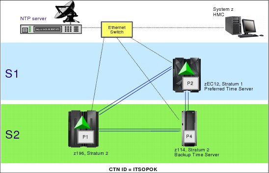
Figure 1-11 STP-only CTN (Preferred Time Server and Backup Time Servers)
In this example, redundant coupling links should be provided from the z196 to not only the zEC12, but also to the z114, which has been assigned as the Backup Time Server. By providing this connectivity, the z196 can maintain synchronization when the PTS (zEC12) fails and the BTS (z114) takes over as the CTS.
Preferred, Backup, and Arbiter servers
Figure 1-12 shows an example of an STP-only CTN where the zEC12 is assigned as the Preferred Time Server, the z114 is assigned as the Backup Time Server, and the z196 is assigned as an Arbiter. Either the Preferred Time Server or the Backup Time Server can be assigned as the Current Time Server. In this example, the Preferred Time Server is assigned as the Current Time Server. The Arbiter provides additional means for the Backup Time Server to determine whether it should take over as the Current Time Server in the event of unplanned exception conditions.

Figure 1-12 STP-only CTN (Preferred, Backup, Arbiter)
Figure 1-12 also shows three z/OS systems configured in a Parallel Sysplex: P1, P2, and P3.
Since the two CFs reside on the zEC12 and z196, the coupling links provide connectivity for both the CF and STP message exchanges.
1.5 Coupling links
STP is a message-based protocol in which time-keeping information is passed over data (coupling) links between servers. The time-keeping information provides the means for STP to determine an estimate of the time-of-day clock for the CTN, referred to as CST. The time-keeping information is transmitted over externally defined coupling links. Coupling links provide the transmission characteristics required for STP synchronization requirements. Coupling links that can be used to transport STP messages are the InterSystem Channel-3 (ISC-3) links in Peer mode, the Integrated Cluster Bus (ICB-4) or (ICB-3) links, or InfiniBand (IFB) links.
The advantages of using coupling links to exchange STP messages are:
•By using the same links to exchange timekeeping information and CF messages in a Parallel Sysplex, STP can meet the requirement stated in 1.2, “Overview of Server Time Protocol” on page 6, that STP must scale with distance. Servers exchanging messages over ICB-3, ICB-4, and IFB links can now meet more stringent synchronization requirements than servers exchanging messages over long ISC-3 links (distances up to 100 km), where the synchronization requirements are less stringent.
•Coupling links also provide the connectivity needed in a Parallel Sysplex. Therefore, there is a potential benefit of minimizing the number of cross-site links required in a multi-site Parallel Sysplex.
The following types of STP messages are carried over the coupling links:
•Time parameter messages:
Time parameter messages are used to exchange the timekeeping information needed to determine Coordinated Server Time at each server. The time parameter messages are used to exchange timestamps, time-keeping information, and CTN-parameter information between two directly attached servers. The information in the message response is used by the message originator to calculate the round-trip delay, offset, and dispersion values that are used by STP clock filtering and selection algorithms to select a clock source.
Time parameter messages are used to exchange the timekeeping information needed to determine Coordinated Server Time at each server. The time parameter messages are used to exchange timestamps, time-keeping information, and CTN-parameter information between two directly attached servers. The information in the message response is used by the message originator to calculate the round-trip delay, offset, and dispersion values that are used by STP clock filtering and selection algorithms to select a clock source.
•Control messages:
Control messages are used to set and modify various Coordinated Timing Network parameters required by servers in the CTN. They are used to request CTN parameter updates, to establish and remove STP paths, and to read configuration information from attached servers.
Control messages are used to set and modify various Coordinated Timing Network parameters required by servers in the CTN. They are used to request CTN parameter updates, to establish and remove STP paths, and to read configuration information from attached servers.
1.5.1 Link redundancy
We recommend that at least two coupling links are configured for communication between any two servers that are intended to exchange STP messages. This prevents the loss of one link causing the loss of STP communication between the servers. There is no architectural limit to the maximum number of links that can be defined. The limit is based on what is supported by each server in the configuration.
The maximum number of attached servers supported by any STP-configured server in a CTN is equal to the maximum number of coupling links supported by the servers in the configuration. Not considering redundancy recommendations, this value is equal to the maximum number of combined ISC-3, ICB-3, ICB-4, and IFB links. Up to 128 combined coupling links are supported on the zEC12, z196, and z114, while up to 64 combined coupling links are supported on the z10 EC, z10 BC, z9 EC, z9 BC, z990, and z890.
1.5.2 Coupling link requirements in a non-sysplex configuration
Time coordination is required by other applications besides the sysplex and Parallel Sysplex configurations. One example of time coordination requirements when a Parallel Sysplex configuration does not necessarily exist is the remote copy technology referred to as z/OS Global Mirror (previously called Extended Remote Copy (XRC)). z/OS Global Mirror is a combined hardware and software asynchronous remote copy solution. The application I/O is signaled complete when the data update to the primary storage is completed.
Subsequently, a DFSMSdfp component called System Data Mover (SDM) asynchronously offloads data from the primary storage subsystem’s cache and updates the secondary disk volumes. Typically, the production systems are in site 1 and the data is being mirrored to a Disaster Recovery site (site 2). The production systems located in site 1 can be a single system, multiple systems sharing disk, or a base or Parallel Sysplex cluster. For more information about IBM DFSMSdfp, see:
http://www-03.ibm.com/systems/storage/software/sms/dfp/index.html
Data consistency across all primary and secondary volumes spread across any number of storage subsystems is essential for providing data integrity and the ability to do a normal database restart in the event of a disaster. Data consistency in a XRC environment is provided by the Consistency Group (CG) processing performed by the SDM. The CG contains records that have their order of update preserved across multiple Logical Control Units within a storage subsystem and across multiple storage subsystems. CG processing is possible only because each update on the primary disk subsystem has been time-stamped. If multiple systems on different servers are updating the data, time coordination is required across the different servers in each site. This requirement can be met either by the Sysplex Timer or STP. Time coordination is not required across the two sites that have the primary and secondary disk subsystems.
Figure 1-13 shows a GDPS/XRC configuration. More information about XRC and GDPS/XRC, a solution that automates the recovery of production systems when a disaster takes place, can be found at:

Figure 1-13 GDPS/XRC configuration
For a server that is not part of a Parallel Sysplex but that must be in the same CTN, additional coupling links must be configured in order for the server to be configured in the CTN. Hardware configuration data (HCD) has been enhanced to permit special timing-only links and control units to be defined. The timing-only links can be of type CFP for ISC-3 in peer mode, or CBP for ICB-3/ICB-4, or CIB for IFB (Example 1-1). The control unit type is STP and it has no devices defined to it. If a coupling facility link already exists between two servers, the STP control unit type cannot be defined. Likewise, if the STP control unit type is defined, a new CF Link cannot be defined unless the STP control unit is removed. For more details refer to 2.2.2, “Planning for timing-only links” on page 44.
Example 1-1 Coupling links
--------Source-------- ---------Destination--------- -CU- -#-
/ CHPID CF Type Mode Occ Proc.CSSID CHPID CF Type Mode Type Dev
_ 83 Y CIB SHR N SCZP401.0 B2 Y CIB SHR CFP 7
_ 88 Y CIB SHR N SCZP401.0 B6 Y CIB SHR CFP 7
_ A2 N CFP SHR N SCZP201.2 A7 N CFP SHR STP
_ A3 N CFP SHR N SCZP201.2 AC N CFP SHR STP
1.6 External time source
If there are specific requirements to provide accurate time relative to an external time standard for data-processing applications, then consider using the external time source (ETS) function of STP. For servers in an ETR network or a Mixed CTN, the ETS function is provided by the Sysplex Timer. Refer to Planning for the 9037 Model 2, SA22-7233, for details. For servers in an STP-only CTN the external time source can be configured in one of the following ways:
•Dial out from the HMC to an available time service such as Automated Computer Time Service (ACTS). Accuracy of 100 milliseconds to the time provided by the time service can be obtained. The dial out option is available up to HMC Version 2.11.1 - starting with HMC Version 2.12.0 the dial out option is no more available since this HMC does not support a modem connection.
•Interface with an NTP server to maintain Coordinated Server Time accuracy of 100 milliseconds to the time provided by the NTP server. Simple Network Time Protocol (SNTP) client support is available on the IBM System zEC12, z196, z114, z10, z9 EC and z9 BC Support Elements to interface with NTP servers. It is also possible to configure the HMC as an NTP server. HMC Authentication Support is available starting with HMC Version 2.12.0 and provides NTP security either per Symmetric key (NTP Version 3 and 4) or Autokey (NTP Version 4).
•Interface with an NTP server with a pulse per second (PPS) output option. STP has been designed to track to the highly stable, accurate PPS signal from NTP servers that provide this output and maintain accuracy of 10 microseconds as measured at the PPS input of the System z server.
NTP client support addresses the requirements of customers who need to provide the same time across heterogeneous platforms in an enterprise. Dialing out provides time accuracy for the System z platform only, whereas attaching to an NTP server allows time accuracy as well as the same reference time source across heterogeneous platforms. In order to provide customers with the capability to enhance the STP time accuracy to an external time source, an option is available to configure an NTP server with a pulse per second output at the ETS. This type of ETS device is available worldwide from several vendors that provide network timing solutions. NTP client support and support of PPS are available on the zEC12, z196, z114, z10 EC, z10 BC, z9 EC, and z9 BC configured in an STP-only Coordinated Timing Network.
The z990 and z890 servers do not support NTP (with or without the PPS option) as an external time source, however, they can use dial-out from the HMC. They can also participate in an STP-only CTN that has a IBM System z10 EC, Z10 BC or z9 configured to use NTP as an external time source.
|
Restriction: When ordering a new server (at the time of this publication zEC12, z196, or z114 can be ordered), the default HMC shipped with the order is 2.12.0 or above. If you still plan to use dial-out to a time service, you need to use an HMC that has not been upgraded to this level. In this case, you need to plan your CTN accordingly.
|
The Network Time Protocol was introduced in the early 1980s as part of the early development of Internet technology. NTP is used to synchronize the time of a computer to a time server or another time source reference. Developed over the last three decades, it provides accuracies typically within a millisecond on Local Area Networks (LANs) and up to a few tens of milliseconds on Wide Area Networks (WANs) relative to UTC. A timing signal can be obtained from a Global Positioning Service (GPS) receiver, a radio service, or another highly accurate time source4. A complete description of NTP can be found at the Web site:
NTP stratum
In an NTP-based network the servers are defined by stratum and are hierarchically arranged. In a CTN only three levels of stratum are supported or available, while the servers in an
NTP V4 network can have an upper limit of 15.
NTP V4 network can have an upper limit of 15.
A reference clock (for example, cesium clock, Global Positioning System, terrestrial broadcasts) itself is defined as stratum 0. A server directly attached to a reference clock is a stratum 1.
|
Attention: The NTP stratum level is completely independent of the STP stratum level. Although both STP and NTP use the term stratum, there is no direct relationship between the two.
For clarity, subsequently in this book we refer to STP stratum for server (CEC) stratum level in a CTN, and NTP stratum for referring to the NTP servers used as External Time Source.
|
Another requirement is high availability. NTP stratum 2 servers receive their time from one or more stratum 1 servers and are, according to the NTP Public Service Project, not significantly less accurate than a stratum 1 server. See Figure 1-14.

Figure 1-14 Stratum levels in an NTP network
For information about NTP servers see the NTP Public Services Project Web page:
1.7 Summary of STP terminology
Table 1-1 provides a summary of the STP terminology, acronyms that are used in this document, and some usage notes that facilitate understanding of the terminology.
Table 1-1 Summary of STP terminology
|
Name
|
Acronym
|
Description
|
Usage notes
|
|
Arbiter
|
|
Server assigned by the customer to provide additional means for the Backup Time Server to determine whether it should take over as the Current Time Server.
|
A stratum 2 server that must be attached to both the Preferred Time server and the Backup Time Servers.
|
|
Backup Time Server
|
BTS
|
Server assigned by the customer to take over as the Current Time Server (stratum 1 server) because of a planned or unplanned reconfiguration.
|
A stratum 2 server that must be attached to the Preferred Time Server and the Arbiter, as well as all the servers that are attached to the Preferred Time Server.
|
|
Coordinated Server Time
|
CST
|
The Coordinated Server Time in a CTN represents the time for the CTN. CST is determined at each server in the CTN.
|
|
|
Coordinated Timing Network
|
CTN
|
A network that contains a collection of servers that are time synchronized to CST.
|
•All STP-configured servers in a CTN must have the same identifier, referred to as a CTN ID.
•Use CTN when there is no need to distinguish between a Mixed CTN and an STP-only CTN.
|
|
Coordinated Timing Network Identifier
|
CTN ID
|
Identifier that is used to indicate whether the server has been configured to be part of a CTN and, if so, identifies that CTN.
|
Made up of two fields:
•Field that defines STP network ID
•Field that defines ETR network ID
|
|
Current Time Server
|
CTS
|
A server that is currently the stratum 1 for an STP-only CTN.
|
Only the Preferred Time Server or the Backup Time Server can be a Current Time Server.
|
|
ETR network
|
|
A network that contains a collection of servers that are time synchronized to the Sysplex Timer.
|
All servers in the ETR network must have the same ETR network ID.
|
|
ETR network ID
|
|
An identifier assigned to a pair of synchronized Sysplex Timers. It is also the second field of a CTN ID whose low order 5 bits define the ETR network for which the server is configured.
|
ETR network ID 00 to 31, if the server is part of the ETR network, and not specified when STP-only CTN is configured.
|
|
ETR timing mode
|
|
The TOD clock has been initialized to the Sysplex Timer and is being stepped by stepping signals from the Sysplex Timer.
|
The server can be part of an ETR network or a stratum 1 server in a Mixed CTN.
|
|
External time source
|
ETS
|
The time source used to set and maintain the Coordinated Server Time close to an international time standard such as UTC.
|
The ETS can be a dial-out time service, an NTP server, or an NTP server with pulse per second output.
|
|
Local timing mode
|
|
The TOD clock has been initialized to a local time and is being stepped at the rate of the local hardware oscillator.
|
The server is not part of a synchronized timing network.
|
|
Mixed Coordinated Timing Network
|
Mixed CTN
|
The timing network that contains a collection of servers and has at least one STP-configured server stepping to timing signals provided by the Sysplex Timer. STP-configured servers in the Mixed CTN not stepping to the Sysplex Timer achieve synchronization by exchanging STP messages.
|
The CTN ID must be a valid STP-network ID and the ETR Net ID must be in the range 00–31.
|
|
Network Time Protocol
|
NTP
|
A protocol used to synchronize timekeeping among a set of time servers and clients.
|
See RFC-1305.
|
|
Preferred Time Server
|
PTS
|
The server assigned by the customer to be the preferred stratum 1 server in an STP-only CTN.
|
Usually the Current Time Server in an STP-only CTN. Planned or unplanned reconfiguration can result in the Backup Time Server being the Current Time Server.
|
|
Pulse per second
|
PPS
|
A highly stable and accurate output of some NTP servers to provide enhanced time accuracy for the CST.
|
The PPS input port is located on the ETR card of the System z10 and z9 servers.
|
|
Simple Network Time Protocol
|
SNTP
|
An adaptation of the Network Time Protocol.
|
See RFC-4330.
|
|
STP network ID
|
|
The first field of the CTN ID that defines the STP network that the server is configured for.
|
When the STP-network ID is not specified, the server is not configured to be part of a CTN.
|
|
STP timing mode
|
|
The TOD clock has been initialized to CST and is being stepped at the rate of the local hardware oscillator, and is steered so as to maintain, or attain, synchronization with CST.
|
The server must be part of an STP CTN. In a Mixed CTN, only stratum 2 or 3 servers can be in STP timing mode.
|
|
STP-capable server
|
|
The server that has Licensed Internal Code (LIC) to support STP protocol.
|
The zEC12, z196, z114, z10 EC, z10 BC, z9 EC, z9 BC, z990, and z890 servers can be STP capable.
|
|
STP-enabled server
|
|
The STP-capable server that has STP function enabled.
|
|
|
STP-configured server
|
|
The STP-enabled server that has a CTN ID defined.
|
|
|
STP-only Coordinated Timing Network
|
STP-only CTN
|
The timing network that contains a collection of servers configured to be in STP timing mode. None of the servers in an STP-only CTN can be in ETR timing mode.
|
The CTN ID must be a valid STP-network ID and the ETR Net ID must not be specified. None of the servers are configured to be part of an ETR network.
|
|
Stratum
|
|
A means to identify the hierarchy of the server within the STP CTN or NTP server timing network.
|
The customer does not assign the stratum directly on a panel. Refer to STP stratum for server (CEC) stratum level in a CTN, and NTP stratum for the NTP servers used as External Time Source.
|
|
Stratum 0 server
|
|
An STP stratum level of zero is used to indicate that the stratum level is undefined in an STP-only CTN. This convention differs from an NTP stratum 0 server, which identifies a physical primary time source that is assumed to be accurate and has little or no delay associated with it.
|
Generally, to indicate that the CTN ID of a server is still undefined. If the CTN ID is defined, it means that the server does not have a usable clock source.
|
|
Stratum 1 server
|
|
STP stratum 1 is the highest level in the hierarchy of a timing network that uses STP messages for synchronization. This convention differs from an NTP Stratum 1 server, which identifies a server that is attached to an NTP Stratum 0 server and typically acts as a server for timing requests from NTP stratum 2 servers via NTP protocol.
|
In a Mixed CTN:
•Any STP-configured server synchronized to the Sysplex Timer is a Stratum 1 server.
•Can have multiple Stratum 1 servers.
In an STP-only CTN, the Current Time Server is the Stratum 1 server.
|
|
Stratum 2 server
|
|
System z server that uses STP messages to synchronize to an STP Stratum 1 server. This convention differs from an NTP Stratum 2 server, which identifies a server that sends requests to an NTP Stratum 1 server and typically acts as a server for timing requests from NTP Stratum 3 servers via NTP.
|
|
|
Stratum 3 server
|
|
System z server that uses STP messages to synchronize to an STP Stratum 2 server. This convention differs from an NTP Stratum 3 server, which identifies a server that sends requests to an NTP Stratum 2 server and can act as a server for lower strata, potentially up to 16 levels, as per NTP protocol specification.
|
|
1 From the French name Temps Atomique International
2 Compromise between CUT for coordinated universal time and TUC for temps universel coordonné (French)
3 Geographically Dispersed Parallel Sysplex™
4 From Web site http://toi.iriti.cnr.it/
..................Content has been hidden....................
You can't read the all page of ebook, please click here login for view all page.