

Configuring IBM Business Process Manager integrated with IBM WebSphere Operational Decision Manager
This solution provides detailed information about the IBM WebSphere Operational Decision Manager and the IBM Business Process Manager products. These products are part of the solution described in Chapter 2, “Solution overview” on page 19.
All of the products used in the business scenario (see 1.2, “The business scenario” on page 14) are installed as distributed systems. Also, PureApplication patterns can be used to speed up the installation process of the products as described in the IBM Redpaper publication, Rapid deployment of integrated WebSphere solutions in your cloud, REDP-5132, at:
The following topics are covered in this chapter:
4.1 Decision management with WebSphere Operational Decision Manager
This section describes decision management and how it complements business process management (BPM). In addition, there is detailed guidance for implementing WebSphere Operational Decision Manager V8.0.1 within the context of a solution based on Business Process Manager V8.0.1.
4.1.1 Business drivers for decision management
Every business application, whether driven by a business process (as described in this book) or an alternative, must implement some form of business rules. Traditionally, business rules have been implemented in a programming language, such as Java or COBOL. Programming business rules into an application leads to a number of concerns and problems that arise in the development and maintenance of the application. For example:
•The rules written in a programming language are not accessible in a form that is understandable by those who define the rules, namely, the business user.
•Because some applications implement the same policies, having tightly embedded rules in one application makes it more difficult for the other applications to access these rules.
•At times, there might not be a standard for business rules, causing applications to implement them inconsistently.
•Because programming rules requires resources to develop, test, and analyze them, this process can become costly in dollars and the time to implement.
•The auditing of rule execution, to ensure that it supports business requirements, often produces results that are difficult to assess.
•Simulating new rules is often time consuming, which impacts the ability of the business to react quickly.
A decision management solution resolves these issues by providing a single, reliable source for an organization’s business policies. This enables the decision management solution to streamline the development, test, simulation, and audit of business policies. We suggest that a decision management system be constructed so that non-technical business users can easily view, maintain, and test rules, often with little or no assistance from technical resources.
In this section, we use the WebSphere Operational Decision Manager as the decision management solution to define the rules for the service claim application. Figure 4-1 on page 49 describes the architecture of business rules in WebSphere Operational Decision Manager.

Figure 4-1 Business rules in the WebSphere Operational Decision Manager
The difference between business rules and event rules
To put the concepts of business rules and event rules in context, we describe how a company that processes service claims can manage its process using WebSphere Operational Decision Manager.
The rule shown in Example 4-1 might be implemented in a service claim system.
Example 4-1 Service claim
if
the value of the service claim is greater than $1,00
then
set manager approval to mandatory
As part of the same system, the service claim system might also contain a rule such as that in Example 4-2.
Example 4-2 Service claim rule
if
the number of service claims of the customer within the last month is greater than 2
then
send a request to the call center to contact the customer
From a business perspective, Example 4-1 on page 49 and Example 4-2 on page 49 are both rules. More clearly:
From a technical, architectural perspective, this small difference impacts how each rule functions:
•A business rule application module:
– Receives data synchronously.
– Responds synchronously.
– Is stateless.
•An event rule application module:
– Is called asynchronously.
– Might trigger an asynchronous response.
– Is stateful if the rule correlates the current event with any previous events.
These technical differences are discussed further in 4.1.3, “WebSphere Operational Decision Manager” on page 53.
4.1.2 Decision management with BPM
Decision management does not and cannot function in isolation. The decision management runtime is a back-end service that interacts with other applications to add value. It is possible to add decision management to any application, however, it is best applied in business process applications.
In many enterprises, BPM and decision management are complementary capabilities. Simply put:
•A business process tells you what to do.
•Decision management tells you how to do it.
Sometimes organizations attempt to map business processes without using decision management. If the decisions that drive these processes are simple and infrequent, and if those decisions do not interact with other systems, it is possible to embed your decision logic within a process. However, implementing complex decisions within a business process without some form of decision management can lead your processes to become large, complex, and difficult to understand and maintain, as shown in Figure 4-2 on page 51.

Figure 4-2 Complex business process with embedded decision logic
Adding decision management to the process can help remove the complexity of the process by simplifying parts of it that are decision services. At the same time, removing the decision logic from the process enables that logic to be reused elsewhere in the enterprise. Figure 4-3 on page 52 shows that it is possible to extract the decision services portions of a business process to create a decision management solution. As you can see, this new solution calls on three decision services:
•Eligibility
•Risk scoring
•Offers and promotions

Figure 4-3 Business process simplified by extracting decision logic
Decision management usage patterns
Decision management can be used in the context of other applications or business processes in various ways. Examples throughout this book show a number of the most common usage patterns for how decision management can be used in the context of BPM.
Business process calling business rules
Business rules are typically called from a process, in the same way that any external, stateless service is called. That is, the process sends data to the decision service and receives a synchronous response. Because the decision service is stateless, all of the information required by the decision service must be passed from the process. A number of design decisions must be made when using this pattern, such as what degree of processing is to be done within the business process, and what will be done within the rules. As a general principle, minimizing the number of calls between the business process and the decision service is desirable because this minimizes performance hits. The design also focuses on keeping activities that are primarily process focused, such as human workflow and system interactions, within the business process and those that are decision focused within the decision service. Figure 4-4 on page 53 shows an example of how a business process can interact with the WebSphere Decision Server at runtime.
Figure 4-4 How rules and business processes interact
Triggering a process based on a business situation
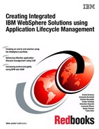
Business events can be used to detect various situations (that is, conditions, such as possible fraud or a new opportunity) that require prompt action. It is common for any follow-up action resulting from such a business event to be a process. Although other patterns exist, this sense-and-respond pattern is quite common, which is why we selected it for our warranty application. This pattern is shown in Figure 4-5.

Figure 4-5 Common sense-and-respond pattern
4.1.3 WebSphere Operational Decision Manager
WebSphere Operational Decision Manager V8.0.1, the next generation of business rules technology, delivers comprehensive automation and governance of operational decisions that control the actions of critical business systems.
It enables organizations to:
•Automate, govern, and improve operational decision making across business processes and applications for better business outcomes.
•Make more profitable decisions with real-time detection of opportunities and risks.
•Implement changes easily, reliably, and securely to meet new market demands and policy requirements.
This section provides an overview of the components in the product and how each component works.
Figure 4-6 shows the components that make up WebSphere Operational Decision Manager V8.0.1.

Figure 4-6 WebSphere Operational Decision Manager v8.0.1
These components are described in more detail in the following sections.
The WebSphere Decision Server
The WebSphere Decision Server is the runtime component where business rules and event applications are installed and executed. Typically, the WebSphere Decision Server is hosted on a Java based application server, and is packaged with WebSphere Application Server. You can also install and run it on other application servers or without an application server, albeit with limited capabilities.
The WebSphere Decision Center
The WebSphere Decision Center is a repository that contains the source of the rules. As such, it provides the governance capabilities and interfaces that enable business users to work directly with rules. WebSphere Operational Decision Manager might be used without using WebSphere Decision Center. However, doing so means that business users will not be able to manage and change rules directly in the tool.
Both the WebSphere Decision Center business console and the enterprise console enable business users to manage rules directly in WebSphere Operational Decision Manager. Each console is summarized in the next two sections.
Decision Center business console
This console provides a socially aware, web-based interface that enables business users to author, edit, organize, and search for rules in a collaborative environment. It is meant to coexist with the enterprise console, and offers the following features:
•Simplified navigation to quickly access the projects and elements you want to work on.
•Simplified editing of action rules and decision tables.
•You can see what changes have been made to projects of interest to you.
•You can see and post comments about recent changes made by other users, and you can attach files to these posts.
•Simplified search, available from a search box.
•Take snapshots of the current state of a project or its state at the time of a previous change.
|
Note: The term snapshot is used in the business console and corresponds to the term baselines in the enterprise console.
|
The WebSphere Decision Center enterprise console
This console is more sophisticated than the business console because it provides support for users who are involved with the day-to-day management and testing of rules, such as:
•Managing branches
•Project settings
•Deployment, security, and repository administration
•Creating queries
•Project reports and rule analysis
•Testing and simulation
•Creating templates, variable sets, functions, technical rules, and resources
The WebSphere Decision Center Rule Designer and Event Designer
The WebSphere Decision Center Rule Designer and Event Designer are the development environments for rule and event applications. The following sections summarize each tool and describe the main activities that are required to make and deploy a project using each tool.
Rule Designer
The Rule Designer is an Eclipse-based integrated development environment (IDE) for developing business rule applications. It is used by a rules developer who has Java development experience and business rule development experience.
The highest level organizational unit in the Rule Designer is a Rule Project, which consists of:
•An eXecutable Object Model (XOM) that represents the basic data structures upon which rules will be created.
•A Business Object Model (BOM) that maps the business vocabulary to the XOM.
•Rules that exist in one of the following forms:
– Business action language (BAL) rules, which are formatted as IF - THEN statements and are constructed using the vocabulary described in the BOM.
– Decision tables, which consist of one or more input columns and one or more action columns. Typically, these are used instead of BAL rules when there are large numbers of rules that are similar in structure and only vary based on the parameters.
– A decision tree of the rules that have built-in decision branches for dealing with more complex decisions than can be easily represented by a decision table.
•Ruleflows confirm the order in which rules must execute, and they might contain branching logic. There must be at least one ruleflow in a project (for example, the main ruleflow) because this is the entry point for rule execution.
After these items are developed, the Rule Project needs to be deployed. First, a RuleApp needs to be created that references the Rule Projects that need to be deployed. Then, the RuleApp is deployed to the WebSphere Decision Server run time.
Event Designer
The Event Designer is an Eclipse-based IDE for developing situational awareness applications. It is used by an event developer who has Java development experience and complex event processing experience.
The highest level organizational unit in the Event Designer is an Event Project that consists of:
•Event: A message that is to be processed and can come from many sources, such as a database, a file system, a JMS queue, or a web service.
•Event objects: Describe the data that is associated with the event. The event object is used to populate data inside a business object.
•Business objects: Temporary objects that are created at the time of an event to evaluate whether that event matches any event rules. Business objects can be made persistent, thus enabling rules to correlate events that happen over periods of time.
•Event rule: These are IF - THEN statements written in BAL and based on the vocabulary described in the business objects. Event rules enable patterns of events to be matched.
•Action: An outgoing message that can be triggered upon the success of an event rule. It can send a message to many different channels, such as a database, a file, a JMS queue, or a web service.
•Action object: Describes the data inside the business objects that are associated with an event.
4.1.4 Overview of business rules
Business rules can be represented in many forms, such as in a programming language or in company policy documents (in written form). When derived from written forms, business rules can be centralized and automated, which allows them to be read and understood by someone without having computer programming knowledge or experience. WebSphere Operational Decision Manager combines these approaches to allow business users to create rules in structured English (or for that matter, in any other human-readable language that can be represented in the Unicode Transformation Formats (UTF) character set), and then to deploy them so that they can be executed automatically. The following sections explain how to author and deploy business rules.
Building a Business Rule Project
Rule authoring is performed in the Rule Designer. It consists of a series of sequential steps described as follows:
Create a Java project with an XOM
The XOM is the base representation of the data structure that will govern the rules. For example, if a company is writing rules to process service claims, a data structure representing a service claim is needed. This data structure can be represented with one of the following:
•Java classes
•XML schema
For the service claim application, the XOM that is using Java classes is created using the steps below. After launching the Rule Designer, switch to the Java perspective by selecting it in the upper right corner of the Rule Designer, as shown in Figure 4-7.
Figure 4-7 Switching to the Java perspective in the Rule Designer
Next, a Java project for holding your Java classes needs to be created:
1. Select File → New → Java Project from the toolbar.
2. Name your project ServiceClaimsXOM, and then click Finish.
3. To create a Java class, select File → New → Class.
4. Complete the dialog box for the class description, as shown in Figure 4-8 on page 58, and click Finish.
Figure 4-8 Creating a Java Class for the executable object model
5. Create the private fields for the class, as shown in the top part of Figure 4-9.

Figure 4-9 Editing the Java class for the executable object model
6. The get and set methods for each field can be typed in directly, or you can generate them using the Source → Generate Getters and Setters option.
Your Java project now contains the XOM.
Create a Rule Project with a BOM
Next, a BOM is created. The BOM is the human-readable form of the XOM that is used to write rules. BOM is automatically constructed from the XOM when you create the Rule Project. Switch to the Rule perspective, as shown in Figure 4-10 on page 59.
Figure 4-10 Switching to the Rule perspective in Rule Designer
To create a Rule Project with a BOM:
1. Select File → New → Rule Project from the toolbar.
2. Select the Rule Project with a BOM option and click Next.
3. Name the project ServiceClaimsRules and click Next.
4. In the New Rule Project dialog, select the ServiceClaimsXOM project that was created in “Create a Java project with an XOM” on page 57, and click Finish when done, as shown in Figure 4-11.
Figure 4-11 Attaching the executable object model to a Rule Project
The Rule Project containing the BOM is created.
To understand where you are in the process of creating a functioning Rule Project, you can switch to the tabbed pane at the bottom of Rule Designer, labeled Rule Project Map. This shows a roadmap that indicates which elements in the Rule Project have been created and which ones remain. The diagram will look similar to the one shown in Figure 4-12 on page 60.
|
Tip: The Rule Project must be selected in the Rule Explorer pane for the Rule Project Map to be visible.
|
Figure 4-12 Overview of the steps involved in creating a Rule Project
Notice that there are numbers in parentheses next to some items, indicating how many of these elements have been completed. So far, we have imported XOM and created the BOM.
Define ruleset parameters
Before any rules can be written, the rule inputs and outputs need to be defined first:
1. Click Define parameters in the Rule Project Map window at the bottom of the Rule Designer.
2. Complete the parameters as shown in Figure 4-13.
Figure 4-13 Defining input and output parameters for a Rule Project
With the parameters defined as shown in Figure 4-13, the Ruleset Parameters are complete. Notice that the parameter is IN/OUT (means input and output parameter) and that the data type of the ruleset is the XOM that was created in the previous section. The parameter is populated according to the rule that will be created in “Create a rule” on page 61.
Create a rule
Now it is time to create rules. To create a simple IF - THEN rule:
1. Select File → New → Action Rule.
2. Name your rule partCostStatus and click Finish.
3. Create the rule as shown in Figure 4-14.

Figure 4-14 The service claim part cost rule
4. Press Ctrl+S to save the rule.
In Figure 4-14, the rule sets the action of the service claim to Attention status if the serial number starts with the letter S; otherwise, the action is set to Proceed. The print function was enabled for debugging purposes to ensure that the rule executes correctly.
Rule execution
Before a rule can be executed, the WebSphere Decision Server must be running, and the rules must be deployed. It is not possible to deploy a Rule Project directly; instead, a RuleApp project must be created that references one or more Rule Projects, and you deploy it. After the RuleApp is deployed, test it to ensure that it functions as intended.
Rule deployment
To deploy a Rule Project:
1. Start the WebSphere Decision Server by clicking Start the server of the ODMSample8010 profile that is configured on WebSphere Application Server v8.0. (The first time this is done, it takes a few minutes for the server profile to be created.)
2. Select File → New → Project from the toolbar, and then select RuleApp Project to create a new RuleApp.
3. Name the project ServiceClaimsRuleApp and click Next.
4. Click Add, select ServiceClaimsRules, click OK, and click Next when done.
5. Click Finish to create your RuleApp project, which references the Rule project and is now ready to be deployed on the server.
6. Ensure that the WebSphere Decision Server has started by checking its status in the Command Prompt window that opened when the server was launched.
7. In the Rule Explorer view, right-click ServiceClaimsRuleApp and choose RuleApp → Deploy, as shown in Figure 4-15 on page 62.

Figure 4-15 Creating a new RuleApp in Rule Designer
8. Click Next when asked about the RuleApp version, as this step is not important at this stage.
9. Enter the details for your WebSphere Decision Server. Typically, the default values are as follows:
– URL: http://localhost:9080/res
– Login: resAdmin
– Password: resAdmin
10. Click Finish to initiate the deployment.
If the RuleApp deploys successfully, the Console tab in Rule Designer will look like Figure 4-16.

Figure 4-16 Rule Designer console showing successful deployment of a RuleApp
For security reasons, the deployment process may be different in a production environment. For details, see the link provided in the note below.
|
Note: For guidance about how to deploy business rules, see Deploying business rules at:
|
Rule testing
Now, test the rule that was just deployed:
1. Select Run → Run Configurations from the Rule Designer toolbar.
2. Click ServiceClaimsRules under Rule Project, and select the Parameters & Arguments tab.
3. Click ruleData and press Edit Value.
4. Edit the parameter value so that it appears as shown in Figure 4-17.

Figure 4-17 Creating a test object in the Rule Designer
5. Click OK, and then click Run to test your rule.
The rule will execute, and if it completes successfully, your Console tab in Rule Designer displays the Need Financial Manager attention message. This is the result of the debug statement that indicates the serial number that is given needs a Financial Manager’s attention.
|
Note: The Business Rule project is created and it is assumed that you share the created projects in Rational Team Concert. Visit Appendix A, “Integrating the Eclipse environment with IBM Rational Collaborative Lifecycle Management” on page 223.
|
4.1.5 Overview of event rules
Event rules are similar in many ways to the business rules that are described in 4.1.4, “Overview of business rules” on page 56. The key difference between them is that event rules always have a time component, which can be phrases such as occurred within the last week or did not occur within the last 2 hours.
Table 4-1 on page 64 shows the various artifacts that make up the service claim project.
Table 4-1 Artifacts of the Event Rule Project
|
Name
|
Type
|
Description
|
|
EventReceived
|
Event
|
The incoming event received from a web service, which indicates a single service claim has been made.
|
|
EventReceivedObject
|
Event object
|
A description of the data in the EventReceived event.
|
|
ServiceClaimsBusinessObject
|
Business object
|
An object that the event object data copies and enriches when the event rule is evaluated.
|
|
ServiceClaimsHistoryBusinessObject
|
Business object
|
An object that accumulates historical events for users to correlate over time.
|
|
StartServiceClaimsEventInBPM
|
Action
|
The action generated by importing the Web Services Description Language (WSDL) of the BPM process, which starts the service claim process.
|
|
StartServiceClaimsEventInBPMRequest
|
Action object
|
A description of the data associated with the StartServiceClaimsEventInBPM action that will be sent to the process.
|
|
MultipleServiceClaimsEvents
|
Event rule
|
An event rule that detects a number of claims for the same serial number, if the service claims are processes in quick succession.
|
Building an Event Project
The Event Designer is a component of the WebSphere Decision Server. The Event Designer supports the definition of the metadata layer required for business event processing (BEP). The Event Designer can be used to create all of the building blocks for the application, including events, business objects, actions, and event rules.
This section highlights the sequential steps for creating executable rules using the Event Designer.
Create an Event Project
The Event Project for the sample service claim application is tied to the business process described in 4.2, “Managing business processes with Business Process Manager” on page 80. This business process defines a web service interface that is used by our Event Project.
|
Note: It is important to save any item that is created whenever it is changed. The project will not synchronize until a save is done, and if you attempt one without first saving your work, many errors might result.
|
To create a new Event Project based on an existing web service:
1. Select File → New → Event Project from the toolbar.
2. Name your project ServiceClaimsEvents, and click Finish.
|
Note: You will receive an error stating that “At least one field must have a definition.” You will learn how to resolve this error in “Map the Event object to the Business object” on page 69.
|
Since Operational Decision Management and Business Process Management are tightly coupled, creating the business process needs to be done in parallel with creating the rules, so that the WSDL can be generated from the process to import into an event rule. Import the WSDL file for the web service that will invoke the business process when multiple service claims are detected:
1. Right-click the newly created ServiceClaimsEvents and select Import.
2. In the import dialog, expand Event Designer and select WSDL into Event project.
3. Click Next and enter the following address to specify where to import the WSDL from:
Your dialog will be similar to that shown in Figure 4-18.

Figure 4-18 Importing a WSDL into the Event Designer
4. Click Next, followed by Finish.
The Event project has now been created with some minimal artifacts that trigger the BPM process when the events match the defined pattern.
Create an Event
The event and the event object that describe the event data need to be defined:
1. Right-click ServiceClaimsEvents and select New → Event from the pop-up dialog.
2. Leave the next panel as Create a blank event and click Next.
3. Name the event EventReceived and click Next.
4. Select Simple Object Access Protocol (SOAP) as the Event Connection type and click Finish.
5. Click Save to create your event.
The Event object does not have a data model associated with it, so you need to define the Event object that will hold the event data:
1. Select EventReceived (new event), and on the right side of the Event editor in the Event Objects section, click Add.
2. Specify Add a new blank event object and click Next.
3. Name the event object EventReceivedObject and click Finish.
4. In the EventReceivedObject editor, go to the Fields section and click Add.
5. Specify a Field name of SerialNumber with type String.
6. Click Finish.
7. In the Fields section, click Add.
8. Specify a Field name of eventTime with type DateTime.
9. In the Fields section, click Add.
10. Specify a Field name of trackingNumber with type String.
11. Click Finish.
12. Click Save All.
The resulting Event object fields look similar to Figure 4-19.

Figure 4-19 Event object fields after they have been defined in the Event Designer
Create a business object
Business objects are representations of objects such as Customer, Product, or Order. The primary purpose of a business object is to hold the data that is evaluated by event rules at run time. The data that populates a business object does exist in the enterprise applications, but it typically does not exist in a single record or structure. The fields in a business object can be populated from various sources.
A business object, as defined to Decision server Events, is the ideal representation of the business object because it serves as a template for sharing data, containing a number of fields that can be populated from many different business applications across the enterprise. Each field includes the name and type of information and an optional definition for how to get a value, if none is supplied with the event.
Two business objects are created in the service claim project: one to hold the event data for the current event, and another to accumulate historical data so that it is possible to compare events over time:
1. Right-click ServiceClaimsEvents and select New → Business Object.
2. Enter the name ServiceClaimsHistoryBusinessObject and click Next.
3. Select the option Create an accumulating array that retains the values of fields from previous events and click Next.
4. Enter a maximum number of instances of 2 and click Next.
5. Select EventReceivedObject and click Finish.
6. Click Save.
Now create another business object that holds the data that will be passed to the outgoing web service that launches the process in response to the situation being detected:
1. Right-click ServiceClaimsEvents and issue New → Business Object.
2. Enter the name ServiceClaimsBusinessObject and click Next.
3. Leave the option Start with a blank business object selected and click Finish.
4. In the Overview tab of the newly created business object, in the Fields section, click Add.
5. Specify a Field name of SerialNumber and a Data type of String and click Finish.
6. In the Fields section of the newly created business object, click Add.
7. Specify a Field name of TimeDifference and a Data type of Integer and click Finish.
8. In the Fields section of the newly created business object, click Add.
9. Specify a Field name of LastEventTime and a Data type of DateTime.
10. In the Fields section of the newly created business object, click Add.
11. Specify a Field name of TrackingNumber and a Data type of String and click Finish.
12. Double-click the TimeDifference field to edit it, choose a definition type of Javascript, and complete the expression box as shown in Example 4-3.
Example 4-3 TimeDifference function
function timediff(f) {
var diff = f[1] - f[0];
return Math.floor(diff/1000);
}
timediff(ServiceClaimsHistoryBusinessObject.eventTime);
The Field definition will look similar to Figure 4-20 on page 68.
13. Click Save.

Figure 4-20 JavaScript for the TimeDifference field
14. Click the Overview tab to return to the list of fields.
15. Double-click the LastEventTime field to edit it, choose a definition type of Java script, and complete the expression box as shown in Example 4-4.
Example 4-4 LastEventTime function
function lastTime(f) {
return f[1];
}
lastTime(ServiceClaimsHistoryBusinessObject.eventTime);
The field definition will look similar to Figure 4-21 on page 69.
16. Click Save.

Figure 4-21 JavaScript for the LastEventTime field
The creation of the Business objects is now complete.
Map the Event object to the Business object
When your Event object was created, it contained errors because there was no Business object to populate. In the previous section, you created the Business objects, so now the fields in the Event object to the Business objects can be mapped:
1. Double-click EventReceivedObject.
2. In the Fields Constructors section in the Overview tab, select SerialNumber and click Remove.
3. In the Field Constructors section in the Overview pane, click Add.
4. Select the ServiceClaimsBusinessObject and click Finish.
5. In the Field section, double-click the SerialNumber.
6. Select a Definition Type of Field and select the Event object field SerialNumber.
7. Click Save.
The mapping of the Event object to the Business objects and your mapping will look similar to Figure 4-22.
Figure 4-22 Field constructors for the completed Business object
Map the Business object to the Action object
Just as it was necessary to map the input from an Event object to the Business object, it is necessary to map the output from a Business object to an Action object:
1. Double-click the Action Object StartServiceClaimsEventInBPMRequest.
2. Change Definition Type to Field for the fields:
• impl:SerialNumber
•impl:TimeBetweenEvents
•impl:TimeOfLastEvent
•impl:TrackingNumber
3. Select the Business Object ServiceClaimsBusinessObject and the Business Object field as in Figure 4-23.
4. Double-click the field impl:isDuplicate.
5. In the Definition section, select Parameter as the Definition Type.
6. Type the Parameter Name as isDuplicated.
7. Click Save.
The mapping of the Business object to the Event object is complete, and your mapping will look similar to Figure 4-23.

Figure 4-23 Completed Action object mappings
Create an Event rule
To make this a functioning event project, indicating a response to the situation being detected, is an event rule. Event rules are the conditions under which, based on a pattern of events, an action fires. To create an event rule:
1. Right-click ServiceClaimsEvents and select New → Event Rule.
2. Name the rule MultipleServiceClaimEvents and click Next.
3. Select the event eventReceived and click Next.
4. Select System Context and click Next.
Specify the context relationship as the serial number of the serviceClaimsBusinessObject and click Finish.
5. Before typing the rule create a new action template. Double-click the action StartServiceClaimEventInBPM.
6. Once the action is displayed, check the verbalization section on the right side of the window and update the action template to startServiceClaimEventInBPM with parameter {0,isDuplicated}. This provides the parameter to be sent when starting the BPM process.
7. Create the rule by typing in the content from Figure 4-24.
|
Tip: As you type the rule, you are presented with suggestions based on the object model. You can activate this list of options any time in the rule by pressing Ctrl+Space.
|

Figure 4-24 Event rule to detect multiple claims within a short time
8. Click Save.
The Event project is complete and is ready for testing. The next step is to deploy the Event project.
Event deployment
Deploy the event rule as follows:
1. Start the WebSphere Decision Server by clicking Start the server of the ODMSample8010 profile that is configured on WebSphere Application Server v8.0.
|
Note: The first time this is done, it takes a few minutes for the server profile to be created.
|
2. Switch to the Event perspective on the upper right corner.
3. Right-click ServiceClaimsEvents and click Deploy.
4. Select Deploy all assets and click Next.
5. Enter the credentials of your WebSphere Decision Server configuration. The credentials will display similar to those in Figure 4-25 on page 72.
Figure 4-25 Configuration dialog for the Event deployment server
6. Click Finish and wait for the deployment to terminate.
7. After receiving a message that the deployment is successful, click OK.
8. Check WSDL to ensure that the event project deployed correctly.
9. Open a web browser and go to the following address:
The browser displays a WSDL similar to the one in Figure 4-26 on page 73.
Figure 4-26 Event WSDL showing that the event run time can receive external events
There might be other environments, such as test or production, to which you want to deploy the same rule. In that case, the event run time for each environment needs to be defined. During the deployment of the rule, you can specify which event run time the rule will be deployed to.
|
Note: For guidance about defining event runtimes and deploying to event runtimes, see Defining an event runtime server connection at:
|
Event testing
WebSphere Operational Decision Manager has a simple, web-based testing interface to check that the event project is working. The testing interface is available using IBM Business Space. Other tools, such as SoapUI, can be used to test the event as well.
Set up Business Space
To set up Business Space, follow these steps:
1. Access Business Space by opening a browser and going to:
2. Enter the administrator user name and password and click Login.
3. Select Manage Spaces → Create Space.
4. Name the new space Event Testing and click Save.
5. Create a page for the space. Provide a name for the space, and leave the Create an empty page radio button selected. Click OK.
6. Click the Event Testing space you just created.
7. Click the Edit page link in the right corner.
8. Select Events in the drop-down list.

Figure 4-27 Event testing page
10. Click Save and click Finish Editing.
The Event testing widget enables you to send event data to the event run time. Select the event template for EventReceived and try entering different events. Each event triggers the action with a parameter. When you enter two events that are within an hour of each other, and for a service claim that contains the same serial number, action begins by assigning the parameter with a different value according to the rule.
This action is visible in the Business Events testing interface. Additionally, as the event action has been wired to the business process, you can open the Process Designer by selecting Start → All Programs → IBM → Process Designer → Process Designer v8.0, logging in with a valid user name and password, and going to the inspector view to confirm the new processes that have been launched.
|
Note: The Event Rule project is created, and it is assumed that you share the created project in Rational Team Concert. For details, see Appendix A, “Integrating the Eclipse environment with IBM Rational Collaborative Lifecycle Management” on page 223.
|
4.1.6 Business management of rules
The core business benefit of business rules and event rules is that they can be managed by business users. This requires a large cultural change for many organizations, and many in IT might resist giving the ability to make system changes directly to business users. To address these concerns, it is important to discuss how WebSphere Operational Decision Manager provides the ability for business users to manage rules in a controlled manner.
In this section, we describe the principles of the rule governance model. This model can be customized to provide the level of control wanted by an organization. This section includes the procedure for deploying a rule application so that it can be managed effectively.
Rule governance and promotion model
We define rule governance as the procedures and mechanisms that are put in place around rule maintenance. These procedures and mechanisms ensure that the rules are performed in a controllable manner. The core component of WebSphere Operational Decision Manager, which enforces rule governance, is the Decision Center by way of the rule repository. Every rule in this repository has a status (such as New, Defined, Tested, or Rejected), and each is defined by the organization building the rules. In addition, the organization defines roles that are authorized to interact with the rule management system, given the level of access control granted to each user. Using a combination of roles and statuses, it is possible to construct a state diagram that describes the rule governance model at a high level. An example model is shown in Figure 4-28 on page 76.
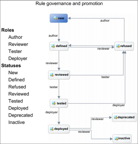
Figure 4-28 Example of a rule governance and promotion model
In Figure 4-28, you can see that each role has a defined set of transitions that it can perform from one status to another. In addition, it is possible to restrict each role in terms of capabilities. For example, certain authors might only have the ability to change certain groups of rules. It is also possible to define templates that restrict which parts of a rule can be modified.
Using Decision Center
Decision Center has a repository where rules are stored for business user interaction. It is the role of the business rule developer and event rule developer to synchronize, in the Decision Center, the rules that each developer designed to make them available to business users. After the rule or event projects have been deployed, a business user can log in to the Decision Center using a web interface to manage their rules.
There are two web interfaces:
•The Decision Center Enterprise console
As noted in “The WebSphere Decision Center” on page 54, the Decision Center Enterprise console is a more sophisticated environment than the WebSphere Decision console. The Decision Center Enterprise console provides business users with a significant level of control over rules. Although the Decision Center Enterprise console is not as powerful as the Rule Designer (in that the console hides the low-level implementation details), the Decision Center Enterprise console does support the full range of rule management activities.
•The Decision Center Business console
The Decision Center Business console is a simpler environment for business users who are primarily focused on maintaining rules and need to interact with others to track and discuss changes with other users.
Deployment to Decision Center
To examine the tools that are available to business users for rules management, export the Rule project and Event project to Decision Center.
|
Note: The procedure that follows is identical for both the Rule Designer and the Event Designer. If you want to access each of these in the Decision Center, carry out this procedure in each IDE separately. If you are already connected to Decision Center, we suggest that you disconnect. These instructions do not cover how to synchronize or delete an existing deployment.
|
To carry out this export to the Decision Center, follow these steps:
1. Open or switch to the IDE from which you will perform the deployment (either the Event Designer or the Rule Designer).
2. Right-click the project (either ServiceClaimsRules or ServiceClaimsEvents) to be deployed and select Decision Center → Connect.
|
Note: If the deployment is being done from within Rule Designer, the project that is deployable to Decision Center is the Rule Project, not the RuleApp or the Java Project.
|
3. Enter the connection details for the Decision Center. The address is the same as that when opening the Decision Center from the Start Menu. The user name is typically set to the default value of either admin or rtsAdmin and has a password that is the same as the user name. Your parameters will be similar to those shown in Figure 4-29.

Figure 4-29 Connection parameters for the Decision Center
|
Note: The machine name and port number for your installation might be different. If you cannot connect, confirm that your server is running, and then try changing the machine name to localhost (assuming the server is running locally) and check the port that it is running on. If port 9080 is already allocated when the server was installed, Port 9081 can be used.
|
4. Click Connect.
5. After the connection is established, click Finish.
|
Note: The next two steps might need to be done in reverse order, depending on how long you wait for the deployment to run. Read these steps before performing them.
|
6. Click No to avoid switching to the Synchronizing Perspective.
7. Click OK to accept the Synchronize Complete dialog.
Your project is now deployed in Decision Center.
For security reasons, the deployment described in “Deployment to Decision Center” on page 77 might not be feasible for a production environment. Refer to the link in the following note for further information.
|
Note: For guidance about how to deploy to offline server, see Deploying business rules at:
|
Business user interface
It is now possible to log in to either the Decision Center Enterprise console or the Decision Center Business console to view or modify the existing rules. The sections that follow show how to access each interface and perform simple navigation.
Decision Center Enterprise console
To open the Decision Center Enterprise console:
1. From the browser, enter the following:
2. Enter the user name and password and click Login.
|
Note: The user name is typically set to a default value of admin or rtsAdmin and has a password that is the same as the user name.
|
The home page of the Decision Center Enterprise console displays.
3. Select a project to access, as shown in Figure 4-30 on page 79.
Figure 4-30 Decision Center Enterprise console home page
You can now explore the project from a business user perspective. The Explore tab contains the project structure, and from this tab you can select rules and modify them. For example, to view the event rule that you created, follow these steps:
1. From the home page, set the Project in use to ServiceClaimsEvents.
2. Click the Explore tab.
3. Click the Rules folder.
4. Click MultipleServiceClaimEvents.
The rule displays, as shown in Figure 4-31.

Figure 4-31 A rule inside Decision Center Enterprise Console
You can explore the interface and edit the rule here. However, see the following Note.
|
Note: You should not edit the rule from Decision Center Enterprise Console. All rule editing should go through the requirements, change, and quality management processes for proper governance. For the rules to be synchronized, this task must be performed from Event Designer, which is beyond the scope of this section.
|
Decision Center Business console
To open the Decision Center Business console:
1. From the browser enter the following:
2. Enter the user name and password and click Login.
The What’s New tab on the home page of the Decision Center Business console is now visible.
|
Note: The user name is typically set to a default value of admin or rtsAdmin and has a password that is the same as the user name.
|
To view a rule, perform the following steps:
1. Click the Library tab.
2. Click the ServiceClaimsRules project.
3. Click the partCostStatus rule.
The rule you created displays as shown in Figure 4-32.

Figure 4-32 Rule in Decision Center Business console
This panel displays the rule in the left pane, with rule properties displayed in the right pane. Click the Timeline tab in the left pane to view the history and past versions of this rule. There have been no updates to the rule being viewed in Figure 4-32, however.
Click the Stream tab in the right pane to view all comments and other activities associated with this rule. You can add comments here as well. Other business users working on the same rule can use this feature to discuss and collaborate about this rule.
4.2 Managing business processes with Business Process Manager
BPM solutions enable an enterprise to choreograph processes and the process steps across disparate applications, people, and systems. Our service claim sample uses Business Process Manager V8.0.1 to realize the advanced, integration-related components of this comprehensive BPM platform. Service Claim Business Process is modeled with BPM.
This section of the chapter describes the following major components of the service claim sample:
•Service claim business process: Manages the core business process flow of the solution, and acts as the choreographer of process steps and activities.
•Integration with events and decision management: Manages the integration between process components and events, database, and decision management components.
|
Important: A basic knowledge of Business Process Manager is needed to fully understand this chapter.
|
4.2.1 Overview of BPM
The concept of process optimization was introduced during the Industrial Revolution through specialization. Thought leaders worked on streamlining their processes for producing goods, whether physical or natural, to get more products to market at a lower cost. This concept was adopted by many business leaders over the past decade because they needed help in managing the interactions between systems and humans. This discipline is BPM.
The key distinction between BPM and process optimization is the added focus of BPM on flexible and dynamic process design, process orchestration, and automation by the use of IT enablement. In addition to reduced cost through continued process improvement and automation, BPM provides the foundation for converged and agile businesses and IT responsiveness. Business leaders today look to BPM for guidance in getting products and services to market, better, faster, and cheaper than their competitors.
Figure 4-33 illustrates the core concepts of this discipline.

Figure 4-33 BPM drives business and IT alignment and responsiveness
BPM focuses on driving overall bottom-line success by integrating business verticals and optimizing core work (for example order-to-cash, integrated product development, and integrated supply chain). This focus helps to direct the deployment of resources throughout the organization into efficient processes that create customer value. This differentiates BPM from traditional (that is, compartmentalized) functional management disciplines.
Managed business process
A managed business process is a process in which stakeholders and process owners have both visibility into the process and the ability to modify it to produce better business outcomes. With process control, you can make informed decisions about how best to change the behavior of your process. These decisions might affect the process itself, or they might impact domains outside of the business.
As a manager, you regularly participate in decisions for change (see Figure 4-34). All management decisions, at any level in the organization, can be associated with one or more of the following domains: corporate strategy, business resources, and business processes.

Figure 4-34 Domains of change for a managed business process
Examples of corporate strategy decisions include entering new markets, discontinuing a product, and selling assets. You can imagine how these decisions might impact or lead to decisions in the business resource domain, such as hiring or training new human resources, outsourcing jobs, investing in technology, or making capital improvements to facilities. Decisions in the business process domain might include changing a decision threshold in a process flow to reduce the human workload (that is, lower the threshold) or reducing risk (raising the threshold) by changing the behavior of the process. Business process decisions might also include feedback to change the process by adding or removing activities.
4.2.2 Process automation, visibility, and control
Process automation, visibility, and control are compounding elements of the business impact realized by BPM (see Figure 4-35).

Figure 4-35 Elements of compounding values of a managed process
Process automation immediately accrues business value by increasing efficiency, reducing errors, eliminating process variation, and removing rework for human tasks. It is important to recognize, however, that automation is not the end goal of process improvement using BPM.
Process visibility allows you to see new aspects of your processes in tangible ways, and in some cases, in real time (when invoked). These capabilities provide insight into the performance of your processes, which can help identify areas for improvement through timely action. In addition, you will see a full, end-to-end view through process visibility.
Process control is what ultimately differentiates a managed process from an unmanaged one. Having control over your design-time and runtime business processes means you can engage the correct skills to address problems or effect change in a timely manner. By default, control demands full governance of your processes to ensure that all are operating consistently and in compliance with both internal and external policies and regulations.
4.2.3 Overview of Business Process Manager
Business Process Manager is a comprehensive and consumable BPM platform that provides visibility and management of your business processes. It allows IT to enable business users and managers to track their entire business operation on a single dashboard, receive alerts, and subsequently drill down to the lowest level of instance detail.
Figure 4-36 on page 84 depicts the major components of Business Process Manager.
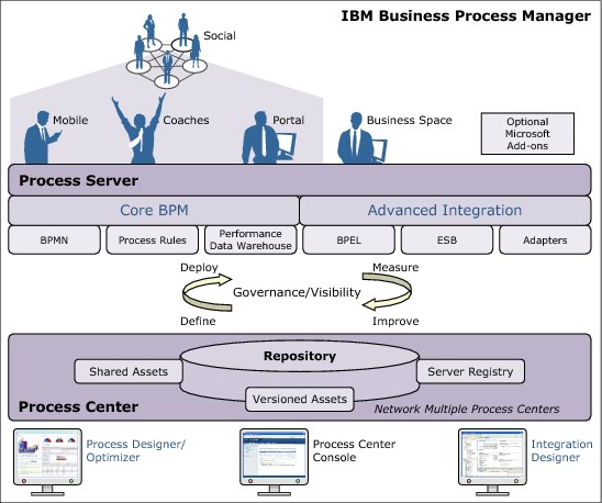
Figure 4-36 Major components of Business Process Manager
Next, we describe the available configurations in the Business Process Manager.
Business Process Manager configurations
Business Process Manager V8.0.1 is available in the configurations listed in Table 4-2.
Table 4-2 Business Process Manager configurations
|
Configuration
|
Phase
|
|
Advanced
|
Transformation
Complete set of BPM capabilities:
•Extended support for high-volume process automation
•Built-in service-oriented architecture (SOA) components for extensive enterprise-wide service integration and orchestration
|
|
Standard
|
Program
Configured for typical BPM projects:
•For multiproject improvement programs, with high business involvement
•Basic system integration support
•Rapid time-to-value and improved user productivity
|
|
Express
|
Project
Configured for a first BPM project:
•Rapid time-to-value and improved user productivity
•Low entry price
•Easy installation and configuration
|
Business Process Manager is a single BPM platform that combines human-centric and integration-centric capabilities into a unified product, which can be consumed per the capability requirements shown in Table 4-3.
Table 4-3 Business Process Manager configuration capabilities
|
Capability
|
Advanced
|
Standard
|
Express
|
|
WebSphere Lombardi Edition compatible execution
|
X
|
X
|
X
|
|
Process Designer (Business process model and notation, or BPMN)
|
X
|
X
|
X
|
|
Collaborative editing and immediate playback
|
X
|
X
|
X
|
|
Interactive process coach user interfaces
|
X
|
X
|
X
|
|
ILOG based process rules
|
X
|
X
|
X
|
|
IBM WebSphere Process Portal
|
X
|
X
|
X
|
|
Real-time monitoring and reporting
|
X
|
X
|
X
|
|
Performance analytics and optimizer
|
X
|
X
|
X
|
|
Business Performance Data Warehouse (BPM feature)
|
X
|
X
|
X
|
|
Process Center (BPM feature) and shared asset repository
|
X
|
X
|
X
|
|
Unlimited process authors and users
|
X
|
X
|
200 users and
3 authors |
|
High availability: clustering and unlimited cores
|
X
|
X
|
•4 cores production
•2 cores development
•No cluster
|
|
WebSphere Process Server compatible execution
|
X
|
|
|
|
IBM Integration Designer (business process execution language and SOA
|
X
|
|
|
|
Built-in enterprise service bus
|
X
|
|
|
|
Transaction support
|
X
|
|
|
|
Integration adapters
|
X
|
|
|
|
Flexible Business Space user interface
|
X
|
|
|
|
Advanced platform support (Linux on IBM System z®, IBM AIX®, Solaris)
|
X
|
X
|
|
Process Center
The Process Center is a feature of BPM. It is a runtime environment that includes a repository for all process models, services, and other assets that were created using the Process Designer or IBM Integration Designer, the IBM Business Process Manager authoring environments. It has a console with the tools that you need to maintain this asset repository.
From the Process Center console, administrators can:
•Install process applications that are ready for testing or production on the process servers in those environments.
•Manage running instances of process applications in configured environments.
•Grant appropriate authorization for users and groups to access the repository.
Administrators who do not actively work in the Designer view can use the Process Center console to provide a framework in which BPM analysts and developers can build their processes and underlying implementations.
Process Server
The Process Server is a BPM feature. It provides a single BPM runtime environment that can support a range of business processes, service orchestration, and integration capabilities. Because the Process Server is integrated with the Process Center, you can run your processes as you build them directly in the authoring environments.
When you are ready, you can install and run those same processes on the process servers in your runtime environments to test and prepare each for full deployment. The Business Performance Data Warehouse component collects and aggregates the process data from your processes that are running on the process servers. This enables you to test and refine your processes before formal deployment. You can use this data to improve your business processes.
Authoring environments
Business Process Manager Advanced offers two authoring environments:
•IBM Process Designer: Used to model business processes that involve human tasks.
•IBM Integration Designer: Used to build services that are self-contained or that invoke other existing services, such as web services, enterprise resource applications, or applications running in CICS and IBM IMS™.
Normally, a business analyst creates a new process in the Process Designer and defines an advanced integration service that the process uses. An integration developer creates that service in the Integration Designer and publishes it so the business analyst can use it to complete the process. The advantage of using these authoring environments is that both the business analyst and the integration developer can collaborate effectively using the Process Center repository, which reduces the time to build, test, and deploy new or revised business processes.
Process Designer
The Process Designer is available in all editions of Business Process Manager, and it has easy-to-use, graphics tools for creating process models, reports, and simple services. In addition, you can call a service that was created in the Integration Designer using an interface to access back-end systems or obtain customer data. In short, the Process Designer focuses on the business process, and the Integration Designer focuses on automated services to complement the business process.
Process applications developed in the Process Designer can, at any time, be run on the Process Center server or saved to a snapshot and deployed on the Process server. The same is true of services that are developed in the Integration Designer and associated with process applications.
Integration Designer
The Integration Designer is available in Business Process Manager Advanced Edition or as a stand-alone toolset. It is designed as a complete integration development environment for those building integrated applications. Integration developers use it to call applications on enterprise information systems that involve business processes across departments or enterprises. These developers can also invoke applications that are locally or remotely written, in various languages, and running various operating systems.
The Integration Designer tools are based on a service-oriented architecture. All services created with this tooling comply to leading, industry-wide standards. By using visual editors that abstract service components from their implementations, integration developers can assemble integrated applications without having a detailed knowledge of the underlying implementation of the components.
In the Integration Designer, components are assembled in modules. Imports and exports are used to share data between modules. Artifacts placed in a library can be shared among modules. Modules and libraries can be associated with a process application for use with the Process Center, and can be used as services by processes created in the Process Designer.
In such cases, processes can also be deployed with the process application. Alternatively, modules and libraries can be deployed directly to the test environment or to the Process Server. You can use mediation modules to create mediation flows, which you can deploy to the IBM WebSphere Enterprise Service Bus or to the Process Server.
Administration tools
Business Process Manager includes a set of administration tools to help you accomplish tasks, ranging from installing and managing snapshots to administering processes and working with the resources in your IT environment.
Command-line tools
The command-line tools, scripting interfaces, and programming interfaces enable you to administer your runtime environment:
•Command-line tools are simple programs that you run from an operating system command-line prompt to perform specific tasks. Using these tools, you can start and stop application servers, check server status, add or remove nodes, and so on.
•The WebSphere administrative (wsadmin) scripting program is a nongraphical command interpreter environment that enables you to run administrative options in a scripting language, and to submit scripting language programs for execution. It supports the same tasks as the administrative console, in addition to many of the Process Center console tasks. The wsadmin tool is intended for production environments and unattended operations.
•Administrative programming interfaces are a set of Java classes and methods under the Java Management Extensions (JMX) specification that provide support for administering Service Component Architecture (SCA) and business objects. Each programming interface includes a description of its purpose, an example that demonstrates how to use the interface or class, and references to the individual method descriptions.
The Process Center console
The Process Center console provides a convenient location for users to create and maintain high-level library items, such as process applications and toolkits. It helps to provide a framework in which BPM analysts and developers can build their processes and underlying implementations. In addition, the Process Center console provides tools for maintaining the repository, including setting up the appropriate authorization for users and groups.
You can access the Process Center console using a web browser:
The Process Admin console
The Process Admin console is used to administer the process servers in your environment, including the users and installed snapshots for each server. In addition, it provides tools to help you manage queues and caches.
The Process Admin console includes the Process Inspector, a tool to view and manage process instances for process applications that are running on a specific process server. You can access the Process Admin console using a web browser:
The Business Performance Admin console
The Business Performance Admin console includes tools for managing the Performance Data Warehouses in your environment. You can use this tool to manage server queues and monitor server performance. You can access the Business Performance Admin console through a web browser:
The WebSphere Application Server administrative console
The administrative console is used to administer applications, services, and other resources at a cell, node, server, or cluster scope. You can use the console with stand-alone servers and with deployment managers that manage all servers in a cell in a networked environment.
If you installed a stand-alone profile, you have a single node in its own administrative domain, known as a cell. Use the administrative console to manage applications, buses, servers, and resources within that administrative domain. Similarly, if you installed and configured a network deployment cell, you have a deployment manager node and one or more managed nodes in the same cell. Use the administrative console to manage applications, set up managed nodes in the cell, and monitor and control those nodes and their resources. You can access this console using a web browser:
Business Process Choreographer Explorer and Business Process Archive Explorer
Depending on your user role, you can do the following with the Business Process Choreographer Explorer and Business Process Archive Explorer:
•Use these client interfaces to manage business process execution language processes and human tasks created in IBM Integration Designer.
•Work with your assigned tasks.
•View completed business process execution language processes and human tasks that are in an archive database.
•Delete processes and tasks from the archive.
Business Space
Business Space is an integrated user experience for business users across the IBM portfolio of BPM products. Business Space provides a customizable and collaborative environment for you to monitor, review, and administer common business processes, such as human task flows, modeling, and performance indicators.
Business Space not only provides a single web-based point of access for the content. You can also use Business Space to combine the content in useful and interesting ways. These combinations can provide insight into your business and the capability to react to changes.
Business process rules manager
The business process rules manager is a web-based tool that assists the business analyst in browsing and modifying business rule values. The tool is an option on IBM Process Server that you can select to install at profile creation time or after installing the server.
4.2.4 Create a service claim sample
Now that the components and merits of Business Process Manager are discussed, we use it to create a business process for the service claim sample application, which is designed to process service claim exceptions. These exceptions are defined as either multiple claims coming in for the same item (that is, identified by its serial number) over a short period of time, or single claim.
In this example, a business analyst is assigned with creating the Service Claim Exception Process using the Process Designer. At the same time, an integration developer is tasked with creating the integration of the events and rules with the business process through the mediation layer.
To create the process:
1. Log in to the Process Designer.
2. Create a new process application by clicking the link to Create New Process App, indicated by the red arrow in Figure 4-37.
This process application acts as a container or package for business processes and related artifacts.

Figure 4-37 Create a new process application
3. Enter the name of the new application as Redbooks Service Claim Processes, provide an acronym, for example SCP, and enter a short description for your new process application.
4. Click the Open in Designer link to open the Service Claim Process process application in the Designer. Figure 4-38 shows this link with the red arrow.

Figure 4-38 Open the newly created process application
5. Create a new business process definition by selecting Processes → Business Process Definition (click the plus (+) sign to the right of Processes) as shown Figure 4-39.
To model a process in the Process Designer, create a business process definition, which is a reusable model of a process that defines what is common to all runtime instances of that process model.

Figure 4-39 Create a new business process definition
6. Name the new business process definition as Service Claim Exception Process, and click Finish to proceed (see Figure 4-40).

Figure 4-40 Name the new business process definition
7. The Process Designer generates your process diagram with the initial modeling constructs shown in Figure 4-41 on page 91.

Figure 4-41 Default process diagram for the new business process
A business process definition must contain a start event, an end event, at least one swimlane, and one or more activities, which is why the default process diagram contains these initial modeling constructs.
A swimlane is a visually separated row within a process flow diagram that groups all of the activities in the process that are performed by a particular combination of roles, resources, organization units, or locations. A business process definition needs to include a swimlane for each system (a system lane) or group of users who participate in a process (a participant lane).
You can designate any specific person or group to be responsible for the activities in a participant lane. Each lane that you create is assigned to the All Users participant group by default. You can use this default participant group for running and testing your business process definition in the Inspector. The All Users participant group includes all users who are members of the tw_allusers security group, which is a special security group that automatically includes all users in the system.
A system lane contains activities handled by a specific Process Center system. Each activity needs an implementation, which defines the activity and sets the properties for the task. During implementation, a developer creates a service or writes the JavaScript necessary to complete the activities in a system lane.
For the Service Claim Exception Process, create the following lanes:
– User (user who triggers the process)
– Technical support
– Financial manager
|
Note: For guidance about how to add and adjust swimlanes, see Deploying business rules at the following site:
http://www-01.ibm.com/support/knowledgecenter/SSFTBX_8.0.1/com.ibm.wbpm.wle.editor.doc/modeling/topic/adding_swim_lanes.html
|
8. When complete, your diagram looks like what is shown in Figure 4-42.
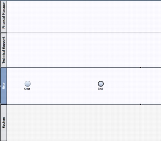
Figure 4-42 Service Claim Exception Process diagram
9. Next, model your business process, which entails the following high-level steps:
– Dragging modeling constructs from your palette onto the diagram area
– Specifying the details for a modeling construct by selecting it in your diagram and editing the properties in the Properties view.
Figure 4-43 on page 93 illustrates the activities to be added for Service Claim Exception Process. The activities in the diagram use the following color convention. It is not mandatory to do so, but any such convention used can be useful for readers to understand the workflow:
– Blue for Human task activities
– Red for Rule usage activities
– Green for Database activities
|
Note: For guidance about how to model processes, see Deploying business rules at:
|

Figure 4-43 Service Claim Exception Process diagram
Table 4-4 describes each of the activity steps of the Service Claim Exception Process. Use the information shown in this table to create the process diagram shown in Figure 4-43.
Each activity step in the business process needs to be assigned a task type and the implementing service. Table 4-4 lists all the task types and service types that are available in the Business Process Manager.
Table 4-4 Service Claim Exception Process tasks
|
Steps or activities
|
Description
|
Task type
|
Service type
|
|
Start event
|
Trigger for the process to start.
|
N/A
|
N/A
|
|
Retrieve information from database
|
Automated database lookup. Using the product serial number and tracking number, retrieve the information about the claimed product from the database.
|
System task
|
Integration service
|
|
Decision gateway
|
Split the execution path based on the parameter of the process input.
|
N/A
|
N/A
|
|
Technical support review
|
Technical support reviews the claim, along with the comments provided by the user.
|
User task
|
Human service
|
|
Decision gateway
|
Split the execution path based on the result of the Technical support review, that is, whether or not it is approved.
|
N/A
|
N/A
|
|
Claim action
|
Execute rules. Based on the serial number parameter, execute the rule to determine if the claim requires additional management review.
|
System Task
|
Decision Service
|
|
Decision gateway
|
Split the execution path based on the result of the previous step, in which the rule is executed.
|
N/A
|
N/A
|
|
Financial Manager Review
|
A financial claim manager must review any claim where the value (as determined by Claim Action) is high, for example if the action is to replace a high value part with a new one.
|
User task
|
Human service
|
|
Write claim status to the database
|
All claims (both approved and rejected) are written to an external database with the status of the claim.
|
System task
|
Integration service
|
4.2.5 Add a rule invocation for rules-related activities
|
Note: In this section, we create a Decision Service that uses the Business Rules application (ServiceClaimsRulesApp) described in 4.1.4, “Overview of business rules” on page 56. It is assumed that you have completed 4.1.4, “Overview of business rules” on page 56.
|
Our Service Claim Exception Process contains activities with a Decision service. This type of service is used when you want a decision or condition in a business rule to determine which process implementation is invoked.
Create a new Decision Service
To create a new Decision Service, follow these steps:
1. Open the Process Designer and navigate to the Designer view.
2. On the upper left corner of the window, click the plus (+) sign to the right of Decisions, and then select Decision Service, as shown in Figure 4-44.

Figure 4-44 Create a new Decision Service

Figure 4-45 Naming the new Decision Service
A Decision Service contains one or more of the following components:
•Business Action Language (BAL) Rule
You can use the rule editor in this component to author business rules using BAL. BAL is a declarative language that relates business concepts to business data and actions.
•JRules Decision Service
Business Process Manager integrates with IBM WebSphere ILOG JRules and the WebSphere Operational Decision Manager server using the JRules Decision Service component. You can use this rule component to connect to and implement rule applications that are available on a JRules Rule Execution Server.
•Decision table
The Decision table component is a rule table. Each row represents a Boolean condition that evaluates to true or false at run time. When a rule evaluates to true, the JavaScript expression that you provide as the rule action is started.
For the Service Claim Exception Process, we have chosen to use JRules Decision Service to create our Decision Service. This way, we can connect to the WebSphere Operational Decision Manager server and use the Business Rules application that we created in Section 4.1.4, “Overview of business rules” on page 56.
When building a Decision Service, follow these guidelines:
•Build your rule hierarchy so that rule conditions are ordered from most complex to least complex.
•Create a final condition that is a catch-all rule. This rule is necessary if you cannot guarantee that the variable you want to modify in a rule will be set before running the process that triggers your Decision Service.
•Consider encapsulating your rules in a single-function Decision Service, one that allows the service to be available to any other part of the process application that might need the same rule logic.
|
Note: For guidance about building a Decision Service, see Deploying business rules at:
|
Connect to the WebSphere Operational Decision Manager
To connect to the WebSphere Operational Decision Manager server:
1. First, the server must be added to the Process Designer. In order to do that follow the instructions in the link:
2. Double-click the Decision Service ClaimActionOnSerialNumber that you created in “Create a new Decision Service” on page 94.
3. After the service diagram opens, drag a JRules Decision Service from the palette onto your diagram and name it JRules Serial Number decision.
4. Select the arrow tool from the palette, link the start node to the newly created Decision Service, and then link that service to the end node.
5. With the JRules Decision Service component selected, click the Implementation option on the Properties tab.
6. In the Discovery section, select the Server from the drop-down box, SOAP port (if the Rule Execution Server is running on WebSphere Application Server), and the user name and password (in a secure connection). This connects you to a Rule Execution Server that contains the deployed rule applications (Rule Apps) that you want to use.
|
Tip: The SOAP port, user name, and password fields accept embedded JavaScript expressions, so you can use variables to provide those values.
|
7. Select the Implementation option in the Properties tab (see Figure 4-46) followed by the RulesServer from the server drop-down menu.

Figure 4-46 Connect to the WebSphere Operational Decision Manager
|
Note: If your Decision Server is not started, start the same server that you used to build the service. The link is included in Step 1.
|
8. Next, enter the user name and password that authenticates to your Decision Server instance, and click Connect (see Figure 4-47).

Figure 4-47 Discover the Rules Application to link with Decision Service
9. In the Rule section, select the Rule App that you want, followed by the version that you want to use. For the Service Claim Exception Process, use the ServiceClaimsRuleApp Rule App and the ServiceClaimsRules Ruleset, as shown in Figure 4-48.
|
Important: If a secure connection to the Rule Execution Server has not been established, the menu is not populated. In this case, manually enter the name and version of the Rule App and Ruleset that you want to use. The names must be accurate for the next step to work.
|

Figure 4-48 Discover the Rules Application to link with Decision Service
10. Click Generate Types.
11. In the Generating Types Wizard, make sure the Generate request/response wrapper types option is not selected (see Figure 4-49) before clicking Next.

Figure 4-49 Generate data types
12. Click Next through the remaining wizard windows until the type generation is complete, and then click Finish to accept default type generation (see Figure 4-50).

Figure 4-50 Generate data types
After verifying that your business objects have been created, examine them to check that they match with the parameters you defined when creating your rule project:
2. Specify the name of the input data type as input and the type as ruleData, and select the Has Default option.
3. Click Add Output, and specify the name of the output data type as output and the type as ruleData.
4. Click the Diagram tab (see Figure 4-51 on page 99).
5. Click back on the JRules Rule Service that you created.
6. Select the Data Mapping section (see Figure 4-51 on page 99) and enter a value of 0 for the Decision ID.
|
Note: The value for the Decision ID can be used for correlating business processes and decisions by passing the process instances ID as a parameter. This scenario does not use the Decision ID for any purpose, but it is a mandatory field. A value must be provided.
|
7. Map the tw.local.input input type to ruleData.
8. Map the tw.local.output output type to ruleData.

Figure 4-51 Input and output data mapping
|
Note: For guidance about adding a JRules Decision Service component to a service, see Adding a JRules Decision Service component to a service at:
|
Test the Decision Service
To test a rule component and the rules it contains, you can load the Decision Service with default data and then step through the activities in your business process diagram to see the generated process data as it interacts with your defined business rules. For example, if you set a breakpoint on an activity that has an associated Decision Service, you can make sure that the Decision Service is producing the data that you expect, and that it is not producing any error messages or exceptions.
To create a test process to execute the rules:
1. In the Process Designer, click the plus (+) sign next to Processes and choose to create a new BPD.
2. Name the business process diagram TestProductRule and then click Finish.
3. Click Decisions and drag the ClaimActionOnSerialNumber service into the system swimlane of the process diagram.
4. Connect the start node to the Decision Service using a connection arrow from the palette.
5. Connect the Decision Service to the end node in similar fashion to Step 4.
6. Click the Variables tab, click Add Input, and specify the name of the input data type as input and the type as ruleData.
7. Select the Has Default option and enter the value “S724” in the serialNumber field.
8. Click Add Output and specify the name of the output data type as output and the type as ruleData.
9. Click the Diagram tab and select the ClaimActionOnSerialNumber service.
10. Click the Data Mapping tab, set the input mapping to tw.local.input and the output mapping to tw.local.output.
11. Now your process and rule are ready to test. Click Play, and if asked to switch the view to the Inspector view, click Yes.
|
Note: You will see your process execute in the Inspector view. Wait until the process and Decision Service execute. The first time your process executes, all the service artifacts are compiled, so it might take 5 - 30 seconds to complete. Refresh the view every few seconds, and do not proceed until the status of your activity is complete and the process instance status is closed.
|
12. On the Execution State tab, select TestProductRule and then click the Variables tab to view the input and output parameters.
13. Select the input parameter to verify that the XML document contains the “S724” input parameter that you set.
14. Click the output parameter to verify that the action is set to Attention in the XML document.
Figure 4-14 on page 61 shows the logic of the rule that was written earlier in “Create a rule” on page 61. Try changing the input parameters for the test and observe the output change according to the logic.
|
Note: For more testing guidance, see Testing a Decision service at:
|
4.2.6 Add the user interface for human task activities
Users interact with, and participate in, a business process through user interfaces. Human services (human tasks) represent the actions that these users perform within the process, and coaches are the user interface for these services. In a Business Process Manager process, users interact with services and the service data using coaches. Coaches feature reusable coach views, which are reusable user interfaces that you can create and customize. Coach views consist of one or more other coach views, data bindings, layout information, and behavior.
To create a new human service and add the appropriate coaches to the user interface for this service:

Figure 4-52 Create a new human service
Figure 4-53 Name the human service
3. Add a coach, named ReviewClaims, to the Human Service diagram, as shown in Figure 4-54 on page 101.

Figure 4-54 Add the coach to the human service diagram
4. Add the UI controls from the right side palette to the coach panel (see Figure 4-55), and link the controls to input and output variables as needed.
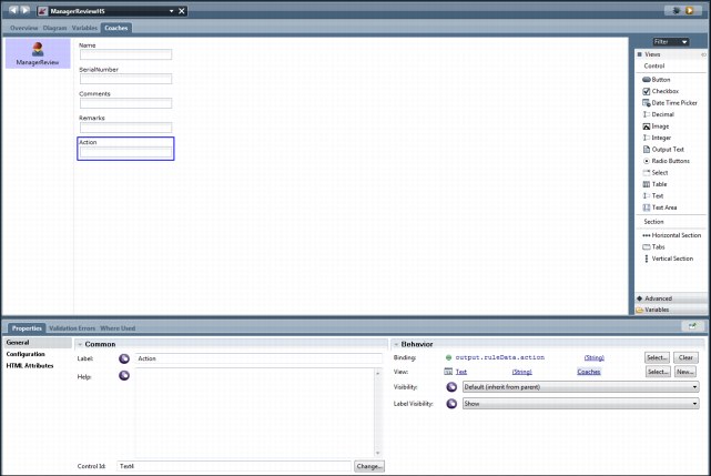
Figure 4-55 Add UI controls to the coach panel
After adding the UI controls, the ReviewClaims coach looks as shown in Figure 4-56 on page 102.

Figure 4-56 The ReviewClaims coach view
5. Navigate to the Warranty Exception Process, and link the Review Claims and Manager Review activities to the human service, as indicated in Figure 4-57 and in Figure 4-58.
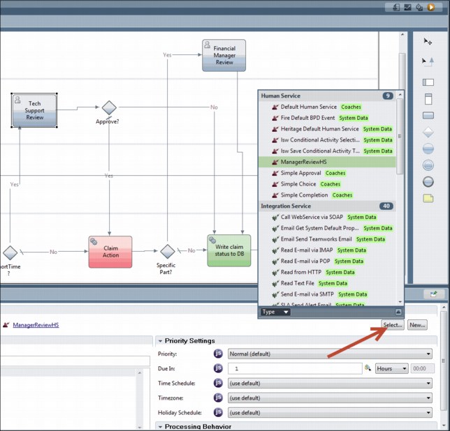
Figure 4-57 Link the human service to the business process diagram activities

Figure 4-58 Link the human service to the business process diagram activities
6. Modify the decision gateways in the flow to use the output from Step 5. This determines the processing paths.
Now we have the event-related activities of the business process diagram linked to the business rules, and the decision gateways are using the information to split the process execution path. We have integrated the business process with the business rules in a loosely coupled way, according to the pattern “Business process calling business rules” on page 52.
|
Note: For guidance about setting up a user interface for your human task, see Setting up a user interface for your human task at:
|
4.2.7 Create an Event Rule to trigger the business process
The business process that is defined is triggered as follows:
1. A web user interface sends a serial number through the WebSphere MQ queue.
2. The WebSphere MQ message is received by IBM Integration Broker flow, which converts the WebSphere MQ message into a web service invocation.
3. The Service Claim Exception Process is triggered when each WebSphere MQ message is received to raise an event by setting a parameter.
In this section, we define:
•The event that produces an action when the Service Claim Exception situation was detected by the WebSphere Operational Decision Manager
•How to add a message-based trigger to our Service Claim Exception Process through the use of Undercover Agents and other services is described.
Creating a new business object
Business objects define the business data that is used to describe the service and component contracts, in addition to the business data that the components manipulate. Basically, they represent the data that flows between services in an application. We need to define the data that will trigger the exception process.
To start, define a new business object called ServiceClaimEventType:
1. Open the Process Designer to the Designer perspective, then open the process application you have been working on.
2. Next to the Data field, click the plus (+) icon and select Business Object.
3. Name the Business Object ServiceClaimEventType.
4. Add the following fields to the ServiceClaimEventType:
– SerialNumber with type String
– TimeBetweenEvents with type Integer
– TimeOfLastEvent with type Date
– TrackingNumber with type String
– isDuplicate with type Boolean
– Name with type String
– Comments with type String
5. Save the business object.
Add a message-based trigger to the business process
To create a message-based trigger, we create the following general system services:
•Start Event
•Start Receiver
To begin:
1. Click the plus (+) sign next to the Implementation and select General System Service.

Figure 4-59 Start Event service diagram
3. Navigate to the Variables tab, click Add Input, name the variable ServiceClaimEvent, and change its type to ServiceClaimEventType.
4. Click Add Output, name the variable ServiceClaimEvent, and change its type to ServiceClaimEventType.
5. Navigate to the Diagram tab, and connect the start node directly to the end node using the arrow tool from the palette.
6. Save the activity.
7. Next to Implementation, click the plus (+) sign and select General System Service.
|
Important: This is the second general system service that you need to create. It is important not to confuse the two services, so pay close attention to the name of the service that you are working in as you proceed.
|

Figure 4-60 Start Receiver service diagram
9. Navigate to the Variables tab, click Add Input, name the variable ServiceClaimEvent, and change its type to ServiceClaimEventType.
10. For the input parameter, select the Has Default option.
11. Click Add Output, name the variable ServiceClaimEvent, and change its type to ServiceClaimEventType.
12. Navigate to the Diagram tab, drag an undercover agent (UCA) from the palette to the diagram, and name the UCA activityTrigger Start Agent.
13. Navigate to the Implementation tab, click New to create a new UCA, as indicated in Figure 4-61, and name it Start Agent, as shown.
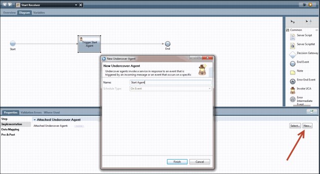
Figure 4-61 Creating a new undercover agent
|
Note: To learn about undercover agents and their use, see Understanding and using undercover agents at:
http://www-01.ibm.com/support/knowledgecenter/SSFPJS_8.0.1/com.ibm.wbpm.wle.editor.doc/modeling/topic/using_undercover_agents.html
|
14. Click Select and choose the Start Event service.
15. Click the Data Mapping tab and enter the value tw.local.ServiceClaimEvent.
16. On the diagram, connect the start node to the UCA Activity named Trigger Start Agent using the arrow tool on the palette.
17. Connect the Trigger Start Agent to the end node in the same way as it was done in Step 16.
18. Click the plus (+) sign next to Implementation, choose Web Service, and name the new Web Service StartServiceClaimEventWS.
19. In the Operations pane, click Add, and name the operation StartServiceClaimEventInBPM.
20. Click Select and choose the Start Receiver service.
Now that the implementation is complete, you can create a new web service to expose the Start Event of the Service Claim Exception Process as a callable web service using SOAP:
1. Attach the Start Receiver service to the newly created web service (as shown in Figure 4-62).
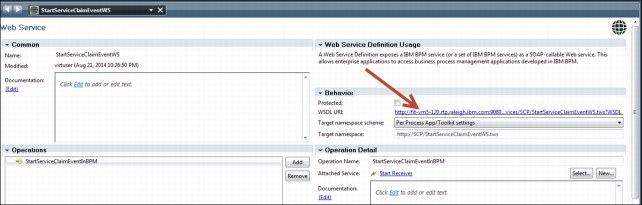
Figure 4-62 Attach the Start Receiver service to the new web service
2. In the Behavior pane, open the following address in a new browser window to display the WSDL:
3. Copy the address and save it in a text file.
4. Navigate to the Service Claim Exception Process and drag a Start Event into the diagram.
5. Name the event, Start Event, and place it at the start of the process, that is, before the Retrieve Information from database named activity.
6. Connect the Start Event to the next activity, that is, the Retrieve Information from database named activity (see Figure 4-63 on page 108).

Figure 4-63 Connect the Start Event
7. Select the Start Event activity.
8. In the Properties - Implementation pane, select Message Start Event from the Start Event Details drop-down menu, and attach the new UCA with this activity (see Figure 4-63).
4.2.8 Add database integration
An integration service enables your processes to communicate with an external system to retrieve, update, or insert data. Because you want each claim request data to be retrieved and claims data (from both approved and rejected claims) to be persisted into a database, you will create integration services called RetrieveInfo and Persist to perform the actions.
Before starting, however, you need to have a database defined and a data source that references that database on the Process Center WebSphere Application Server. The data source JNDI name is defined as “jdbc/serviceClaimDS” for this solution. The data table used is the SAW_REQUESTS table in the VIRTUSER schema, which is defined in Appendix C, “Database definitions” on page 239. This section describes the detailed steps to create the Persist action. You can use the same steps to create RetrieveInfo action:
1. Open Process Designer and then you are in the Design view.
2. Click the plus (+) sign next to Implementation and select Integration Service.
3. Name the Integration Service Persist.
4. In the diagram, drag a Server Scriptlet, a Server Script, and a Nested Service onto the diagram from left to right.
5. From the right side palette, drag and add the Server Scriptlet, Server Script, and Nested Service activities onto the diagram from left to right and join them in sequence.
6. Name the activities that you dragged in Step 5. Name them in the order that you dragged them (see Figure 4-64):
a. SQL statement definition
b. Set SQL parameters
c. SQL execute statement
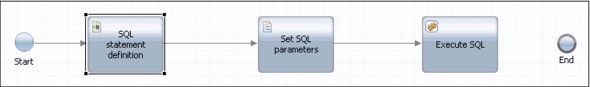
Figure 4-64 Adding activities to the service diagram
Each activity defines how an SQL statement with given parameters can be executed on Business Process Management process.
7. Click the plus (+) sign next to Data, select Business Object, and call the new Business Object TransactionType.
8. Add the following parameters to this type by clicking Add:
– RequestID Integer
– SerialNumber String
– StatusID Integer
– Remarks String
|
Note: If you are using your own schema and table, these types must match those in the table you will insert into.
|
9. Open the Persist service that you created, select the Variables tab, and add the following:
– An input variable named Transaction with type TransactionType
– A private variable named sqlStatement with type String
– A private variable named sqlParameters with type SQLParameter
10. Select the Is List option for sqlParameters, followed by the SQL statement definition.
11. Navigate to the Implementation tab and enter UPDATE VIRTUSER.SAW_REQUESTS SET REMARKS=?, STATUS_ID=? WHERE SERIAL_NUMBER=? and STATUS_ID=0, or an SQL update statement that matches your own schema. For binding, click Select, and select tw.local.sqlStatement.
12. Select Set SQL parameters.
13. Click the Implementation tab and copy in the code from Example 4-5, and shown in Figure 4-65 on page 110.
Example 4-5 SQL parameters
tw.local.sqlParameters = new tw.object.listOf.SQLParameter();
tw.local.sqlParameters[0] = new tw.object.SQLParameter();
tw.local.sqlParameters[0].value = tw.local.Transaction.remarks;
tw.local.sqlParameters[0].type = "VARCHAR";
tw.local.sqlParameters[1] = new tw.object.SQLParameter();
tw.local.sqlParameters[1].value = tw.local.Transaction.statusID;
tw.local.sqlParameters[1].type = "INTEGER";
tw.local.sqlParameters[2] = new tw.object.SQLParameter();
tw.local.sqlParameters[2].value = tw.local.Transaction.serialNumber;
tw.local.sqlParameters[2].type = "VARCHAR";

Figure 4-65 Setting values for the SQL statement using Server Script
14. Select ExecuteSQL.
15. Navigate to the Implementation tab, and, in attached service, click Select.
16. Choose SQL Execute Statement.
17. Navigate to the Data Mapping tab. Next to SQL, enter tw.local.sqlStatement, and next to parameters, clear the default box and enter tw.local.sqlParameters (see Figure 4-66 on page 111).
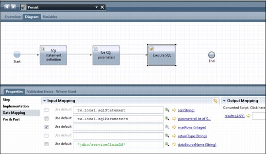
Figure 4-66 Adding data mapping for the SQL Execute Statement
18. Next to dataSourceName, enter the data source that you have configured in the WebSphere Application Server.
19. To create a simple test process, click the plus (+) sign next to processes, select Business Process Definition, name the process TestDatabase, and click Finish.
20. In the diagram, drag the Persist activity from the integration list into the System swimlane.
21. Connect the start node to the Persist activity with the arrow tool, and connect the Persist activity to the end node with the arrow tool.
22. Navigate to the Variables tab, click Add Input. Name the variable transaction and select the type TransactionType.
23. Click the Has Default option. Modify the default values to non-confidential values, for example:
– RequestID: 0
– SerialNumber: F547
– StatusID: 1
– Remarks “”
24. Navigate to the Data mapping tab, and for the input mapping, enter tw.local.Transaction.
25. Save the process.
26. Click the Play button, and if prompted, click Yes to switch views.
27. The data is now in the database. Use any database tool that you have available to verify that the data has been inserted into the database.
Apply the steps from section 4.2.8, “Add database integration” on page 108, from the first Step to Step 20. This will create the RetrieveInfo action and use select SERIAL_NUMBER, TRACKING_NUMBER, name, comments from SAW_REQUESTS where SERIAL_NUMBER=? and TRACKING_NUMBER=? SQL statement. The parameters for that activity will be similar to those in Example 4-6 on page 112.
Example 4-6 SQL parameters for the RetrieveInfo activity
tw.local.sqlParameters = new tw.object.listOf.SQLParameter();
tw.local.sqlParameters[0] = new tw.object.SQLParameter();
tw.local.sqlParameters[0].value = tw.local.inputRetInfo.serialNumber;
tw.local.sqlParameters[0].type = "VARCHAR";
tw.local.sqlParameters[1] = new tw.object.SQLParameter();
tw.local.sqlParameters[1].value = tw.local.inputRetInfo.transactionNumber;
tw.local.sqlParameters[1].type = "VARCHAR";
4.2.9 Deploy the process to Process Center
Once the process is saved on Process Designer, the current version of the process is directly deployed to Process Center. In order to keep the version tracking, you can get a snapshot of the current process from the Process Designer.
Mainly, production servers are offline servers, on which you cannot deploy the applications directly. In that case, refer to link in the note below for more information.
|
Note: For guidance about deploying processes to offline servers, see the following site:
|
..................Content has been hidden....................
You can't read the all page of ebook, please click here login for view all page.