
Chapter 8. Embedded Systems Analysis
Ronald van der Knijff
Contents
Introduction383
Definition and Operation384
Preserving Traces391
Data Collection397
Information Recovery413
Analysis and Interpretation of Results424
The Future430
Abbreviations431
References433
Introduction
When Joe checks his bank balance with a web browser on his mobile phone he immediately notices something is wrong. His balance is reduced to almost zero as a result of repeated daily cash withdrawals. Bewildered, he calls his bank to block his account. The bank investigates Joe's story and by correlating events from other customers, they find a suspicious point of sale terminal. The police officer involved seizes the point of sale terminal and sends it to the forensic laboratory for examination. At the forensic lab, fingerprint and DNA analysis is performed, assisted by a digital forensic expert to prevent any damage to the electronics and digital traces. Further analysis of the point of sale terminal reveals that it was maliciously manipulated with additional electronics to store and forward magnetic stripe data and entered PIN codes. The additional electronics uses a protected microcontroller to encrypt the customer data and a mobile phone with Wi-Fi for data transfer.
At the forensic laboratory some reference microcontrollers of the same type are used to develop a method to circumvent the read protection security. This method is then used to extract data from the program memory of the microcontroller found in the point of sale terminal. From the acquired memory data the cryptographic algorithm and the encryption key are reverse engineered. With this knowledge the encrypted data is decrypted resulting in a list of account numbers and PIN codes of compromised bank accounts. The flash memory from the seized mobile phone is also acquired. Although no SIM card is present in the mobile phone, some historical references to used SIM cards are found in the extracted data. With these references the telecom provider delivers subscription information leading to a suspect. The police find out that this suspect hired a car recently and when the navigation system of this car is examined a lot of waypoints close to other compromised point of sales terminals are found. The suspect is observed further and finally he and some other suspects are arrested. DNA material of one of the suspects matches with DNA found inside of the manipulated terminal. This evidence is presented in court by the prosecutor as strong evidence of attribution and is accepted by the judges.
This scenario is an example of cybercrime in which information technology is used both as the tool and target of a crime. Currently, the majority of digital forensics investigations involving embedded systems deal with more traditional criminal activities where information technology is used as an instrument without being an explicit target. For instance, homicide, drug dealing, terrorism, and child exploitation cases can have related digital evidence stored on mobile phones. However, as these systems become more sophisticated, there is a greater risk that they will be the target of attacks such as malicious code and data theft.
Embedded systems are probably the fastest growing source of forensic digital investigations. This is caused partly by technological developments where everything gets smaller, more portable, and wirelessly connected. The autonomous way in which embedded systems operate and leave digital traces, together with limited ways for users to access these traces also contributes to their forensic relevance.
This chapter starts with general information about how embedded systems work, followed by a description of methods and techniques for preserving, collecting, analyzing and interpreting the information they contain. It is important to note that some of the data acquisition methods described in this chapter can cause irreparable damage to the device. Even when experienced forensic examiners successfully acquire data, it may not be possible to return the device to its original working state. Given the number of abbreviations, the meaning of common terms is provided at the end of the chapter rather than expanding each one in the main text.
Definition and Operation
An embedded system is a special-purpose computer system designed to perform one or a few dedicated functions, often with real-time computing constraints. It is usually embedded as part of a complete device including hardware and mechanical parts (Wikipedia, 2008).
An embedded system can be defined as a computer system that is built in or “embedded” in a device of which it wholly or partially controls the functionality. The computer system and the device are indissolubly linked and one has no significance without the other (Parker, 1994).
These definitions are merely attempts to define the concept of embedded systems. An exact definition is impossible given the many manifestations of embedded systems and the rapid technological developments in this area. For the purposes of forensic examination, it is more practical to make a distinction between computer forensics for which dedicated hardware knowledge is required and computer forensics without the need for such specific knowledge. File system analysis for example, can be done without in-depth hardware knowledge, but to recover any additional information, the hardware characteristics of the storage medium need to be understood and they are mostly part of an embedded system (e.g., hard disk drive, tape unit, solid state disk).
Overview of Devices
The following overview, which was compiled in connection with the year 2000 problem, illustrates the diversity of embedded systems (de Backer, 1999).
Office systems
▪ Telephones (fixed and mobile)
▪ Computers (notebook, palmtop, electronic organizers, PDA, smart card, etc.)
▪ Fax machines
▪ Answering machines
▪ Copiers
Communication systems
▪ Data links (hubs, routers, bridges, etc.)
▪ Switch systems (X25, Frame Relay, etc.)
▪ Telephone exchanges
▪ Calling systems
▪ Satellite links
▪ Radio and TV links
Transport systems
▪ Global positioning systems (GPS)
▪ Embedded systems in cars, buses, trams, trains, aircraft, ships (airbags, navigation, cruise control, electronic locks, etc.)
▪ Energy supply (petrol, gas, electricity, etc.) (pipelines)
▪ Monitoring systems
▪ Systems controlling (air) traffic
▪ Parking meters
▪ Ticket machines (parking tickets, etc.)
▪ Systems controlling times of public transport (trains, trams, buses, etc.)
▪ Radar systems
▪ Systems for luggage handling
▪ Check-in systems
▪ Speed detectors
Household equipment
▪ Audio, video, and communication equipment
▪ Clocks
▪ Ovens, microwaves
▪ Heating systems
▪ Thermostats
▪ Central heating installations
▪ Alarm installations
Building management systems
▪ Systems for energy saving
▪ Emergency systems (UPS, no-break installations, diesel generators, etc.)
▪ Heating systems
▪ Cooling systems
▪ Lifts, escalators
▪ Systems controlling access
▪ Systems for burglar alarms
▪ Systems for fire safety
▪ Registration systems
▪ CCTV cameras
▪ Safes
▪ Door locks
Production systems
▪ Computer-aided manufacturing (CAM) systems
▪ Computer-aided design (CAD) systems
▪ Systems for (controlling) energy (production) (electricity, gas, water, etc.)
▪ Systems for registering time
▪ Systems for marking date and/or time (expiry dates, etc.)
▪ Clock-driven pumps, valves, meters, etc.
▪ Test, monitoring, and control equipment (temperature, pressure, etc.)
▪ Simulation equipment
▪ Machines
▪ Robots
▪ Weighing equipment
▪ Implements, tools
Banks
▪ Cash dispensers
▪ Payment machines (e.g., with check cards, etc.)
▪ (Credit) card systems
Medical systems
▪ Infusion pumps
▪ Cardiac equipment
▪ Pacemaker
▪ Laboratory equipment
▪ Monitoring equipment
▪ Equipment for imaging and processing (radiography, tomography, magnetic resonance, ultrasound, etc.)
▪ Support equipment for organ functions
▪ Ventilation equipment
▪ Anaesthetic equipment
▪ Surgical equipment
▪ Nursing equipment
▪ Sterilizing and disinfecting equipment
▪ Medical filing systems
More recently, efforts have been made to categorize a subset of embedded systems called small-scale digital devices for forensic purposes (Harrill & Mislan, 2007).
Relevant Components and Their Basic Operation
Figure 8.1 shows the basic model of a computer system. Communication between the central processing unit (CPU), the memory and the input/output components (I/O), flows via the address bus, the data bus, and the control lines. The CPU reads instructions (the embedded software) from the memory, taking actions based on the type of instructions it receives. This action can, for example, consist of calculations carried out by the CPU or of transport of data to or from peripheral devices. For embedded systems, the integration of components is often higher than for open computer systems. For example, there are electronic organizers with a single chip that contains the CPU, the various memories, and the drivers for keyboard and display.

A wide variety of CPU architectures are used in embedded systems: from classic 8-bit types (Z80, 6800, 8051) to more recent processor families (ARM, MIPS, ×86). In addition to the obvious input and output peripherals such as the keyboard and the display there are many sensors and actuators for measuring input and controlling the output of processes. Think, for example, of infrared transmission (IrDA), radio communication (Bluetooth, Wi-Fi), as well as sensors for measuring position, temperature, pressure, or movement and actuators for controlling a valve, inflating an airbag, or locking a door. The input and output facilities intended for test and repair purposes are also important for forensic applications as summarized later in this section and discussed more comprehensively in the section on boundary-scan/JTAG later in this chapter.
Memories
From a forensic examination perspective, memories are the most interesting embedded system components because they contain the most user related data. Memory refers to all semiconductor components of embedded systems that retain digital data. Besides memory, embedded systems can also contain other data storage media like hard drives or optical discs but these components can mostly be treated like open system components. For forensic examination of semiconductor memory it is important to know the main characteristics of different memory types.
Read Only Memory (ROM)
ROM is nonvolatile1 memory in which data are deposited during the production process and thereafter can only be read. ROM is used to store software and other static data. Embedded operating systems were often stored in ROM but this has changed since the introduction of flash memory.
Programmable ROM (PROM)
PROM is nonvolatile memory in which data are deposited not during the production process but at a later programming stage and thereafter can only be read. Variations on the basic design have resulted in different programming concepts with the following distinguished names.
Erasable PROM (EPROM)
EPROM is a PROM that can be erased as a whole with UV light and then reprogrammed (on the order of a hundred times).
Electrically Erasable PROM (EEPROM)
EEPROM is a PROM in which each individual byte can be erased electrically (up to a million times for modern types). In embedded systems, EEPROM is mainly used for nonvolatile storage of dynamic data (configuration preferences, transactions, etc.).
Flash
Flash is an EEPROM in which data can only be erased in blocks (up to a million times for modern types). Erasing results in a memory block that is filled completely with 1s. Flash memory comes in two flavors: NOR flash and NAND flash, named after the basic logical structures of these chips. Contrary to NAND flash, NOR flash can be read byte by byte in constant time. This property allows more efficient execution of code and is the reason why NOR flash is often used when the primary goal of the flash memory is to store firmware. 2 Parts of NOR flash that are not occupied by firmware are then used for user data storage. In NAND flash, blocks are divided further into pages, for example 32 or 64 per block. A page is usually a multiple of 512 bytes in size, to emulate 512 byte sector size commonly found in file systems on magnetic media. Additionally, a page has a number of so-called spare area bytes, generally used for storing metadata such as error-correcting codes (ECC). Modern NAND flash uses multiple levels of electrical charge to store more than one bit in each cell. This mechanism and the limited amount of erase cycles cause bit errors during normal device operation. Modern NAND flash relies on error-correcting codes, stored in the spare area bytes, to detect and correct these errors. If errors cannot be recovered, a block is marked bad and another block is used instead.
2Firmware is software that is embedded in a hardware device (like a mobile phone or a PDA). Because a processor needs byte-by-byte addressable memory for code execution, it is inefficient to store firmware in NAND flash. If program code is stored in NAND flash it needs to be completely transferred to RAM before a processor is able to execute the code.
Because of its high density of storage and fast access time, flash is emerging as a replacement for both ROM and EEPROM. NAND flash is the most used technology for the storage of multimedia data (music, photos, etc.) in embedded systems.
Such flash memory is often represented at the system level as an ATA disk with a FAT file system. The block structure has two important implications for forensic investigations. First, these systems are mostly built in such a way that deleted files are only marked in the FAT as deleted but can still be retrieved. After a disk formatting operation, the blocks might be physically erased, which makes recovery almost impossible. Second, different physical versions of one logical file can be present. This occurs when the size of the files is much smaller than the flash block size, which makes it more efficient to erase a block only if there is no more free space available in it. While there is free space, markings (available/unavailable) show which physical areas of memory are available. When there is no more free space in a block, only the active areas are copied to a free block and the old block is erased physically.
Random Access Memory (RAM)
RAM is volatile memory that can be written to as well as read. RAM can be divided into Dynamic RAM (DRAM needs to be refreshed periodically) and Static RAM (SRAM does not need to be refreshed). In embedded systems, RAM is used as working memory and in combination with a battery for nonvolatile storage of dynamic data.
Ferro Electric RAM (FeRAM)
FeRAM is a new, nonvolatile memory with the read and write characteristics of DRAM. For embedded systems, FeRAM has the potential in the future to replace all other types of memory as universal memory.
Table 8.1 summarizes the most important characteristics of the discussed memory types.
Boot Loaders
A boot loader is the first program that runs on a system causing the system to become fully functional. For a personal computer the BIOS chip contains the boot loader code. When an embedded system is powered on or being reset, the CPU jumps to a particular point in memory (the so-called reset vector). This is where the primary boot loader is located. The primary boot loader might execute preparation tasks before it jumps to a memory location where the secondary boot loader resides, which finally starts the application code or the operating system. Typical preparation tasks include initializing processor registers, and copying the secondary boot loader and sometimes an operating system from flash to RAM. Primary boot loaders often contain flash reprogramming routines to receive, check, and install upgrades of the secondary boot loader code for debugging and in field upgrading tasks. How boot loaders can be used for forensic data acquisition will be explained later.
Memory Management
Memory management refers to all methods used to store code and data in memory, keep track of their usage, and reclaim memory space when possible. At a low level this means a mapping between the physical chips and a logical address space via a memory map. At a higher level virtual address spaces with a memory management unit (MMU) might be used to give application programs the impression of contiguous working memory. In reality the memory may be physically fragmented into parts stored on different physical chips or other storage media. If a forensic examiner wants to know which physical memory locations of a device have been copied, in-depth knowledge of memory management is necessary as discussed in the section on data collection later in this chapter.
Flash File Systems
An increasing number of embedded systems that use flash memory for file storage emulate a block device with standard 512-byte sectors, and use a standard file system (like FAT) on top of it. This block device emulation needs to support reclaiming of blocks that contain deleted data3 (garbage collection). For reliable use of flash memory in a writable file system it is necessary to handle possible power loss between erase and subsequent write operations. Because erasing a block causes a block to deteriorate it is also desired to spread block erase operations as evenly as possible over the full range of physical blocks. The algorithms to do this are indicated as wear leveling and are often classified as sensitive intellectual property. Because blocks can become bad, block device emulation also needs to support bad block management. If the block device emulation and wear leveling techniques are not part of the file system they are part of a separate layer, called the flash translation layer. A more efficient use of flash memory is the use of a dedicated journaling flash file system (Jones, 2008). The implications of flash file systems on forensic data analysis are discussed in the section on file system recovery later in this chapter.
Boundary-scan
Boundary-scan is a testing method to test or debug electronic components. Components can be chips but also printed circuit boards (PCBs). A lot of modern embedded systems on the market today are boundary-scan enabled. Boundary-scan has been standardized under industry standard IEEE1149.1 but is more widely known as JTAG, the acronym of the founders, the Joint Test Action Group (IEEE–Standards Association, 2001). Figure 8.2 shows the basic principles of a JTAG enabled printed circuit board.
 |
| Figure 8.2 |
JTAG enabled printed circuit boards use a dedicated interface, called the JTAG test access port (TAP), designed to be daisy-chained between different chips on a board. This interface can be used to shift data into so-called boundary-scan registers. These registers are built into chips especially for testing purposes and are connected between chip I/O pins and their internal core logic. Depending on the state of the boundary-scan logic, the boundary-scan registers are invisible during normal operation of the device, connected to the I/O pins in external test mode, or connected to the internal core logic in internal test mode. With these operation modes it is possible to apply test vectors to a printed circuit board for testing connections between individual chips or control nonstandardized test and debugging functionality of internal processor cores. The use of boundary-scan for forensic data acquisition is covered in the section on boundary-scan/JTAG later in this chapter.
Preserving Traces
Once an embedded system has been recognized as relevant to an investigation, preservation steps must be taken to guarantee the original state of all evidence including the digital evidence. This preservation process can be quite challenging when dealing with embedded systems. It is not always apparent whether an embedded system is switched on or off, and inadvertently switching off a system might also destroy important digital evidence. It is also not trivial to determine to which other components a particular system is connected and what influences those components can have on the target device.
With the enormous amount of existing embedded systems, their wide technological diversity, and the extremely rapid development of new products, it is not realistic to have off-the-shelf forensic solutions for every possible embedded system exhibit. With limited forensic resources it seems a better strategy to spend research and development time on components that occur in the majority of systems and also have a high likelihood of containing relevant digital clues that can be linked to individuals. Before usage in an actual forensic case, the developed semifinished examination methods need to be adapted and tested to work on a similar reference device. Adequate preservation measures are very important in this approach because it might take some time after the seizure of an exhibit until the actual data collection takes place.
Nondigital Traces
In most actions related to preserving and collecting digital evidence, a form of physical contact will be established between the device and the examiners or their equipment. This contact might harm other forensic traces like fingerprints, DNA, or tool marks. Buttons, keyboards, and connectors for example are possible bearers for fingerprint traces and DNA. For high profile cases it is advisable to determine the optimal examination strategy with a team of forensic specialists from all relevant disciplines. Always try to record the initial state of the exhibits like the content of displays, the state of indicator lights, the position of switches, connections to other systems, or any visual damage.
Skimming is the illegal copying of magnetic stripe data and accessory security codes from debit or credit cards. A popular skimming method adds recording electronics to existing automated teller machines (ATM) or point of sale terminals (POS). Forensic examination of skimming equipment is preferably done with a team consisting of fingerprint, DNA, and Information and Communication Technology (ICT) experts. ICT experts carry out the disassembling of the electronics and DNA experts sample relevant parts for DNA material. Fingerprint experts know the most likely locations for fingerprint traces and prevent the other specialists from affecting these traces. DNA matches have been found based on material found on internal cable connectors. Skimming equipment often contains adhesive tape for connecting the rogue device to genuine parts of the ATM or POS terminal, which is a fruitful source for fingerprints. After DNA and fingerprint analysis, digitally stored data can be extracted and further analysis of the functionality can be done by ICT experts.
Live versus Dead Dilemmas
An intuitive approach for collecting digital evidence from an embedded system is to first copy all data from volatile memory, then switch the system off and copy all data from nonvolatile memories. This approach has some practical difficulties. There is generally no easy method to access the data in the volatile memory (Feldman et al., 2008). Furthermore, switching off a device might also change data in nonvolatile memories. Some systems, for example, start a garbage collection procedure on flash memory as part of their shut down sequence. This garbage collection might overwrite blocks of deleted data possibly containing relevant information from the past. Other systems do this as part of their boot process so power cycling must be kept to an absolute minimum.
A more practical approach is to keep the system running and conserve the system in such a way that the risks of evidence alteration are minimized. Contacting the manufacturer regarding technical details is recommended. A dedicated examination procedure can then be developed on a similar reference system before the exhibit is further examined. Manufacturers may not be forthcoming; even with a court order they sometimes seem to delay a request until a prosecutor loses interest or the criminal trial takes place. Nondisclosure requirements from manufacturers don't have to prevent manufacturers from sharing information because a nondisclosure can also be signed by other people from whom the judge decides that they need to know specific details during a criminal trial.
On 12 December 2007 part of the Netherlands suffered a power outage for almost 50 hours because an Apache helicopter from the Dutch air force hit a major power cable during a nighttime exercise. The aircraft's crew, who were using night vision goggles at the time of the accident, made an emergency landing without any injuries. A forensic quick response team immediately started investigating the case and embedded system specialists were asked to preserve and recover data from the Apache helicopter. With assistance from technical specialists from the Dutch air force the following sources of digital evidence were preserved:
▪ Data transfer cartridge (DTC), a memory module for storing flight related data like route, targets, and hazards that can be displayed onto a map during the flight
▪ Data downloaded from the Maintenance Data Recorder (MDR), a flight recorder with flight data, maintenance data, and audio with the last 30 minutes of cockpit communication
▪ Recordings from the Target Acquisition Designation System (TADS), a system primarily designed for usage in combination with weapon systems but also used for flight navigation
Data acquisition and analysis was done with both existing tools for this helicopter from manufacturer Boeing, and with specific forensic tools. Boeing generated a 170-page report from the MDC data with detailed technical information of the accident. TADS recording contained video images of the whole flight together with important flight data and audio recording of all internal and external communication. Because of Dutch law most of this information could be used only for the purpose of accident prevention and not for criminal or civil law (Onderzoeksraad Voor Veiligheid, 2009).
Maintain Power
To prevent the loss of any data stored in volatile memory, try to ascertain whether the system has a power source and take precautions to ensure that this power supply does not fail. In addition to a regular power supply, many embedded devices have a backup battery. Study the technical manual in an effort to establish the capacity of the backup battery. When the capacity is not known, take the precaution of replacing the backup battery. Try this out on an identical reference device to make sure that no data are lost. Never remove the normal power source and the backup battery at the same time.
Mobile phones for example have at least one main battery and sometimes a backup battery for powering the real time clock when the phone is switched off. Mobile phones can be recharged via their original power adapter or via several universal charging solutions.
It is not always immediately clear what role a battery plays in the working of an embedded system. During an investigation into an alarm mechanism used to detonate a bomb, the battery was removed, for the purpose of taking fingerprints, because there was no activity visible on the display. It later appeared that the complete alarm mechanism was supplied with power via this battery except the display, which was activated only after the display was connected to the main power circuit.
Don't Cause Security Barriers
Volatile data can contain information relating to security barriers previously passed by the user. Think of password entry, biometric authentication, or encrypted partitions. As long as the device is switched on, the security system usually does not influence the extraction of data, but after it is switched off the access procedure must be reenacted.
For GSM and UMTS phones, for example, a PIN code or a PUK code might be needed to access the chip card inside the phone when the phone is switched on, as discussed in the procedural portion of the section on data collection later in this chapter.
Isolate from Sensor Data and Network Connectivity
When initially preserving embedded systems, try to establish whether it has input or output components that can alter existing data. Global positioning devices for example are permanently reading positioning data from satellites. Navigation applications typically contain cyclical memory in which the last route taken is stored. When this information is relevant it is important not to move the system and to investigate whether it is possible to protect the cyclical memory against alteration. If it is not possible to prevent such alteration, then it will be necessary to examine the system on site.
Increasingly, embedded systems are being designed with networking capabilities. These network facilities might cause alteration of embedded system data from outside. A mobile phone that is switched on and connected to a network periodically exchanges data with that network. In addition to system data, individual personal data can change, for example, through incoming calls and incoming SMS messages. This may or may not be desirable depending on the situation. With a mobile phone, for example, it can be desirable to allow such data to be stored by the phone until all the transaction data related to the mobile phone has been acquired from the service provider.
Mobile phones, PDAs and other portable devices with valuable data might contain remote controllable self-destruct applications (DexMobile, 2008). These applications are meant to protect sensitive information after loss or theft but could also be used for antiforensic purposes. Unintended but exploitable self-destruct mechanisms exist that can be abused for antiforensics too (Leyden, 2001).
Forensic toolkits for mobile phone examination sometimes contain low-cost shielding solutions like special bags or shielded cabinets. It is important to realize that these solutions cause the battery to run down more quickly because the phone is using more power during network searching. When using such bags on a crime scene they need to be transferred to a protected area as quickly as possible. The most generic method for protecting live systems against wireless network originated data alteration is to store and examine them in a Faraday cage. A Faraday cage is an enclosure formed by conducting material that shields the interior from external electromagnetic radiation. All power and network connections in such a room are filtered to prevent external interference. Small Faraday cages exist with filtered power connections (LV Electronics, 2008). They can be used for preservation on crime scenes and powered during transport to bigger facilities for actual examination.
It is possible to think of situations in which it is inevitable that certain data in an embedded system will change. In such cases it is necessary to take such variations into account when assessing the integrity of the stored data. For instance, a mobile phone usually contains a real-time clock in which the data is changing continually. The value of this clock can be relevant (because most of the timestamps stored in the phone are taken from this clock) and certainly needs to be included in the report of forensic examination tools. The operative question is how to deal with this kind of dynamic data in the context of forensic integrity marks like MD5 values. Including such dynamic data in global device integrity calculations during acquisition is not desirable because it will cause the integrity mark to be different for each individual acquisition. This issue applies only to forensic acquisition of memory, since a global integrity mark is useful during subsequent analysis to check the overall integrity of digital evidence after using analysis tools on the data.
This is mainly an issue for logical extraction methods that use the regular operating system. The concern regarding dynamic data does not apply when acquiring physical memory via the JTAG interface because the normal opera- ting system is not running and thus cannot change any data.
Cleaning
Electronic devices that have been exposed to extreme conditions like fire or explosions need to be cleaned as soon as possible to preserve stored data and avoid further damage. The same holds for electronics that have been moisturized with water or blood, for example. Devices found in water or other fluids should be transported to a laboratory with the device submerged in the same fluid or in demineralized water and detached from batteries or other energy sources. Exposing these wet devices to air deteriorates the condition of the electronics much faster than when submerged. Blood in particular can be very damaging to printed circuit boards especially in combination with electrical power sources.
For cleaning printed circuit boards an ultrasonic cleaner and a mix of demineralized water with a nonionic surfactant like Triton X-100 is very effective.
Repair
Repair of an exhibit conflicts with the forensic principle of preserving the original state of the exhibit and is used only if no alternative methods exist or if there is no time or money for development of alternative examination methods.
During investigations of violent assaults, occasionally PDAs or mobile phones are encountered that have been damaged during the crime. Each digital clue can be relevant in such a case but there is not always enough time to wait for the development of dedicated low-level methods. In such cases attempts are made to repair an exhibit in order to use existing forensic tools that work only on fully functional devices.
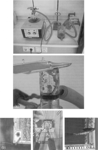
Since it is widely known that forensic tools exist for reading (U)SIM cards from mobile phones, as discussed in the next section of this chapter, suspects sometimes try to make their (U)SIM card unusable (by biting it, stamping on it, etc.). Often the (U)SIM cards no longer work but it is possible to repair them. First, the plastic cover is removed with a scalpel on the opposite side of the card to the contact surfaces. Second, the epoxy material protecting the chip is removed using an etching solution in a fume cupboard. The damage to the chip can then be assessed under a microscope. If the silicon surface has been torn or pulverized, further (partial) data recovery attempts are very labor-intensive with a very small chance of success. If the only damage is in the wires connecting the silicon and the contact surfaces, tiny needles (microprobes) are placed on the chip at the points where the connecting wires were originally attached. These probes are connected electronically to a smart-card reader through which the (U)SIM card can then be accessed. Figure 8.3 shows a number of examples of (U)SIM card repairs.
Data Collection
After an embedded system has been conserved and all potential evidence is preserved, an investigation needs to be carried out into what data it may contain and how this information can be accessed and read in a forensically sound manner. When it involves a commercial device, the preferred approach is to obtain the same type of device—an exemplar that can be compared with the exhibit. It can often be determined from the technical manual what kind of data can be present on a particular device and how this information can be protected, changed, and read out by the user. Additionally, technical documentation from the development phase or for maintenance and repair is valuable for retrieving information that is not of direct importance for the normal user. The data collection process can be divided into obtaining access and extracting data.
Getting Access
In order to collect data from an embedded system, some kind of communication channel must be established to give commands to the device and receive response data. User level communication channels like key input and display output, cable connections, infrared transmission, Bluetooth and Wi-Fi are used whenever possible. Otherwise system-level access channels need to be found and made ready for use. Many embedded systems have special access channels for test and debug purposes. JTAG is a standardized example of such a test and debug channel. Finding, enabling, and using communication channels will be discussed further in the physical data acquisition sections later in this chapter.
More challenging access tasks are the ones penetrating the security that is protecting stored data. Security barriers like a PDA power-on password or a smart card PIN code need to be passed when the normal, user level, communication channels of a device are used for data collection. These logical security measures are circumvented when data are read directly from the memories. Alternately, it may be necessary to circumvent a physical protection, for example by removing an epoxy layer covering a smart card chip. For some devices, it may be possible to reactivate a test circuit that has been disabled by the manufacturer by removing or replacing a resistor. A number of methods and techniques for getting access are presented here.
Procedural
In a number of cases gaining access is controlled via judicial procedures. This applies, for example, to get access to a (U)SIM smart card. (U)SIM ((Universal) Subscriber Identity Module) is a smart card with information about a UMTS or GSM subscriber stored electronically. Data in a (U)SIM can be protected with a PIN (Personal Identity Number). A PIN has four to eight digits, is requested after a phone is switched on, and is entered via the keypad of the phone. The number of attempts for entering a PIN is limited to three. If none of the attempts are successful the access to the protected data is blocked. This blockade can be lifted with a PUK (PIN Unblocking Key). A PUK has eight digits and is entered together with a newly chosen PIN. The number of attempts for entering a PUK is limited to 10. If none of these attempts are successful, most smart cards are configured to irreversibly block further PUK entry. In many countries PUKs can be obtained from the subscriber's network provider. For this the Integrated Circuit Card ID (ICCID) of the (U)SIM smart card is required plus, in most countries, judicial authorization. The ICCID is not protected with a PIN and can always be read out.
Procedures are also needed to access a mobile phone that is missing a (U)SIM card. Without a (U)SIM card, most mobile phones will not permit access to their normal input and output channels. This makes manual or logical data acquisitions problematic. Even if the phone permits access without a (U)SIM, it might contain data that is visible only after the particular (U)SIM card is inserted. Using another (U)SIM will likely not show the missing data and might even erase existing data in the phone memory. The phone evidently has a way to recognize the correct (U)SIM card, but a specially prepared (U)SIM can be used to let the phone “think” the missing (U)SIM is present. These programmable (U)SIMs are part of some forensic toolkits (Micro Systemation AB, 2006 and Netherlands Forensic Institute, 2006). Most phones use the IMSI4 and/or the ICCID to recognize a specific (U)SIM . This information can be found in call detail records of the network provider using the phone's IMEI5 as a search key and the appropriate judicial authorization. The identifiers needed to clone a (U)SIM card can also be recovered from the phone memory by first acquiring physical memory and then locating and decoding the required information.
Back-doors
Many systems for protecting access have a back-door built in deliberately with which the security can be circumvented. In some cases there is an extra password (a.k.a. master password) given in the technical documentation that always works. Some PDAs have a specific key combination that activates a system menu with an option to display portions of memory contents. The location of the password can be ascertained by studying these data on an exemplar device configured with a known password, after which the password of the exhibit itself can be retrieved. Mobile phones can contain a device password that must be entered as well as the (U)SIM PIN to use the phone. For some phones there are service sets generally used by repair centers that can be used to retrieve or circumvent these device passwords. Different approaches to finding back-doors are:
▪ Get in touch with the manufacturer.
▪ Search for documentation on the Internet. Searching on iPhone and passcode, for example, will quickly unveil a method to break the iPhone password protection (Zdziarski, 2008b).
▪ Trial and error on the basis of back-doors discovered previously. A combination of switching on a device and at the same time pressing certain keys often activates some service menu.
▪ Study communication interfaces. For many PDAs it is possible to make a complete backup on another exemplar of the same type. A complete backup means that all data, including the password, are transferred. The communication interface needed for the backup may be available to the user or may be for service purposes only. In the latter case a key combination is often needed to activate the port. Interface slots for extra hardware often offer possibilities for circumventing security.
▪ Reverse engineering by which the firmware is read and analyzed. A very useful tool for reverse engineering is the IDA Pro disassembler and debugger (Guilfanov, 2008). See the information recovery section later in this chapter for additional ways to use reverse engineering tools to examine data acquired from embedded systems.
Retrieving a back-door is time-consuming and often limited to one or just a few models. In addition there is the risk that a back-door will be removed in a product update as soon as this becomes generally known. For example, PDAs with older versions of Palm OS can be put in the debug mode via a graffiti keystroke after which an internal field in the Palm can be erased so that a password is no longer required. After this information became public Palm immediately announced that this fault in security would be rectified from Palm OS version 4.0 onward.
Measuring Memory
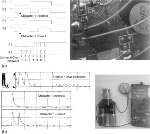
A naïve password verification algorithm runs roughly as follows: the correct password is stored in nonvolatile memory and the password given by a user is stored temporarily. After the input is concluded (e.g., with the Enter key), the CPU compares the entered password with the stored password and stops the moment there is a difference. The protected data is released only if there is no difference between the entered and stored passwords. If the location of the password in the nonvolatile memory is not yet known, keying in a correct password on the exemplar and measuring the data and address buses can reveal this location. A logic analyzer is used for this kind of measurement.
The logic analyzer is physically attached to the pins of the memory chip representing the address and data bus of the embedded system (see Figure 8.4). The power supply must never be interrupted when measuring RAM. Extra precautions are often required to guarantee this, such as milling a casing without damaging the battery compartment.
 |
| Figure 8.4 |
The address area of the password can be ascertained by studying these measurements after a number of experiments. Once the address area is known, the measurement can be adapted in such a way that only data related to these addresses is reproduced. With this arrangement the first character of an unknown password can be retrieved. By entering this first character during the subsequent measurement, the algorithm will run in the same way and report only after the comparison of the second character that the password entered is not correct. The second character is now known. The other characters of the password can be retrieved by repeating this procedure a number of times.
Memory Injection
It is not always possible to retrieve the password using the method just described; for example when the password is not directly written in the memory but is hashed or encrypted, or when the number of consecutive false entered passwords is hard limited or causes an increasing input delay. The location of the password can often be established by making more measurements with different passwords. In these cases the password can be overwritten with the data of a known password. 6 The memory data belonging to that known password can be read from the exemplar device. If the location of the password has been established with the logic analyzer, a pattern generator can be connected to the memory chip programmed in such a way that the data is changed at the addresses where the password is located, thus replacing an unknown password with one that is known. The disadvantage of this method is that data is entered into the memory of the exhibit and the password information is thus altered. After the investigation has been concluded, the memory can be restored to its original state. Some logic analyzers contain their own pattern generators and these can be utilized. The Netherlands Forensic Institute has developed the Memory Toolkit for carrying out memory measurements and memory injections as discussed later in this section.
6Instead of concentrating on the password, it may be possible to search for the password checking algorithm in the program memory and insert a variant that causes the password to always be assessed as correct. For this to work it must be possible to adapt the program memory (physical replacement with ROM or reprogramming with flash).
Correlation Measurements
All the aforementioned methods of accessing memory on embedded systems work only if the address bus and data bus can be accessed by the measuring equipment. In compact systems in particular, all the memory components are integrated with the CPU in a chip and covered with a layer of epoxy (one-chip types). When dealing with such one-chip types, precise measurement of CPU related signals (rather than memory measurements) offers a solution. When dealing with the password verification algorithm described earlier, it is clear that a certain time elapses before the CPU reports that the password is incorrect. The more correct characters there are, the longer the process of checking will take. By measuring the time that is needed for the verification of a password entered it is possible to ascertain how many characters of the password entered are correct. The procedure for retrieving the complete password is then as follows:
1. Try all possible, one-character-long passwords (0…9, A…Z, a…z, etc.), and with each entry measure the time taken for verification.
2. One of the measured time durations is significantly longer than the rest, the character that takes the longest time is the correct one (for example, Q).
3. Now repeat points 1 and 2, increasing the password to be tried by one character at a time, varying only the right-hand character and all the characters to the left of that are chosen as the characters found in step 2 (Q0…Q9, QA…QZ, Qa, …, Qz, etc.).
The problem with this method is finding measuring points with password-dependent time variations. When measurements are made digitally with a logic analyzer on one-chip type devices, the most favorable approach is to measure as many accessible points as possible on the printed circuit board in the neighborhood of the chip. The measurement data can be transferred to a computer system and analyzed to locate measuring points that vary only for correct entered characters. When a (digital) oscilloscope is used for measurements, the power consumption can also give useful measurement data (Mangard et al., 2007). Figure 8.4 shows examples of both measurement methods.
Brute Force
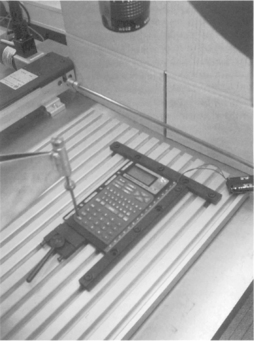
With the brute force method, a series of passwords (whether or not exhaustive) is entered into a system. When the order is chosen in such a way that the most likely passwords are tried first, this is known as password guessing. 7 In contrast to (U)SIMs and modern mobile operating systems, for example, a lot of devices have not limited the maximum number of consecutive incorrect attempts that can be made to enter a password. When dealing with embedded systems, users often select short, easy-to-guess passwords. The brute force method also has the great advantage that it is not usually destructive and can thus be tried first on an unknown system of which there is no other exemplar available. Some devices (e.g., BlackBerry, iPhone) will erase all data after a set number of incorrect password attempts. Depending on the type of system the password can be entered mechanically or electronically (see Figure 8.5 for a mechanic variant).
7The correlation method described here is also a form of brute force, not per password but per password character, which reduces the number of possibilities drastically.
For a password hash read from embedded system memory, it is also possible to use offline password guessing or brute force. With this method hashes are calculated on a fast computer system and then compared with the extracted hash until a match is found. The found password is not necessarily the same as the original one because different passwords might have similar hashes.
Manual Examination
A manual examination of embedded systems utilizes human computer interfaces like key input and display output, to extract as much data as possible. Reasons for choosing such a low-tech examination method include:
▪ In some cases, speed is more important than forensic soundness. If it is only important to know the value of the last trip counter of a car, it makes sense to switch on that car instead of spending a lot of time developing a forensically sound extraction procedure.
▪ With other methods it is not possible to extract certain evidence or to guarantee the integrity of certain data elements. Some mobile phones for example, have data cable connection points inside the battery compartment. Removing the battery to access these points may alter the date and time values of the phone. If these values are expected to be important they can be extracted via the user menu of the phone.
▪ The conversion of extracted data into information (decoding) is problematic. If no documentation is available on how specific data are formatted and all attempts to decode the data fail, the device itself might be a useful tool. In a mobile phone examination for example, data related to deleted voice dialing commands were found but it was not possible to play these voice tags with any available sound player. Through testing it was discovered how the phone coded the delete status of a voice tag and after flipping the deleted status data back to nondeleted, the voice tags could be played via the original phone.
The investigator needs to have the technical documentation for the system and needs to be experienced in manual examination of the target device. This will avoid data being unwittingly lost or affected. 8 All the operations need to be documented and it must be stated in the final report that the data have been extracted manually. Manual acquisition does not guarantee that all data are retrieved and also has the disadvantage of possible human (typographic) errors. For computer assisted manual examinations, forensic tools exist that use a camera and computer software for documenting screen contents during a manual examination (Fernico, 2007 and Project-a-Phone, 2007).
8When mobile phones are being examined manually, it regularly happens that important data are overlooked due to inexperience of the investigator. For example, the investigator consults the last telephone numbers dialled but is not aware of a key combination specific to that model, which can also reveal the date and time.
During an investigation related to the death of a baby, a digital fever thermometer was examined. The police wanted to know the last measured temperature. After contacting the manufacturer and conducting tests with a reference device it turned out that the last measured temperature could be displayed by holding down the power button for a few seconds after powering on the device.
Logical Data Acquisition
Logical data acquisition refers to data extraction techniques without direct access to raw memory data. Logical data acquisition often uses common, high-level protocols to extract information elements that can be interpreted by a user without additional decoding. Most forensic phone software use as one of their methods, for example, the Hayes command set9 to extract phone book entries, SMS messages, and call related data from mobile phones (Ayers et al., 2007). Some other popular protocols for logical data acquisition are SyncML, OBEX, IrMC, ActiveSync, Fbus, ISO7816-3. Another class of forensic logical data acquisition tools runs a kind of software agent on the exhibit, using the original operating system to transfer file system data to an examination host (Oxygen Software, 2008) or multimedia card (Me, 2008). Logical data acquisition methods do not generally capture deleted data.
9The Hayes command set, also referred to as AT commands, is a specific command-language used by most dialup modems. A lot of mobile phones and mobile data cards also use this command set.
During a forensic autopsy an artificial pacemaker was secured for forensic information analysis. An academic hospital was contacted and they had equipment to read the data from this pacemaker via a wireless interface. The extracted information contained around 10 pages of details like name and date of birth of the patient, timestamps of hospital service, technical parameters, and stored measurement details related to the heart function.
Commercial, nonforensic, backup, and synchronization tools that can be used for logical data acquisition are available for many embedded systems, including marine and handheld GPS (Global Positioning System) units. In contrast to navigation systems in vehicles, handheld GPS units generally store position data rather than complete routes. Three types of position data can be distinguished:
▪ Track-log: A FIFO (first in/first out) buffer in which the current position of the GPS unit is continuously stored as soon as this differs from the original position.
▪ Routes: The series of points from the track-log where the alteration in course took place. This information is stored on the initiative of the user.
▪ Waypoints: Autonomous positions kept by the user that can often be provided with a brief text (Home, Pub, etc.).
A standardized interface exists for getting live position data from GPS equipment (NMEA). This interface is not very useful for forensic acquisition but data formatted according to NMEA specifications can sometimes be found in volatile or nonvolatile memories of GPS enabled devices. Various software is available for reading post-mortem position data and visualizing it on a map (GPS Utility Ltd, 2008 and Forensic Navigation, 2008).
A vehicle electronic control unit (ECU) is another example of an embedded system that can be acquired logically. For vehicle systems that incorporate computer control, the assembly containing the microprocessor is called ECU. ECUs control vehicle functionality like antilock breaking, air bags, and seat-belt tensioners. ECUs get data from sensors measuring vehicle speed, wheel speed, deceleration, among others. They transmit control signals to actuators like valves, air bag igniters, and dashboard indicators. Within an ECU, nonvolatile data is saved in EEPROM or flash memory. This information usually includes diagnostic trouble codes (DTCs) and optional parametric crash data. Data obtained from one or more ECUs are often called black box data, and might be useful for forensic investigations. Connectors and connection protocols for vehicle diagnostics are highly standardized and a lot of commercial scanners exist. Most of these scanners can extract only the diagnostic error codes. Proprietary scanners are needed to extract manufacturer-specific data, which is often the most interesting from a forensic perspective (Ching-Yao, 2000 and Rossenbluth, 2001).
Airbag data from the ECU of a crashed car was extracted and decoded with a method performed by the airbag manufacturer. The data showed deceleration values in a short interval around the airbag deployment. The differences between consecutive measurements on milliseconds interval times were so big that they could not be caused by the heavy weight of a car. Further examination of the ECU unit revealed a broken fastening bolt causing not the car movement to be registered but the ECU movement. This made the data useless for the initial question about the speed of the car just before the crash.
Physical Data Acquisition
Physical data acquisition refers to data extraction techniques with direct access to real memory locations. This can be compared with bit-stream images of computer hard drives. Most built-in embedded system storage cannot be accessed with generic connection interfaces like ATA or SCSI for personal computers. The most generic connection interface for embedded system memories is the use of the physical connection points on the memory chips. Several chip package technologies exist (DIP, SIP, TSOP, PGA, LGA, BGA) and for each package technology a large number of variations are used in the number, the spacing, and the size of connection points. This diversity makes the use of physical connection points for forensic data acquisition expensive and impractical for generic use. Therefore, several less ideal methods of acquiring physical memory are commonly used.
Software Agents
Software agents are pieces of software running on the exhibit device, assisting with, or responsible for, the physical data acquisition. These agents run on the normal operating system of the device and use Application Programming Interface (API) calls for low-level memory access, or they use a dedicated operating system for data acquisition. For this approach to work, the system needs to be accessible and must allow the execution of custom software. The Symbian OS, for example, has a low-level API function called RRawDisk that enables direct disk access (Breeuwsma et al., 2007). On Windows CE-based devices a similar approach can be used to read data from RAM and flash memory using ActiveSync and remote API calls (Hengeveld, 2003). For iPhone and iTouch devices a commonly used examination method puts commands on the system partition to remotely login to the device and copy the user partition via Wi-Fi to an examination machine (Zdziarski, 2008a and Hoog, 2009).
Because most software agents run on the normal operating system, precautions are needed for locked files or other processes changing the target data. Software methods can also be used to acquire RAM data but because the agent itself also uses RAM space it potentially overwrites interesting evidence in unallocated RAM areas (Schatz, 2007).
Boot Loaders
As described earlier in this chapter boot loaders on embedded systems can contain functionality for direct access to memory locations. The interactive boot loader of a lot of HTC devices running Windows Mobile for example, can be activated by holding down the camera and power button and resetting the device. The boot loader's d2s command can be used on some devices to copy the contents of internal memory onto an inserted multimedia card or onto an examination system via the USB connector.
Instead of directly using the built-in boot loader functionality another approach uses the primary boot loader to transfer custom executable code to one of the writable device memories and to start executing that code. Embedded systems often have this flash loader functionality for in-field upgrading of firmware.
Additional boot loader functionality is widely used in the mobile phone world by both manufactures and hackers. Manufacturers use this method for debugging and repair and for in-field firmware upgrades. Apple, for example, distributes firmware upgrades for their iPhone and iPod devices via their iTunes software. iPhones can be switched into different upgrade modes; the most low-level one is used to update the boot loader itself and could also be used for forensic purposes. Hackers also use boot loader functionality to attack device security functions, installing custom firmware, or changing normal device behavior. 10 Flasher box is the common name for interface devices to connect mobile phones with computer systems for managing additional boot loader functionality. Flasher tools mostly contain a flasher box, control software, and a large number of cables to connect different phone models (GSM-Forum, 2008 and Multi-com, 2008). Great care should be taken when using these tools for forensic examinations. Besides memory acquisition functionality, these tools sometimes have other options that are devastating in a forensic context like writing or erasing memory, changing serial numbers, or adding functionality. Before usage on an exhibit, a flasher tool needs to be tested on a similar device: once thoroughly to check the functionality, and preferably before each individual examination to train the examiner in using only the forensically sound options of such a tool (Al-Zarouni, 2007).
10A very instructive open source project aimed at running Linux on iPhone hardware contains a custom developed boot loader that can be used to acquire flash data from iPhone memories via USB (Planetbeing, 2008).
Forensic tools like XACT (Micro Systemation AB, 2008) and FTS Hex (FTS, 2008) use flash loader techniques for forensic acquisition of data from mobile phones and PDAs.
Boundary-scan/JTAG
As discussed earlier in the chapter, boundary-scan technology is designed to apply test data to printed circuit boards and onboard device components. Boundary-scan can also be used to make physical data copies of memory chips (Breeuwsma, 2006). Usually memory chips do not have built-in JTAG functionality. Because they are connected to the address and data buses, boundary-scan can still be used to access the memory chips. Figure 8.6 shows how the JTAG external test mode can be used to access memory chips. Equipment needed to interact with JTAG can be found in the area of embedded system development (Signum Systems, 2009).
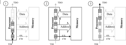
As a preface to discussing the forensic application of test circuits, the process of interacting with an embedded system memory via this interface is described here in general terms. The first test vector contains an address of a memory location and control signals (ce, r/w) with a read command. This test vector is clocked into the boundary-scan register using TDI (step 1 in Figure 8.6). After the test vector is shifted into the boundary-scan register it is activated with TMS, activating the address and command bus (step 2 in Figure 8.6). In response, the requested data from memory is placed on the data bus. In order to extract the requested data it is first necessary to execute a capture command with TMS to obtain a second test vector, containing the data from the data bus. This test vector with memory data is shifted out of the boundary-scan register and can be read from TDO (step 3 in Figure 8.6). Repeating this process with all possible memory addresses results in a complete memory image.
If an onboard processor supports JTAG to execute debug commands, it can also be used for data acquisition. Normally the execution of embedded software has to be stopped before debug commands can be executed. Examples of debug enabled chips are chips with an ARM7 or ARM9 core. These cores have some special registers to control the debug mode of the core. One register is used to put machine instructions in an instruction pipeline. For example, a value of a memory location can be read by placing an instruction to “store memory location to register R14” (for example, STR R[index], [R14]) in the pipeline and read the value of register R14 afterward. Because the core is still active in debug mode, memory locations might be based on virtual addresses because of an active memory manager.
Boundary-scan techniques can also be used to acquire data from RAM memory but precautions are needed to assure that the memories are regularly refreshed to keep the data valid.
Physical Connectivity
The most generic way to acquire data from physical memory of an embedded system is to connect the acquisition device directly to the chip containing the target data. In this way the low-level access protocol as described by the chip's data sheet can be used to address each individual memory location. The most practical way for physical connectivity is to remove the chips from the printed circuit board and read the data with an external reader like a commercial device programmer. Because RAM memories will lose data without proper power and control signals, direct access needs to be done in circuit with special test clips applied over the existing chip pins. Special precautions are needed to avoid conflicts between the acquisition device and other components on the printed circuit board.
On 9 May 2006 a 51-meter-long inland vessel loaded with 575 tons of copper sank after it was hit by an almost 200-meter-long tugboat. The 60-year-old boatman of the inland vessel was missing and found dead several days later. The GPS navigation device of the tugboat was known to store track-log coordinates in SRAM memory. A method was developed on a similar reference device to physically connect to the SRAM chips and acquire the data while the memory was still powered. From the acquired data all track-log points were recovered and plotted on a map. The boatman of the tugboat was found guilty of not changing his course on time while he could foresee a hit with his current course.
Desoldering
For nonvolatile memory chips, physical removal is the most generic acquisition method. It can even be used if the system as a whole is not functioning anymore, after being burned, exposed to fluids, or deliberately damaged. Most nonvolatile memory chips nowadays are packed in a Thin Small-Outline Package (TSOP) or micro Ball Grid Array (BGA) casing. Dedicated desoldering equipment is preferred to prevent damaging the chips and thereby causing data loss. Figure 8.7 shows the preferred way to desolder TSOP chips. Hot air is blown on the edges of a TSOP chip. Therefore the temperature of the chip itself stays lower than the temperature of the solder connections. When the solder is melted a vacuum air gripper pulls the chip off.

Micro BGA chips don't have pins but instead use small balls on the bottom of the package for connecting the chip to the printed circuit board (Figure 8.8).
Micro BGA chips can be removed with hot air using a rework station. A rework station uses a temperature profile to heat up the printed circuit board and target chip in a controlled way, preventing chip damage and data loss caused by sudden temperature changes. The temperature profile is different for each chip and printed circuit board because the convection of heat is subject to many parameters like the thickness of the printed circuit board, the number of layers, the size of the nozzle and the chip size. Always practice on a reference model before removing a chip from an exhibit and use a temperature sensor mounted at the side of the memory chip for temperature logging.
Preparation
Pins of a TSOP chip can be cleaned with solder wick and flux remover. If a micro BGA chip is removed from a printed circuit board the balls on the chip are damaged. Some solder is left behind on the chip and the rest is left behind on the printed circuit board, resulting in balls of different sizes. Since reading sockets are designed for virgin chips with balls of equal size, the differences in ball size on an unprepared, desoldered micro BGA chip result in bad connections. One solution to this problem is to repair the balls of the chip, a process called reballing. Although other methods are available the best method is to use a reballing machine (Retronix Ltd., 2008). This machine puts little balls of solder on the connection and locally melts it with a laser beam, but this machine is very expensive. An alternative solution to reballing is described in the next section.
Connecting
After cleaning, the flash memory chip can be read with a commercial device programmer. These device programmers usually have several types of Zero Insertion Force (ZIF) sockets for connecting the chip to the programmer. Flash chips in TSOP casing usually use a package with 48 pins. Therefore most TSOP chips can be read with only one type of socket. Micro BGA chips, however, are found in many different sizes and differ greatly in number of balls and spacing between the balls (pitch). Usually these chips have casings between 40 and 167 balls, and will probably have even more in the future. Obtaining the correct socket to read a particular chip can be difficult because of the large number (over 40 and growing), high cost, and long delivery time. A solution for this problem is to use a socket that can be adapted for many types of chip casings; see Figure 8.9 (Logic Technology, 2008).


These sockets use spring contacts called pogo pins positioned into a matrix with one specific pitch. The chip is pressed onto the springs and the springs correct the difference in height of the balls. The memory chip is held into position by a locator. This locator is specific for each type of casing and can be made relatively easily with a milling machine.
Reading
Memory chips can be read with commercially available device programmers (BPM Microsystems, 2008). A disadvantage is that a driver is needed for each type of memory chip. If a driver for a certain type of chip is not available, the manufacturer of the device programmer has to make this driver. This can take some time and is not always possible when a datasheet or reference chip is not available for evaluation and testing. An alternative approach is to use a custom-made universal memory chip reader. With such a reader, parameters like address bus size and data bus size are fully customizable. With NOR flash memory, a data structure can be read from the memory containing all necessary parameters for data extraction. This structure is part of the common flash interface standard (Jedec Solid State Technology Association, 2003). For NAND flash chips a limited number of different protocols exist. These protocols can be enumerated with software until the correct one is found. Due to the automatic configuration properties of a custom made universal flash chip reader, it is sometimes possible to read flash chips even without having a datasheet.
Not all flash can be addressed directly, especially NAND flash arrays that are part of multichip modules that are addressed via RAM buffers with configurable sizes. If different tools use different configurations or storage policies for the order of sector data and spare data, acquisition results will be ambiguous and hard to share between different information recovery tools. These problems can be avoided with the following conventions:
1. For direct addressable flash memory (possibly part of a multichip module): Store data exactly in the linear order, starting from address zero, as if the address bus of the memory array is directly controlled.
2. For flash memory that is not directly addressable, like NAND flash arrays (possibly part of a multichip module):
Store data in page order, starting from address zero, using the internal memory map of the flash memory. For small page (e.g., 528 bytes) NAND flash this results in: <512 bytes main><16 bytes spare>…<512 bytes main><16 bytes spare>. For larger page NAND flash (e.g., 2112 bytes) this results in: <2048 bytes main><64 bytes spare>…<2048 bytes main><64 bytes spare>.
3. Store additional metadata describing the acquired chips and acquisition policies. For example:
▪ MemoryIdentifier: Unique string to identify different memories within one system;
▪ MemorySize: Size of the memory in bytes;
▪ MemoryEndians (only for word addressable chips): “Big” if the leftmost byte of a word is written to file first, “Little” otherwise.
When a modern NAND flash chip is acquired repeatedly and the acquisition results are compared, some bits might not be stable between different acquisitions. These erroneous bits are normally corrected by a connected controller that uses the error-correcting codes stored in the spare area of the flash and an error-correcting algorithm. The error-correcting algorithm needs to be known in order to perform the error correction without the controller after acquisition. Uncorrectable errors are most likely originating from blocks that are marked bad with some flag in the spare area or in another area reserved for metadata.
Information Recovery
When all data have been acquired from a target device, recovery operations are needed to transform the low-level device data into human readable information. Information can originate from active data or deleted data. 11 Active data is guaranteed to be complete because it is used by the system in its current state. 12 Deleted data originates from past states of the system and is not necessarily complete. Information can be classified further into user-related information and system-related information. The term recovery is used for actions on both active and deleted data. Recovery techniques depend on the complexity of the embedded systems. Some systems don't have an operating system or file system, which sometimes results in data structures that are inspired more by the system programmers and not on standardized storage principles.
11Both active and deleted data can be essential or nonessential (Carrier, 2005). Take a timestamp from a call entry found in the memory copy of a mobile phone as an example. This timestamp is nonessential because it is related to the internal clock of the mobile phone. It can originate from active data or from data deleted by a user or a system process.
12In real-life systems even active data can be corrupt, caused by unhandled exceptions or implementation errors (e.g., a multimedia card from a photo camera that has been put in a card reader without write blocker on Windows XP).
Record Recovery
Data records are often used for information encoding in embedded system memories. The most basic variant just uses hard-coded memory locations and fixed data sizes possibly grouped into tables. More advanced variants use tag length value (TLV) encoding sometimes combined with relative pointers for linked list constructions. The generic method to reconstruct the information is reverse engineering of the firmware but mostly it is faster to use a reference device of the same brand and type and use trial-and-error methods with known data.
In 2004 a patient's death was probably caused by an overdose of medicine injected with an infusion pump. The cause of the overdose was unknown and the infusion pump was examined by a forensic laboratory. A primary goal of the forensic examination was to retrieve the last configured medicine dose. A reference device was obtained from the manufacturer and disassembled. The device contains an EEPROM memory for storage of nonvolatile data. The I/O lines of this EEPROM were analyzed during experiments with different medicine dose settings. The configured dose appeared to be written to a static EEPROM address when the device was switched off. With this knowledge the EEPROM of the questioned infuse pump was desoldered and read. The extracted dose value could not have caused an overdose but was also not consistent with the expected dose. During further technical analysis of the infusion pump no technical defects were found except for one user interface inconvenience that could lead to erroneous dose entries. Sometimes when a numerical key was pressed, a visual feedback signal was given but the key entry was not registered. Although this could be seen on the display it was reported as a probable cause for wrong dose entries.
The following software tools might be helpful in the process of record recovery.
Hex Editors
Hex editors are the primary tool for analyzing unknown data from embedded system memories (BreakPoint Software, 2008 and Casey, 2004). Besides common hex editor functionality like visual formatting, navigating, searching, and decoding of simple data types, the following features are very useful for record recovery:
▪ Color mapping applies a specific color to all bytes with a user-specified pattern. This is useful to recognize repeating patterns or to deemphasize uninteresting data.
▪ Bookmarks are useful to interactively find out how data are structured and to describe the individual fields of each record type. These bookmarks are linked to file addresses and can be saved and reloaded separate from the file containing the memory data. Figure 8.10 shows an example of WinHex bookmark functionality to dissect a deleted missed call record of a partial NOR flash copy from a Nokia 1600 phone.

▪ Structure definitions can be used to render binary data into structured data. Both WinHex and Hex Workshop support text files with application-specific syntax to specify different data structures. These data structures can be mapped to file addresses causing a more structured view of the data. This can be useful, for example, to find out how instances of a specific record type are grouped. Unfortunately these mappings cannot be saved for later reuse, only some basic decoding of built-in data types is supported, and there is no method for exporting the structured and partially decoded data.
IDA Pro Disassembler and Debugger
IDA Pro is a software tool built for disassembling and decompiling machine code (Eagle, 2008). This tool could be used to load data from embedded system memory that contains data encoding functions and to reverse engineer them to reconstruct relevant system and user information. Although possible, this would be very complex and time consuming. A more practical approach is to (ab)use IDA as an advanced hex editor with additional functionality for repeated decoding of memory data. This approach has two phases: A development phase that is performed once for each specific storage format, and a production phase where information from known storage formats can be extracted with a few mouse clicks. Figure 8.11 shows a screenshot of IDA during the development phase.

The development phase consists of the following steps:
1. The memory file is loaded into IDA as a binary file with the default metapc processor option and with all analysis options disabled because processor features are not needed. Different views, such as hexadecimal format or examining all strings that satisfy specific configurable criteria, can be useful for interpreting data structures. Similarly, reverse engineering functions, like applying different number and character formats and adding comments to different data parts, support the interactive process of finding out how data are structured. The goal of this step is to define structures for all record types of interest. Each structure may be specified up to the individual field details but this is not really necessary. For structure creation the IDA structure window can be used. Structure definitions can also be imported and exported in the format of the IDA built-in scripting language called IDC. This enables the use of external editing tools and structure reuse. The final result of this step is an IDC StructureDefinition.idc script with all relevant structure definitions for a specific storage format.
2. After defining the structures, all addresses need to be found where these structures are used. In the early development phase this is done manually from the IDA view and with the Struct var… dialog. As soon as more knowledge is collected, IDC scripting can be used to automate this process. All identifiable structures are saved by IDA into cross-reference lists for later use. The ultimate goal of this step is to develop an IDC StructureSearch.idc script that finds all memory locations for each structure type.
3. The next step is to decode data from recovered structures into human readable information. This can be done interactively with IDA's commenting functionality. Decoded data are added as posterior comments to recovered data structures. A suitable markup language for this is XML. Again this process can be started manually, and as soon as specific encoding formats are understood well enough, the IDC scripting language can be used. This step results in a StructureDecode.idc script that decodes all data referenced by the structure cross-reference lists.
4. The last trivial step is an InformationExtract.idc script that exports all posterior comments to one XML file that can be viewed directly with a web browser or with additional formatting using a style sheet.
Scripts developed for a specific storage format can be used on data acquisition files originating from similar devices. The memory file just needs to be loaded into IDA and the four IDC scripts need to be loaded and executed one after each other.
File System Recovery
File system recovery uses the acquired low-level data to rebuild the high level hierarchy of directories, subdirectories, and files. For data originating from flash file systems (as explained earlier in this chapter) this means finding out how the flash translation layer maps physical data to logical data and how the difference between active and delete data can be determined. 13 The result of this “flash translation layer analysis” is a method that splits the physical data into two parts: a part with all logical sectors in the right order belonging to the actual file system and another part with all other data not belonging to the (current) file system. The first part can be further analyzed by existing forensic tools for file system recovery (Carrier, 2005). Analysis of the second part is more complex and depends a lot on the setup and user behavior of the originating system.
Data Carving
As discussed in Chapter 2, “Forensic Analysis,” data carving is a technique that searches through acquired data for information that cannot be recovered via the original file system structures. Using common data carving tools directly on acquired data from flash memories might not give many useful results because the arrangement of blocks in flash can be very different from the way blocks are arranged on magnetic storage media. This difference is due to the behavior of the flash translation layer that is designed to maximize the life span of individual flash memory cells. Therefore, if generic data carving tools are used on data acquired from flash memories, it is preferred to preprocess the acquired data in such a way that the resulting sector order resembles the sector order commonly found on magnetic storage media.
Popular data carving targets for mobile phone examinations are photos and videos made with built-in cameras and deleted by users. Photos are mostly stored in JPEG format and videos in 3GP format with MPEG-4 or H.263 video streams and AAC or AMR for audio. After flash translation layer specific reordering of sector data, JPEG fragments can be carved with existing carving tools (Garfinkel, 2007). 3GP carving results are much better if carving is targeted toward individual video frames and when the carving tool also uses the metadata stored in 3GP formatted files (Luck & Stokes, 2008). After automatic carving tools are used, improved results can often be achieved with tool assisted manual examination. Most of the existing forensic tools are not publicly available (Bijhold et al., 2007). For 3GP analysis, defraser can be useful. Defraser is a forensic analysis application that can be used to detect full and partial multimedia files in datastreams (Netherlands Forensic Institute, 2007).
Forensic Tools for Information Recovery
There are an increasing number of forensic tools especially designed to recover information from mobile phones, PDAs and navigation systems (Siedsma, 2008). These tools are useful for getting quick results but have major limitations from a forensic perspective. To a great extent these limitations are caused by small differences in firmware versions potentially causing big differences in resulting output. Current good practice is to use different tools, compare the differences, and additionally use hex editors and scripting tools for verification and additional searching.
Micro Systemation uses a promising approach to bridge the gap between physical and logical data acquisition with their XACT and .XRY products (Micro Systemation AB, 2008). XACT uses flash loader technology as one of the techniques for physical data acquisition. Data acquired from mobile phones and other sources can be added to an XACT project file and examined using the built-in hex editor. Reconstructed information can be added to nodes of different types. This can be done automatically with delivered data decoders or manually from within the XACT user interface. When a saved XACT project file is loaded into the .XRY reader, node data originating from so-called Catalog nodes are presented in a similar way to data originating from the .XRY logical acquisition tool. Node data can also be exported to files. Unfortunately the current version has no scripting functionality, which makes user-initiated decoding very impractical. Figure 8.12 shows data from a mobile phone, acquired and decoded with XACT and loaded into .XRY for further analysis and presentation. The header string ftyp3gp4 in Figure 8.12 is known to belong to video files.

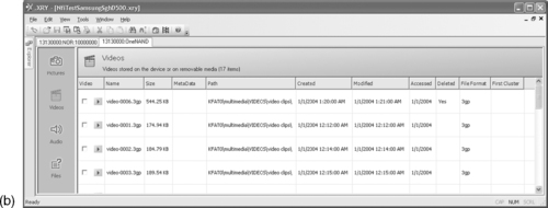
Information Recovery from a Samsung SGH-D500 Phone
A Samsung SGH-D500 phone contains a multichip package with RAM, NOR flash, and NAND flash. Physical data acquisition from the NOR and NAND flash memory results in two files: 32MB for the NOR flash and 132MB for the NAND flash. The NOR flash contains system data and user data stored in custom record formats. The NAND flash contains a FAT16 file system. Figure 8.13 depicts the NAND array structure as described in the datasheet (Samsung Electronics, 2004).
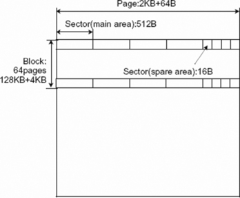
After a fire, a man's burned body was discovered. The man turned out to be dead before the fire started. During the police investigation, the boyfriend of the victim's daughter was marked as suspect. A low quality picture and video file of the fire were found on his computer but not in the .XRY examination results of his mobile phone. JTAG was used to acquire the full NAND flash memory and Python scripts were used to reconstruct the logical sector order and FAT file system. No fragments of the questioned picture and video files were found in the reconstructed file system data. The remaining acquired data allocated to the active FAT file system was reordered with a heuristic ordering method. In the ordered blocks 73% of data from the video file was found in consecutive logical blocks. The defraser tool (Netherlands Forensic Institute, 2007) was used to reconstruct the video content of this fragment and it turned out to contain similar content of a fire as visible in the video found on the suspect's PC. Five months after the fire, the daughter of the victim confessed to murdering her father with the assistance of her boyfriend.
Four 512-byte data sectors are grouped into one page together with four 16-byte parts of spare area data. The data sheet explains the assignment of the spare area bytes suggesting that logical sector numbers (LSN) should be stored in bytes 3 to 6 of each 16-byte spare area part (Figure 8.14).

Flash Translation Layer
Experiments with known data revealed that the LSN is stored in bytes 3 to 5 with the least significant byte first as demonstrated:
FFFF 5C35 00FE 00FF 0C03 CCFF
FFFF FFFF
LogicalSectorNumber = 0x00355C =
13660
FFFF 5D35 00FE 00FF F0FF 3CAA
FEFF FFFF
LogicalSectorNumber = 0x00355D =
13661
An acquired flash memory file gives different physical sectors with the same logical sector number. The first sector of each 128 Kbyte + 4 Kbyte block contains a four-byte block number starting on the twenty-first byte, and a four-byte block version starting on the seventeenth byte, as demonstrated:
5853 5231 6400 0000 0F00 0000 0100 0000 XSR1d.
0701 0000 0100 0000 FC00 0000 0000 0000.
BlockNumber = 00000001h = 1d
BlockVersion = 00000107h = 263d
For physical sectors with identical logical sector numbers the physical sector with the highest physical address must be used within the block with the highest block version number. With this knowledge a sector list can be built containing items for each encountered logical sector number. Each list item is also a list containing all physical addresses of sectors with a specific logical sector number, sorted on block version and physical address within a block. An example fragment of such a list is shown here:
SectorList[23] = {0x01264f20, 0x01f77180}
SectorList[24] = {0x01265550, 0x01265340, 0x01265130, 0x01f77390}
SectorList[25] = {0x01265760, 0x01f775a0}
Recovering the Actual File System
After building the sector list the actual file system can be recovered by appending 512 bytes (one data sector) from the flash memory, for each sector list item, starting from the first physical address in the sector list item (the addresses marked light gray above) to a file storing the complete file system. If a logical sector number is not present in the sector list, 512 dummy bytes are written to the output file. The resulting file can be further processed with file system forensic tools as described in Chapter 2, “Forensic Analysis.”
Recovering Other High Level File System Data
Not all acquired data from the flash memory data has been used to reconstruct the actual file system. The remaining data can contain remnants of older instances of the file system, such as when logical sectors belonging to a file that has been deleted and which logical sector numbers have been reused by the high level file system. This especially applies to small data objects with a high refresh frequency (e.g. FAT), so many remnants of older versions might exist in the flash memory file. In addition, portions of acquired memory can contain old file system information because those areas of memory were used by the embedded system's firmware for other purposes, such as workspace for the flash file system during flash memory clean-up operations.
The sector list introduced before contains information that can be used to reconstruct prior file system remnants. Assuming the first address of each sector list relates to the current file system, the subsequent addresses (marked dark gray earlier) can be used to generate an older instance of the file system. However, the older reconstructed file system will most likely not be complete or fully consistent since sectors that are not part of the current high level file system can be overwritten by the flash file system at any time.
For data carving purposes it is preferred to put all remaining data sectors in an order that maximizes the carving results. For this particular phone the following strategy proved to be useful:
1. For each item in the sector list, remove the first address because this address has already been used to generate the actual high level file system.
2. For each remaining item in the sector list with less address items than a certain threshold:
(a) Initialize the current address item to the first address of the first sector list item.
(b) Export this current address item and remove it from the sector list. Then look at all address items of the next sector list item and try to find the best match. The following heuristic is used for the matching:
i. Is next sector: Because contiguous information is most likely put in adjacent physical sectors, if the absolute difference between the value of the current address item and the value of the next address item is equal to the sector size, this address is selected and no other addresses are matched.
ii. Is next block: When a physical block is full, additional information is most likely saved at the start of a new allocated block. Therefore, if the value of the current address item is the last data sector of a block and the value of the next address item is the first data sector of a block, this address is selected and no further matching is done.
iii. No match: Do not pick an address but repeat step (a), with the first address of the first item in the sector list in the hope that other physical sectors might exist that provide a better match.
(c) If a match is found, go to (b) with the matched address as current item's address of the current sector list item.
3. Repeat step 2 until no sector list items exist with fewer address items than the threshold value.
4. All remaining items from the sector list are selected and their related data sectors are exported.
Analysis and Interpretation of Results
When all relevant low-level device data are converted into human readable information, the forensic value needs to be determined. The way to do this depends heavily on the modus operandi and the characteristics of the exhibits. In this section some aspects are covered that are specific for analysis and interpretation of evidence originating from embedded systems.
Timestamps
Time aspects are important in most forensic investigations (Willassen, 2008). A timestamp is a recorded representation of a specific moment in time. Timestamps found in embedded systems originate from local clock chips or are derived from external systems with timestamp information like GPS, NTP, RDS, or SMS. Origin, transport, and storage format can cause different timestamps for the same time event. As a general rule, when acquiring data containing timestamp information, it is important to record an accurate time reference as close as possible to the moment when the timestamp is acquired. The time reference can be a radio controlled clock, a computer clock synchronized via the NTP protocol or any other accurate reference with known UTC offset.
On 27 October 2005 a big fire in a prison complex at Amsterdam's Schiphol Airport killed 11 people and injured 15 others. During the forensic investigation a lot of digital traces were collected originating from SCADA14 systems like surveillance, fire control, and personnel communication. Some of these systems were severely damaged by the fire. During data acquisition radio controlled clocks and NTP synchronized examination computers were used to annotate the differences between UTC time and the local time values on the different exhibits. The detected time differences varied between two minutes and 12 hours. From the recovered information a database with more then 500,000 time-synchronized events was reconstructed. From this database 14 events originating from three different sources were the most important for fact finding.
Timestamps are relative to the state of some local clock at a particular moment in time. Mobile phone timestamps, for example, can be relative to the built-in clock, the clock of the connected network or another external time reference. Some phones reset their clock value to a type-specific value after removal of the battery. Others phones have a backup energy source so depending on the capacity the clock keeps ticking. Still other phones store their clock value in nonvolatile memory just before powering down and continue from this value after being switched on. Accuracy of built-in embedded system time references is not only depending on the clock chip but also on environmental conditions like temperature and the way a system uses the clock chip.
A wide variety of storage formats are used for storing timestamp data in embedded system memories. To illustrate, the timestamp “30 April 2008 14:30:59 UTC” is encoded as follows in some formats found in different mobile phone memories:
▪ 0x80400341039500 (ETSI SMS)
▪ 0xB19E0CA3 (Nokia)
▪ 0x07D8041E0E1E3B (Nokia)
▪ 0x26041E0E1E3B (Motorola)
▪ 0x00E129CB0E8B2EC0 (Symbian)
▪ 0x481882A3 (POSIX)
The evidentiary value of timestamps can be further analyzed by comparing timestamps originating from one event and generated by different systems. Most connection events for mobile phones, for example, generate local timestamps in the mobile phone memory but also in the call detail records of the service provider. SMS messages transmitted via a service provider toward a mobile phone, and stored in the phone memory with the original transmission format, have timestamps originating from the time reference of the service provider's message center. Timestamps from the service provider are in general more reliable than the local timestamps of the mobile phone.
A novel method for identifying the time when specific audio or video files are created uses the 50/60Hz electrical network frequency (Grigoras, 2007). When digital equipment is used to record a conversation or event, it captures not only the intended speech but also the 50/60Hz electrical network frequency (ENF). This might even occur if the recording device is battery-powered and in proximity to other mains-powered equipment or transmission cables. In a real electrical network the ENF is not fixed at precisely 50/60Hz. Over time, frequency variations inevitably occur, principally because of differences between produced and consumed power. These variations can be used for forensic analysis using a reference frequency database recorded in a laboratory or obtained from the electrical network company. Forensic applications of ENF can not only be used to determine or verify when an audio or video file was recorded, but also to indicate the geographical area and to check the integrity of an embedded recording.
Classification, Comparison, and Individualization
Classification, comparison, and individualization of mobile phones and associated data are illustrated next, with some examples.
GSM and UMTS Phones
GSM or UMTS phones can be classified to a brand and type with their IMEI. IMEI is the abbreviation for International Mobile Equipment Identity, the unique number that each mobile phone (or other mobile device within GSM or UMTS) is obliged to have. The IMEI was introduced to uniquely identify all the mobile equipment present, independent of the subscribers who use this equipment. The IMEI of a device consists of 14 decimals supplemented with a check decimal, and can usually be found on a sticker under the battery and electronically in the nonvolatile memory. On most phones the IMEI can be extracted manually with the key combination *#06# and logically with the AT+CGSN AT-command. IMEIs ranges are registered by approved organizations and can often be queried to determine the brand and type from the IMEI number (International Numbering Plans, 2008). CDMA mobile phones have a similar identifier called the Mobile Equipment Identifier (MEID).
A phone can be used in the mobile network only with a valid IMSI (International Mobile Subscriber Identity). The IMSI is stored in the (U)SIM and is intended primarily for identifying the subscriber. IMSIs are structured with country and provider codes and administrated by the service providers and network providers.
On 3 December 2002 IKEA received a blackmail letter stating that two explosive devices had been placed in IKEA shops in the Netherlands and a third device would be used unless a ransom was paid. The next day improvised explosive devices (IEDs) were found in two IKEA shops and were disarmed by a bomb squad. The IEDs consisted of an explosive charge, a detonator, and a mobile phone used as a remote controlled activator. The GSM phones had no SIM card but the detonators could still be activated with the built-in alarm clock or by pressing a keyboard button. A forensic examination of the nonvolatile memories of the phones revealed several IMSIs belonging to SIM cards that had been used in the phones before. These IMSIs were an important clue that led to several suspects, and after reading their phones and SIM cards, many cross links could be found (Figure 8.15). This information was accepted in court as important evidence to prove the link between the suspects and the IEDs.


Multimedia Data from a Specific Mobile Phone
After recovering (deleted) multimedia information like pictures, movies, or sounds, a legitimate forensic question is whether a specific item was made with the target phone. For this classification and individualization the following artifacts might be helpful in testing different hypotheses:
▪ File system information like file-naming schemes, file locations, and file timestamp information.
▪ Metadata from the multimedia formats like video codec, audio codec, audio bit rate, and timestamps. Table 8.2 shows some differences in file system information and metadata between different phone types.
▪ Photo Response Non-Uniformity (PRNU). PRNU is a relatively weak pattern of pixel-to-pixel sensitivity differences in digital image sensors. PRNU is primarily caused by varying sensitivity of individual pixels to light due to inhomogeneity and impurities in silicon wafers and imperfections introduced by the sensor manufacturing process. PRNU is believed to cause unique fingerprints of imaging sensors (Alles et al., 2008 and Chen et al., 2007). Besides the questioned image material, PRNU for forensic identification also needs the camera in question for generation of reference data or existing reference data originating from that camera.
(Past) Existence of Specific Files
Existing forensic tools for file system analysis try to recover data belonging to deleted information. These tools are not fully aware of the physical media from which the acquired data originates. This knowledge of the physical properties might improve the recovery process. Flash file systems, for example, often contain different versions of the same data objects because flash memory cannot be erased in small quantities. Especially for small objects (much smaller than the erase block size) with a high update frequency, a lot of old versions might exist outside of the normal high level file system. Data acquired from flash memories might contain additional data, belonging to past states of the file system, not accessible at the file system level.
File allocation tables and directory entries are an example of such artifacts. These items are updated frequently, and are relatively small compared to the erase block size of flash memory. This may result in a lot of physical instances of the same logical sector. To give an idea of the amount of different versions: in a case with a Samsung SGH-D500 mobile phone the acquired flash memory file contained 83 versions of some part of the FAT and 1464 versions of the directorymultimediaVIDEOSvideo clips where all user recorded video movies are stored by default. A common forensic tool will show the last version of the directory, possibly with some files marked as deleted but from the other versions of the directory data a significant amount of user behavior can be reconstructed. The same holds for other data objects although larger objects (like movie files) are likely to be (partly) overwritten earlier after deletion because they occupy complete flash blocks, which can be reused immediately after deletion.
Determine Functionality
Another legitimate forensic question is to determine the functionality of a specific system. Some examples are fraud cases, where a specific electronic system is believed to copy magstripe data from financial cards and record entered PIN codes, or terrorist threat cases, where improvised explosive devices with remote-control electronics are used to trigger explosives. After acquisition and recovery of stored data the following techniques proved to be useful for determining functionality and behavior of embedded systems.
Reconstruction of Electrical Diagrams From Electronic Equipment
The electrical diagram of basic printed circuit boards can be retrieved manually with a multimeter and established with the aid of CAD/CAM tools. For more complex systems additional inspection and analysis tools are needed. It might also be necessary to disassemble the equipment.
Reconstruction of (Embedded) Software
Disassemblers and debuggers are the primary tools for determining the functionality of embedded software as discussed in the section on the IDA Pro Disassembler and Debugger earlier in this chapter. It is not always possible to extract embedded software from microcontroller memories, for example, because they are read-protected. Reverse engineering the microcontroller in order to bypass the protection mechanism is an expensive and time intensive solution. If source code is available from other sources (for example, from a seized computer), the following method can be used to find out whether the code in the program memory is based on the (source) code that has been discovered:
▪ The discovered source code is translated into machine code with the same development tools as found on the seized system.
▪ A microcontroller of the same type is programmed with this machine code.
▪ Two measurements are then made on the system under investigation. During the measurements all relevant input and output pins of the microcontroller are recorded, first with the target chip and then with the programmed reference chip.
▪ The measurement data consist of lists containing all points in time where pin data changed. Statements on the functionality of the target chip are depending on the similarity of both measurements.
This method can be used more generically to compare an evidentiary item with reference chips that have known functionality.
The Future
Forensic investigation of embedded systems has grown out of its infancy and can now be classified as leading edge. Dedicated forensic tools are emerging, papers are being published, and an increasing number of people are getting involved in this area. There is still much work to be done. Low-level acquisition of embedded system memories can be performed by only a few highly specialized forensic laboratories, with the exception of a very limited set of devices that are currently supported by user-friendly tools. There are no standard procedures or test methods for low-level memory acquisition. The few tools for data analysis that currently exist are not good enough to rely on without case-by-case testing on reference devices. Most data analysis needs to be done with ad-hoc methods without much structural basis.
There is a high demand for cooperation with the industry because a lot of time is spent building knowledge about the working and behavior of systems that are designed and built by people who already have most of that knowledge but are not allowed to share it. Fast technological innovations and an increasing demand for more security to protect personal data stored in digital devices require an increase in the amount of resources for investigating these fascinating devices. Although research can improve forensic techniques for analyzing genetic materials like DNA, it is still possible to use existing methods on future traces because the fundamental makeup of the human race is not changing rapidly. Conversely, all current embedded systems will be replaced by different technology within a decade, and ongoing research is necessary to support forensic examination of current and future embedded systems.
Abbreviations
| AAC | Advanced Audio Coding |
| AMR | Adaptive Multi-Rate |
| API | Application Programming Interface |
| ARM | Acorn RISC Machine |
| AT | Attention |
| BGA | Ball Grid Array |
| BIOS | Basic Input/Output System |
| CAD | Computer Aided Design |
| CAM | Computer Aided Manufacturing |
| CCTV | Closed Circuit Television |
| CDMA | Code Division Multiple Access |
| CPU | Central Processing Unit |
| DIP | Dual In-line Package |
| DNA | Deoxyribonucleic acid |
| DRAM | Dynamic Random Access Memory |
| DTC | Diagnostic Trouble Code |
| DUT | Device Under Test |
| ECC | Error-Correcting Code |
| ECU | Electronic Control Unit |
| (E)EPROM | (Electrically) Erasable PROM |
| ENF | Electrical Network Frequency |
| ETSI | European Telecommunications Standards Institute |
| FAT | File Allocation Table |
| FeRAM | Ferroelectric RAM |
| FIFO | First In/First Out |
| FPGA | Field Programmable Gate Array |
| GPS | Global Positioning System |
| GSM | Global System for Mobile Communications |
| I/O | Input/Output |
| ICCID | Integrated Circuit Card ID |
| ICT | Information and Communication Technology |
| IED | Improvised Explosive Device |
| IMEI | International Mobile Station Equipment Identity |
| IMSI | International Mobile Subscriber Identity |
| JTAG | Joint Test Action Group |
| LGA | Land Grid Array |
| LSN | Logical Sector Number |
| MIPS | Microprocessor without Interlocked Pipeline Stages |
| MMU | Memory Management Unit |
| NMEA | National Marine Electronics Association |
| NTP | Network Time Protocol |
| OBEX | Object Exchange |
| OS | Operating System |
| PCB | Printed Circuit Board |
| PDA | Personal Digital Assistant |
| PGA | Pin Grid Array |
| PIN | Personal Identity Number |
| POS | Point of Sale |
| POSIX | Portable Operating System Interface |
| PRNU | Photo Response Non-Uniformity |
| PROM | Programmable ROM |
| PUK | PIN Unblocking Key |
| RAM | Random Access Memory |
| RDS | Radio Data System |
| RISC | Reduced Instruction Set Computer |
| ROM | Read Only Memory |
| SAM | Secure Application Module |
| SCADA | Supervisory Control And Data Acquisition |
| SCSI | Small Computer System Interface |
| SIM | Subscriber Identity Module |
| SIP | System In Package |
| SMS | Short Message Service |
| SMT | Surface-Mount Technology |
| SRAM | Static Random Access Memory |
| TAC | Type Approval Code |
| TAP | Test Access Port |
| TCK | Test Clock |
| TDI | Test Data Input |
| TDO | Test Data Output |
| TLV | Tag Length Value |
| TMS | Test Mode Select |
| TRST | Test Reset |
| TSOP | Thin Small-Outline Package |
| UMTS | Universal Mobile Telecommunications System |
| UPS | Uninterruptible Power Supply |
| USB | Universal Serial Bus |
| USIM | Universal Subscriber Identity Module |
| UTC | Coordinated Universal Time |
| UV | Ultraviolet |
| XML | Extensible Markup Language |
| ZIF | Zero Insertion Force |
References
Al-Zarouni, M., In: Introduction to mobile phone flasher devices and considerations for their use in mobile phone forensicsProceedings of 5th Australian Digital Forensics Conference. (2007).
Alles, E.J.; Geradts, Z.; Veenman, C., In: Source camera identification for low resolution heavily compressed imagesInternational Conference on Computational Sciences and Its Applications. (2008).
Ayers, R.; Jansen, W.; Delaitre, A.; Moenner, L., Cell phone forensic tools: An overview and analysis update, Available athttp://csrc.nist.gov/publications/nistir/nistir-7387.pdf (2007).
Bijhold, J.; Ruifrok, A.; Jessen, M.; Geradts, Z.; Ehrhardt, S.; Alberink, I., In: Forensic audio and visual evidence 2004–2007: A review15th INTERPOL Forensic Science Symposium. Lyon, France. (2007); Available atwww.forensic.to/webhome/enfsidiwg/Interpol-review-2007-audio-visual-evidence-paper.pdf.
BPM Microsystems, Device programmers. (2008) ; Available atwww.bpmmicro.com/.
BreakPoint Software, Hex workshop hex editor. (2008) ; Available atwww.hexworkshop.com/.
Breeuwsma, M., Forensic imaging of embedded systems using JTAG (boundary-scan), Digital Investigation 3 (2006) 32–42.
Breeuwsma, M.; de Jong, M.; Klaver, C.; van der Knijff, R.; Roeloffs, M., Forensic data recovery from flash memory, Small Scale Digital Device Forensic Journal 1 (2007).
Carrier, B., File system forensic analysis. (2005) Addison-Wesley Professional.
Casey, E., Tool review-WinHex, Digital Investigation 1 (2004) 114–128.
Chen, M.; Fridrich, J.; Goljan, M.; Lukáš, J., Source digital camcorder identification using sensor photo response non-uniformity, Proc. of SPIE Electronic Imaging (2007).
Ching-Yao, C., Fundamentals of crash sensing in automotive air bag systems. (2000) Society of Automotive Engineers, Inc, Warrendale, PA.
de Backer, C., Jaar-2000 checklist “Embedded systems”. Millennium Forum 2000. (1999) Compendium, Brussels.
DexMobile, RobLock. (2008) ; Available atwww.dexmobile.com/roblock_wm.aspx.
Eagle, C., The IDA PRO book. (2008) No Starch Press.
Feldman, A.J.; Halderman, J.A.; Clarkson, W.; Paul, W.; Calandrino, J.A.; Appelbaum, J.; et al., Lest we remember: Cold boot attacks on encryption keys. Proc. 2008 USENIX Security Symposium. (2008) ; Available athttp://citp.princeton.edu/memory/.
Fernico, ZRT. (2007) ; Available atwww.fernico.com/zrt.html.
Forensic Navigation, TomTology. (2008) ; Available atwww.forensicnavigation.com/.
FTS, Forensic Telecommunication Services Ltd. (2008) ; Available atwww.forensicts.co.uk/.
Garfinkel, S.L., Carving contiguous and fragmented files with fast object validation, Digital Investigation 4 (2007) 2–12.
GPS Utility Ltd, GPS Utility. (2008) ; Available atwww.gpsu.co.uk/.
Grigoras, C., Applications of ENF criterion in forensic audio, video, computer and telecommunication analysis, Forensic Science International 167 (2007) 136–145.
GSM-Forum, GSM-Forum. (2008) ; Available athttp://forum.gsmhosting.com/vbb/.
Guilfanov, I., IDA Pro disassembler and debugger. (2008) ; Available atwww.hex-rays.com/idapro/.
Harrill, D.C.; Mislan, R.P., A small scale digital device forensics ontology, Small Scale Digital Device Forensic Journal 1 (2007).
Hengeveld, W.J., Set of win32 tools to investigate wince devices. (2003) ; Available atwww.xs4all.nl/~itsme/projects/xda/tools.html.
Hoog, A.; Gaffaney, K., iPhone forensics—annual report on iphone forensic industry. (2009) ;http://chicago-ediscovery.com/wpinstall/wp-content/uploads/2009/03/iPhone-Forensics-2009.pdf; Available at.
IEEE Standards Association, IEEE Std 1149.1-2001 IEEE Standard Test Access Port and Boundary-Scan Architecture—Description. (2001) .
International Numbering Plans, International numbering plans. (2008) ; Available atwww.numberingplans.com.
Jedec Solid State Technology Association, Common Flash Interface (CFI). (2003) .
Jones, M.T., Anatomy of Linux flash file systems. (2008) ; Available atwww.ibm.com/developerworks/linux/library/l-flash-filesystems/.
Leyden, J., How to crash a phone by SMS, The Register (2001); Available atwww.theregister.co.uk/2001/11/28/how_to_crash_a_phone.
Logic Technology, Universal socket solution. (2008) ; Available atwww.logic.nl.
Luck, J.; Stokes, M., An integrated approach to recovering deleted files from NAND flash data, Small Scale Digital Device Forensic Journal 2 (2008).
LV Electronics, RF Shielded test enclosures. (2008) ; Available atwww.lvelectronics.be/RF%20enclosures.htm.
Mangard, S.; Oswald, E.; Popp, T., Power analysis attacks—revealing the secrets of smart cards. (2007) Springer Science+Business Media, LLC.
Me, G., In: Internal forensic acquisition for mobile equipmentsProceedings of the International Parallel and Distributed Processing Symposium (IPDPS). (2008).
Micro Systemation AB, SIM id-Cloner. (2006) ; Available atwww.msab.com/en/mobile-forensic-products/Sim-id-Cloner-mobile-forensic-tool/.
Micro Systemation AB, XACT. (2008) ; Available atwww.msab.com/en/mobile-forensic-products/XACT-mobile-forensic-application/.
Multi-com, gsm-technology.com. (2008) ; Available atwww.multi-com.eu/.
Netherlands Forensic Institute, TULP2G. (2006) ; Available attulp2g.sourceforge.net/.
Netherlands Forensic Institute, Defraser. (2007) ; Available atsourceforge.net/projects/defraser/.
Onderzoeksraad Voor Veiligheid, Draadaanvaring Apachehelikopter Bommelerwaard. (2009) ; 12 December 2007 (Dutch). Available atwww.onderzoeksraad.nl/docs/rapporten/Rapport_Apache_web.pdf.
Oxygen Software, Oxygen Forensic Suite. (2008) ; Available atwww.oxygen-forensic.com/.
Parker, S.P., McGraw-hill dictionary of scientific and technical terms. 5th ed. (1994) McGraw-Hill.
Planetbeing, Linux on the iPhone. (2008) ; Available athttp://linuxoniphone.blogspot.com/.
Project-a-Phone, Project-a-phone. (2007) ; Available atwww.projectaphone.com/.
Retronix Ltd, Retronix PCB Repair Services. (2008) ; Available atwww.retronix.com/.
Rosenbluth, W., Investigation and interpretation of black box data in automobiles—A guide to the concepts and formats of computer data in vehicle safety and control systems. (2001) ASTM.
Samsung Electronics, Datasheet of the multi-chip package MEMORY, 256Mbit (16M ×16) synchronous burst, multi bank NOR flash memory / 512Mbit(32M×16) oneNAND, flash*2 / 128Mbit(8M×16) synchronous burst uni-transistor random access memory. (2004) ; Available atwww.samsung.com.
Schatz, B., In: BodySnatcher: Towards reliable volatile memory acquisition by softwareDigital Forensics Research Conference 2007. (2007); Available atwww.dfrws.org/2007/proceedings/p126-schatz.pdf.
Siedsma, C., The electronic evidence information center—cellular/mobile phone forensics. (2008) ; Available atwww.e-evidence.info/cellarticles.html.
Signum Systems, JTAGjet. (2009) ; Available atwww.signum.com/Signum.htm?p=jtagjet.htm.
Wikipedia contributors, Embedded system. Wikipedia, The Free Encyclopedia. (2008) ; Available athttp://en.wikipedia.org/w/index.php?title=Embedded_system&oldid=270845478.
Willassen, S.Y., Methods for enhancement of timestamp evidence in digital investigations. (2008) Norwegian University of Science and Technology; Doctoral thesis. Available atwww.diva-portal.org/smash/record.jsf?searchid=1&pid=diva2:124235.
Zdziarski, J., iPhone forensics. (2008) O'Reilly.
Zdziarski, J., iPhone passcode easily defeated. (2008) ; Available atwww.zdziarski.com/.
..................Content has been hidden....................
You can't read the all page of ebook, please click here login for view all page.