
Chapter 4: Software architecture
Abstract
This chapter explains the software architecture of the Huawei Ascend AI processor. Firstly, the Ascend AI software stack is introduced, including the process orchestration (Matrix), the framework manager (Framework), the execution manager (Runtime), the Digital Vision Preprocessing (DVPP) module, the Tensor Boost Engine (TBE), and the Task Scheduler (TS). The neural network software flow is used to complete the generation, loading, and execution of the neural network model. Then, the development tool chain, Mind Studio, is introduced. It provides the auxiliary convenience for the realization process of the neural network.
Keywords
Software architecture; Process orchestration; Framework manager; Runtime; DVPP; Tensor boost engine; TBE; Task scheduler; Mind studio
The DaVinci architecture of the Ascend AI processor uses the customized computing resources in hardware design. The function execution is highly adapted to hardware which provides a powerful basis for improving the computing performance of the convolutional neural network. For a neural network algorithm, during the process from various open-source frameworks to the implementation of the model, and to the running on the actual processor, a multilayer software structure is required to manage the network model, computing flow, and data flow. The neural network software flow provides powerful support for the implementation of the neural network on the Ascend AI processor. In addition, the development tool chain is convenient for the application development of the neural network based on the Ascend AI processor. The software flow and development tool chain construct the foundation of the software stack of the Ascend AI processor, hence support from top to bottom of the execution process of the entire chipset.
4.1: Ascend AI software stack overview
To make the Ascend AI processor provide excellent performance, it is very important to design a complete software stack containing computing resources, a performance tuning framework, and various corresponding toolkits. The software stack of the Ascend AI processor can be divided into the neural network software flow, tool chain, and other software modules.
The neural network software flow mainly includes the process orchestration (Matrix), the framework manager (Framework), the execution manager (Runtime), the Digital Vision Pre-Processing (DVPP) module, the Tensor Boost Engine (TBE), and the Task Scheduler (TS). Neural network software flow is mainly used to complete the generation, loading, and execution of a neural network model. The tool chain mainly provides the auxiliary convenience for the realization process of the neural network.
As shown in Fig. 4.1, the functions of the main components in the software stack depend on each other to carry data flow, computing flows, and control flows. The software stack of the Ascend AI processor consists of four layers and an auxiliary tool chain. The four layers are the L3 application enabling layer, L2 execution framework layer, L1 processor enabling layer, and L0 computing resource layer. The tool chain provides auxiliary capabilities such as program development, compilation and commissioning, application process orchestration, log management, and performance analysis.
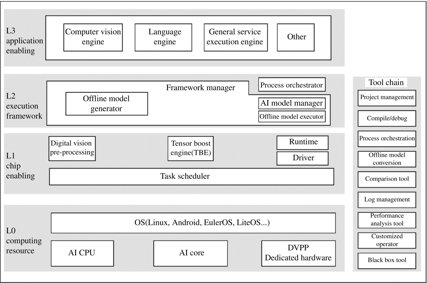
4.1.1: L3 application enabling layer
The L3 application enabling layer is application-level encapsulation. It provides different processing algorithms for specific domains, including the general service execution engine, computer vision engine, and language text engine. The general service execution engine provides a general neural network inference capability. The computer vision engine provides some algorithm encapsulation for video or image processing in the field of computer vision. In the speech and other fields, the language engine provides basic processing algorithms for data such as speech and text and provides language processing functions based on specific application scenarios.
In general service requirements, the corresponding computation process is defined based on the process orchestrator (Matrix), and then the general service execution engine implements specific functions. The L3 application enabling layer provides computing and processing capabilities for various domains, can directly use the framework scheduling capability provided by the next L2 execution framework layer and generates a corresponding neural network through a general framework to implement specific engine functions.
4.1.2: L2 execution framework layer
The L2 execution framework layer encapsulates the framework utilization capability and offline model generation capability. After developing and encapsulating the algorithm of a specific domain into an engine at the L3 application enabling layer, the L2 layer invokes the appropriate deep learning framework according to the characteristics of related algorithms. For example, it invokes the Caffe [1] or TensorFlow [2] framework to obtain the corresponding neural network and then generates an offline model through the framework manager. The L2 execution framework layer contains the framework manager and process orchestrator.
The online and offline framework is used in the L2 execution framework layer. The online framework uses mainstream deep learning open-source frameworks (such as Caffe and TensorFlow) to convert and load offline models so that they can perform acceleration operations on Ascend AI processors. For the network model, the online framework provides training and inference capabilities for network models and supports training and inference acceleration in different deployment scenarios, such as a single card, single machine, and multimachine. In addition to the common deep learning open-source framework, the L2 execution framework layer also provides the Huawei-developed MindSpore [3] deep learning framework, which functions similarly to TensorFlow. However, the neural network model generated by the MindSpore framework can directly run on the Ascend AI processor without hardware adaptation and conversion.
For the Ascend AI processor, the neural network supports online generation and execution. In addition, the offline framework provides the offline generation and execution capabilities of the neural network, that is, the Offline Model (OM) can have the same capability (mainly for the inference) under the deep learning framework. The framework manager includes the Offline Model Generator (OMG), Offline Model Executor (OME), and offline model inference interface. The framework manager supports model generation, loading, unloading, and inference calculation execution.
The Offline Model Generator converts the generated model and weight files in the Caffe or TensorFlow framework into offline model files and executes the files independently on the Ascend AI processor. The Offline Model Executor loads and unloads the offline model, converts the loaded model file into an instruction sequence that can be executed on the processor, and compiles the program before the execution. The load and execution of these offline models need to be coordinated by the process orchestrator (Matrix). It provides developers with a development platform for deep learning including computing resources, running frameworks, and related tools. In this way, developers can easily and efficiently compile AI applications running on specific hardware devices and schedule the generation, loading, and operation of the models. After transforming the original model of the neural network into an offline model that can be executed on the Ascend AI processor at the L2 layer, the Offline Model Executor transfers the offline model to the L1 processor enabling layer for task allocation.
4.1.3: L1 processor enabling layer
The L1 processor enabling layer is the bridge between the offline model and the Ascend AI processor. After receiving the offline model generated by the L2 execution framework layer, the L1 enabling layer provides the acceleration function for the offline model by using the acceleration library (Library) for different computing tasks. The L1 processor enabling layer is the layer closest to the underlying computing resources and is responsible for outputting the tasks of the operator level to the hardware. The L1 processor enabling layer mainly includes the DVPP module, TBE, Runtime, driver, and TS.
In the L1 processor enabling layer, the TBE is used as the core, and the acceleration calculation of the online and offline models is supported. The TBE contains the standard operator acceleration library. These operators have a good performance after being optimized. During the execution, the operator interacts with the Runtime at the upper layer of the operator acceleration library, and the Runtime communicates with the L2 execution framework layer to provide the standard operator acceleration library interface for the L2 to execute the framework layer. So a network model can find the optimized, executable, and accelerative operators to achieve the optimal implementation. If the standard operator acceleration library of the L1 processor does not contain the operators required by the L2 to execute the framework layer, you can use the TBE to write a new custom operator to support it, therefore, the TBE provides an operator with functional completeness for the L2 execution framework layer by providing both a standard operator library and a customized operator capability.
Under the TBE, the TS generates a specific computation kernel function according to the corresponding operator. The TS processes and distributes the corresponding computing kernel function to the AI CPU or AI Core according to the specific task type and activates the hardware using the driver. The TS itself runs on a dedicated CPU core.
The DVPP module is a multifunctional package oriented to the field of image and video processing. In a scenario where the common image or video preprocessing needs to be performed, the module provides various data preprocessing capabilities for the upper layer using dedicated hardware in the bottom layer.
4.1.4: L0 computing resource layer
The L0 computing resource layer is the hardware foundation of the Ascend AI processor. After the L1 enabling layer distributes the tasks corresponding to the operators, the execution of specific computing tasks starts from the L0 computing resource layer. It consists of the operating system, AI CPU, AI Core, and DVPP dedicated hardware modules.
AI Core is the computing core of the Ascend AI processor, which is for matrix computation of the neural network. And AI CPU completes the general computation of the control operator, scalar, and vector. If the input data needs to be preprocessed, the DVPP dedicated hardware module is activated and is used to preprocess image and video data. In specific scenarios, the AI Core provides the data format that meets the calculation requirements. The AI Core is responsible for computing intensive tasks. The AI CPU is responsible for complex computing and execution control functions. The DVPP hardware completes the data preprocessing function. The operating system is used to closely assist the three components to form a complete hardware system to provide execution assurance for the calculation on the Ascend AI processor.
4.1.5: Tool chain
The tool chain is a tool platform that supports Ascend AI processors and can be used for development by programmers. It provides support for customized operator development, debugging, network migration, optimization, and analysis. In addition, the programming interface provides a visual AI engine with a drag-and-drop programming interface, which greatly reduces the development effort of the applications related to the deep neural network.
The tool chain includes project management, compilation debugging, process orchestration, offline model conversion, comparison tool, log management, performance analysis tool, customized operator, and black box tool. Therefore, the tool chain provides multilevel and multifunction services convenient for application development and execution on this platform.
4.2: Neural network software flow
To implement and execute a neural network application, the Ascend AI software stack is a bridge between the deep learning framework and the processor. It is a software flow that supports the high-performance computing for the neural network. It provides a quick conversion shortcut for the neural network from the original model, to the IR graph, and then to the independent execution of the offline model. It focuses on the generation, loading, and execution of offline models and aggregates functional blocks such as process orchestrator, DVPP module, TBE, framework manager, Runtime, and the TS to form a complete functional cluster, as shown in Fig. 4.2.
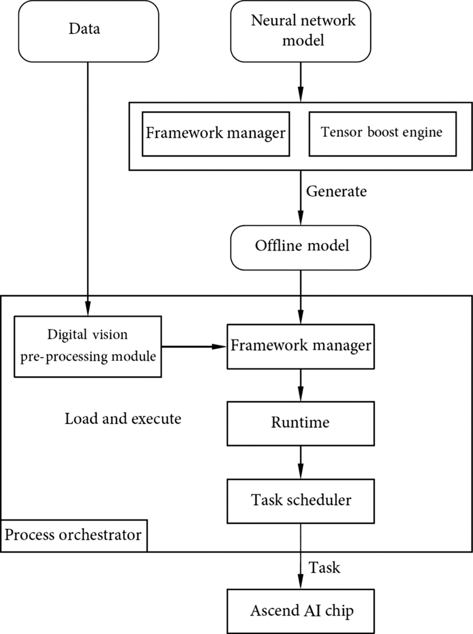
Each of these functional blocks has its specialty: the process orchestrator is responsible for implementing the neural network on the Ascend AI processor, coordinating the effective process of the entire neural network, and controlling the loading and execution of the offline model. The DVPP module performs data processing and modification to meet the format requirement. As a neural network operator, TBE provides a powerful computing operator for the neural network model. The framework manager uses the original neural network model to create the form supported by the Ascend AI processor and integrates the model with the Ascend AI processor to guide the running of the neural network and further improve the performance. The Runtime provides various resource management channels for the task delivery and allocation of the neural network. As a task driver for hardware execution, the TS provides specific target tasks for the Ascend AI processor. The Runtime and TS interact together to form a system of neural network tasks flowing to the hardware resources and monitor and distribute effectively different types of execution tasks in real time. In short, the entire neural network software flow provides a software and hardware combination and complete implementation process for the Ascend AI processor, contributing to the development of the relevant application ecosystem.
4.2.1: Process orchestrator (matrix)
4.2.1.1: Functions
The Ascend AI processor divides the network execution layers into basic execution units to obtain the granular computing engine (Engine). Each engine performs specific operations on data during process orchestration, such as classifying images, preprocessing input data, and outputting image data. In short, the computing engine is customized by developers to perform the required functions.
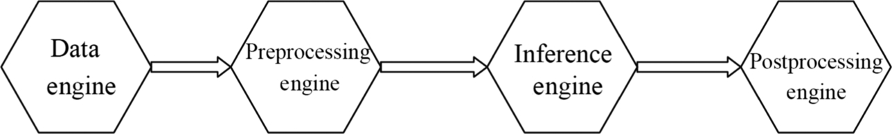
Generally, through the unified invoking of the process orchestrator, the entire deep neural network application includes four engines: data engine, preprocessing engine, model inference engine, and postprocessing engine. The data engine prepares the dataset (for example, MNIST dataset [4]) required by the neural network and processes the corresponding data (such as image filtering) as the data source of the subsequent computing engines. Generally, input media data needs to be preprocessed to meet the computing requirements of the Ascend AI processor. The preprocessing engine preprocesses the media data, performs operations such as image and video encoding and decoding, and format conversion. In addition, all functional modules of the DVPP need to be called by the process orchestrator. The model inference engine needs to be used when data flows are based on neural network inference. The model inference engine mainly uses the loaded model and the input data flow to complete the feed-forward calculation of the neural network. After the model inference engine outputs the result, the postprocessing engine performs subsequent processing on the output of the model inference engine, for example, adding a frame and adding a label to the image recognition. The four engines can be used to construct multiple types of neural network applications and implement service functions based on the neural network in a combination of computing engines. The computing engine integrates functions similar to operators, abstracts the functional structure of the neural network from a higher level, and brings concise basic functional modules for the specific application development of the neural network, accelerating the development process of the neural network application.
In addition to engine encapsulation of the execution layer, the Ascend AI processor performs offline model conversion on the neural network model, so that it can be executed on the Ascend AI processor in the form of an offline model. The neural network model can be converted to an offline model by using the Offline Model Generator. The offline model includes the dependency of operators on the network and the training weight information. These dependencies and weight information constitute a neural network calculation diagram in essence. The offline model can run independently on the hardware, so that the processor can completely separate from the basic neural network open-source framework when completing the specific inference task, thereby saving a lot of resource overhead. The offline model can also reduce the size of the model, save storage space, and adapt to lightweight applications by means of quantization and compression. In addition, the offline model is closely related to the hardware and is highly optimized based on the hardware of the Ascend AI processor. In this way, performance and efficiency are greatly improved.
In fact, the process of implementing a neural network offline model is achieved through the orchestration and design of the computing engine process. After the orchestration is complete, the computing engine flowchart is generated. Fig. 4.3 shows a typical example. In the computing engine flowchart, each data processing node is a computing engine. Data flows are processed and calculated based on the orchestrated paths, and the results are output. The final output of the entire flow chart is the result generated by the corresponding neural network. Two adjacent computing engine nodes establish a connection based on the configuration file in the flowchart of the computing engine. The actual data between nodes flow according to the node connection defined by a specific network model. After node attributes are configured, data is imported to the start node of the computing engine flowchart to start the running process of the entire computing engine.
As the process orchestrator of the entire neural network, which is between the L1 processor enabling layer and the L3 application enabling layer, it provides unified standard intermediate interfaces for multiple operating systems (such as Linux and Android), in addition, it is responsible for establishing, destroying, and reclaiming computing resources.
During the process of creating a computing engine flowchart, the process orchestrator completes the computing engine flowchart creation based on the configuration file of the computing engine. Before execution, the process orchestrator provides input data. If the form of video input data does not meet the processing requirement, the DVPP module may be invoked by using a corresponding programming interface to perform data preprocessing. If the data meets the processing requirements, the Offline Model Executor is invoked to perform inference calculation. During the execution, the process orchestration apparatus has multiple node scheduling and multiprocess management functions. It is responsible for computing the running of the process on the device, guarding the computing process, and collecting and summarizing related execution information. After the model is executed, it provides the application on the active node with the functionality of obtaining the output result.
The Ascend AI processor uses the computing engine and process orchestrator to orchestrate and execute the computing engine diagram. The process orchestrator provides four common computing engines, which effectively enables multiple neural network offline models to be object oriented and process based. In addition, the data flow control is enhanced, so that the execution of different models has a general process template for development and design. The concept of computing engine also allows data flows and computing flows to be centrally managed in the flowchart.
4.2.1.2: Application scenarios
The Ascend AI processor can set up a hardware platform with different dedicated hardware for different services. Therefore, based on the collaboration between the device and host, there are two common application scenarios: Accelerator and Atlas DK. The applications of the process orchestrator in these two typical scenarios are different.
Acceleration card form
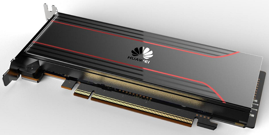
In an acceleration card application scenario, as shown in Fig. 4.4, a PCIe [5] card based on an Ascend AI processor is mainly oriented to a data center or an edge server scenario. It is a dedicated acceleration card for accelerating neural network computing. The PCIe accelerator card supports multiple types of data precision. Compared with other similar acceleration cards, the PCIe accelerator card provides more powerful computing power for the calculation of the neural network. In the accelerator scenario, a host needs to be connected to the accelerator card, and the host is a server or a personal computer that supports the PCIe card. The host invokes the neural network computing capability of the acceleration card to perform corresponding processing.
As shown in Fig. 4.5, the process orchestrator function in the acceleration card scenario is implemented by three subprocesses: process orchestration agent subprocess (Matrix Agent), process orchestration daemon (Matrix Daemon), and process orchestration service subprocess (Matrix Service). The process orchestration agent subprocess runs on the host, controls and manages the data engine and postprocessing engine, processes data interaction with the host application, controls the application and communicates with the processing on the device. The process orchestration daemon and service subprocesses run on the device. The process orchestration daemon process creates processes on devices based on the configuration file, starts the process orchestration process on the device, and manages the process orchestration process. After the calculation is complete, the process orchestration process is released and resources are reclaimed. The process orchestration service subprocess starts and controls the preprocessing engine and model inference engine on the device. It controls the preprocessing engine to call the programming interface of the DVPP module to implement the video and image data preprocessing function. The process orchestration service subprocess can also call the AI model manager programming interface in the Offline Model Executor to load and inference offline models.
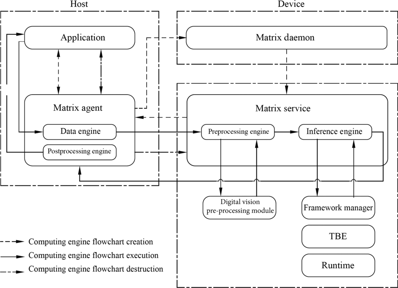
Fig. 4.5 shows the process of calculating the offline model of the neural network through the process orchestrator. The process consists of three steps: creating a computing engine flowchart, executing a computing engine flowchart, and destroying a computing engine. The process of creating a computing engine is to use the computing engine of different functions to orchestrate the execution process of the neural network. The computing engine flowchart is used to calculate and implement the neural network function based on the defined flowchart. The process of destroying the computing engine is used to release the system resources occupied by the computing engine after all computing is complete.
The process of executing an application in the system is as follows: first, the application program invokes a subprocess of the host’s process orchestration agent to orchestrate the computing engine flowchart according to a precompiled configuration file of the corresponding neural network, creates an execution process of it and defines a task of each computing engine. Then, the computing engine orchestration unit uploads the offline model file and the configuration file of the neural network to the process orchestration daemon process on the device, and then the process orchestration service subprocess of the device initializes the engine. The process orchestration service subprocess controls the model inference engine to invoke the initialization interface of the AI model manager to load the offline model of the neural network.
After the offline model is loaded, the process orchestration agent subprocess on the host is notified of the application data input. The application directly sends the data to the data engine for processing. If the input is media data and does not meet the calculation requirements of the Ascend AI processor, the preprocessing engine starts immediately and calls the interface of the DVPP module to preprocess media data, such as encoding, decoding, and scaling. After the preprocessing is complete, the preprocessing engine sends the data to the model inference engine. In addition, the model inference engine invokes the processing interface of the AI model manager to combine the data with the loaded offline model to complete inference calculation. After the output result is obtained, the model inference engine invokes the data sending interface of the process orchestration unit to return the inference result to the postprocessing engine, which completes the postprocessing operation of the data, and finally returns it to the application program by using the process orchestration unit, then completes the flowchart of executing the computing engine.
After all engine data is processed and returned, the application notifies the process orchestration agent subprocess to release the hardware resources of the data engine and postprocessing engine. The process orchestration agent subprocess instructs the service subprocess to release resources of the preprocessing engine and the model inference engine. After all, resources are released, the computing engine flowchart is destroyed. The process orchestration agent subprocess instructs the application program to perform the next neural network execution.
The three software units implement the computing engine process in an orderly manner and work together to implement the function application of a neural network offline model on the Ascend AI processor.
Developer board form
In the developer board scenario, Huawei launches the Atlas developer suite (Atlas200 Developer Kit, Atlas 200DK), as shown in Fig. 4.6, including the hardware of a developer board that uses the Ascend AI processor as the core. The developer board provides the kernel functions of the Ascend AI processor through the peripheral interfaces on the board. This facilitates the control and development of the processor from the external. It can easily and intuitively display the neural network processing capability of the Ascend AI processor. Therefore, the developer board based on the Ascend AI processor can be widely used in different AI fields and is also the main hardware on edge devices in the future.

In the developer board environment, the control function of the host is integrated into the developer board. Therefore, the process orchestrator has only one software unit to run the process, which includes the subprocess functions of the host process orchestration agent, device process orchestration service, and process orchestration daemon process in the acceleration card scenario, as shown in Fig. 4.7.
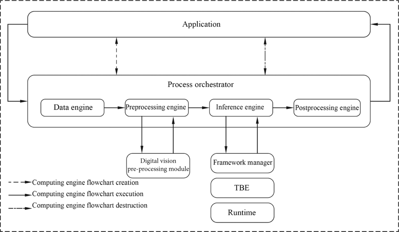
In this case, as the functional interface of the Ascend AI processor, the process orchestrator function implements data interaction and commands between the computing engine flowchart and applications. The process orchestrator creates a computing engine flowchart based on the configuration file of the computing engine process to orchestrate, control, and manage processes. After the calculation is complete, the process orchestrator releases the computing engine flowchart and reclaims resources. During preprocessing, the process orchestrator invokes the interface of the preprocessing engine to perform media preprocessing. During the inference process, the process orchestrator can also invoke the programming interface of the AI model manager to load and inference offline models. In the developer board application scenario, the process orchestrator orchestrates the implementation process of the entire computing engine flowchart and does not need to interact with other devices.
Similarly, in the developer board scenario, the offline model of the neural network uses the process orchestrator to perform inference calculation. The process is also divided into three main steps: creating, executing, and destroying a computing engine flowchart, as shown in Fig. 4.7.
Specifically, the application invokes the process orchestrator, creates a flowchart of the computing engine according to the network model, and initializes the computing engine. During initialization, the model inference engine loads the model through the initialization interface of the AI model manager to complete the creation of the computing engine flowchart. Then, the data is imported to the data engine. If the media data format does not meet the requirements, the preprocessing engine performs preprocessing. Then, the model inference engine invokes the AI model manager in the Offline Model Executor to perform inference calculation. After the calculation is complete, the model inference engine invokes the data output interface provided by the process orchestrator to return the inference result to the postprocessing engine, which returns the reasoning result to the application program through the callback function to complete the execution of the calculation engine flowchart. Finally, after the program calculation is complete, the process orchestrator destroys the computing engine flowchart and releases resources, then completes implementation of the neural network function in the developer board scenario.
4.2.2: Digital vision pre-processing module
As the encoding, decoding, and image conversion module in the whole software flow execution process, the DVPP module plays the assistant role for the neural network. Before the video or image data from the system memory and network enters the computing resources of the Ascend AI processor, the DaVinci architecture has a fixed format requirement for the input data. If the data does not meet the input format and resolution requirements specified in the architecture, the digital vision processing module needs to be invoked to convert the format so that the subsequent neural network calculation steps can be performed.
4.2.2.1: Functional architecture
The DVPP module provides six modules: video decoding (VDEC) module, video encoding (VENC) module, JPEG decoding (JPEGD) module, JPEG encoding (JPEGE) module, PNG decoding (PNGD) module, and visual preprocessing (VPC) module. The video decoding module provides the video decoding function of the H.264/H.265, which decodes the input video streams and outputs images for scenarios such as video recognition. For the counterparts, the video encoding module provides the encoding function of the output video. For the output data of the vision preprocessing module or the raw input YUV [6] format data, the video encoding module encodes and outputs the H.264/H.265 video, so as to directly play and display the video. This function is commonly used in high-speed data transmission scenarios such as cloud games and simulated mobile phone service. For pictures in JPEG format, the corresponding encoding and decoding module is also available. The JPEG decoding module decodes the JPEG picture, converts the original JPEG picture into YUV data, and preprocesses input data of the neural network. After the image processing is complete, the JPEG encoding module needs to be used to restore the processed data in JPEG format for training of the neural network and postprocessing of the inference output data. When the input picture is in PNG format, the flow orchestrator needs to invoke the PNGD decoding module to decode the picture and output the PNG picture in RGB format to the Ascend AI processor for training or inference calculation. In addition to the encoding and decoding modules for video and image formats, the DVPP module also provides other functions such as format conversion (for example, conversion from YUV/RGB format to YUV420 format), resizing, and cropping.
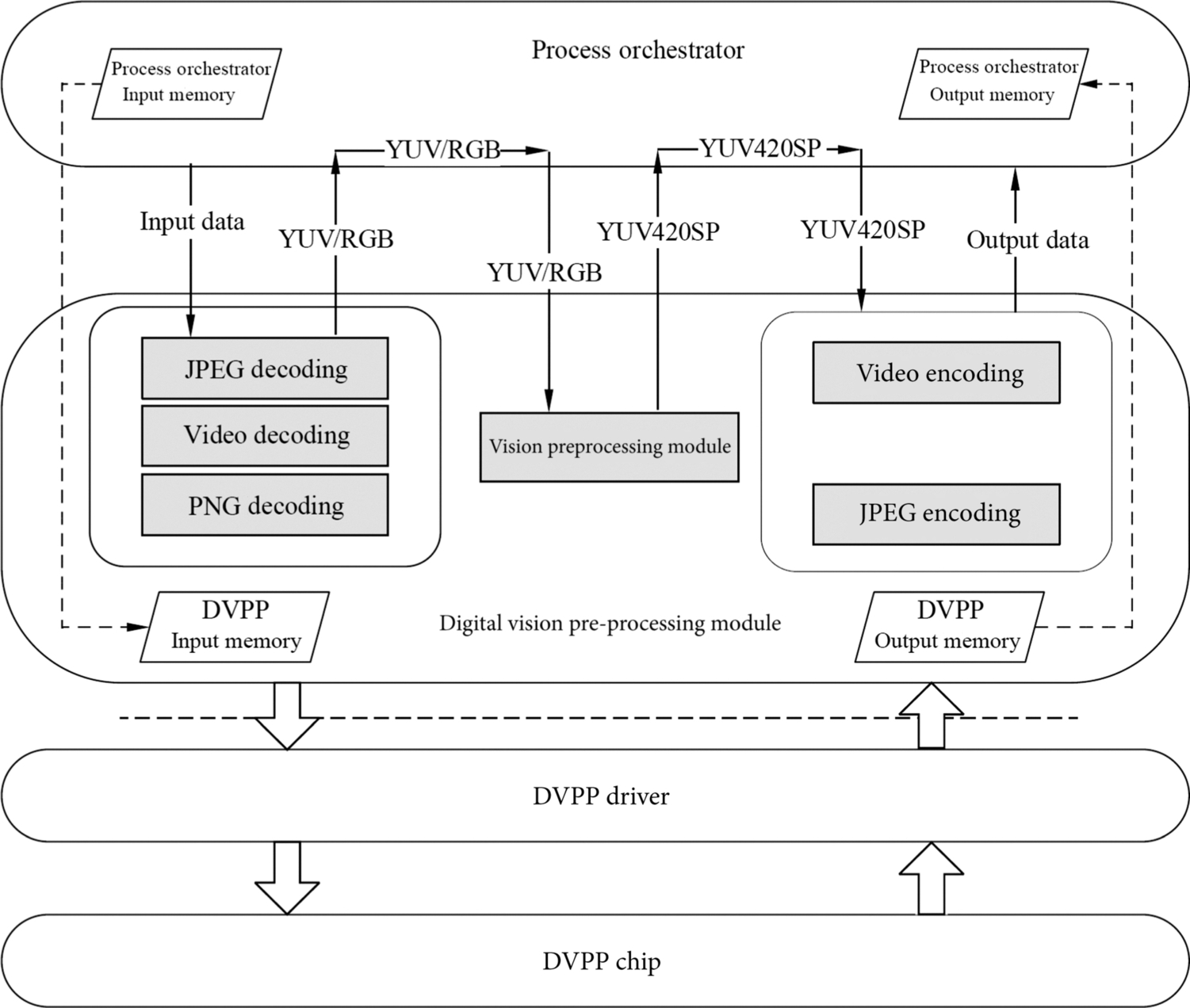
The execution process of the digital visual processing module is shown in Fig. 4.8 and needs to be completed by a process orchestrator, a digital vision processing module, a DVPP driver, and a DVPP hardware module. The top layer of the framework is the process orchestrator, which is responsible for scheduling the functional modules in the DVPP for processing and managing data flows. The digital vision processing module is located at the upper layer of the functional architecture and provides a programming interface for the process orchestrator to invoke the video or image processing module. Through these interfaces, parameters related to the encoding/decoding or vision preprocessing module can be configured. The DVPP driver is located in the middle and lower layers of the functional architecture and is closest to the hardware module of the DVPP. It is responsible for device management, engine management, and engine module driver. The driver allocates the corresponding DVPP hardware engine according to the tasks delivered by the digital vision processing module and reads and writes the registers in the hardware module to complete other hardware initialization. The bottom layer is the real hardware computing resource DVPP module group. It is a dedicated accelerator independent of other modules in the Ascend AI processor. It is responsible for executing the encoding, decoding, and preprocessing tasks corresponding to images and videos.
4.2.2.2: Preprocessing mechanisms
When the input data enters the data engine, if the engine detects that the data format does not meet the processing requirements of the subsequent AI Core, the DVPP module can be enabled to perform data preprocessing. The data flow shown in Fig. 4.8 is taken as an example. First, the process orchestrator moves the data from the memory to the buffer of the DVPP module for caching. According to the format of the specific data, the preprocessing engine completes parameter configuration and data transmission through the programming interface provided by the digital vision processing module. After the programming interface is started, the digital vision processing module transfers the configuration parameters and the original data to the driver. The DVPP driver invokes the PNG or JPEG decoding module for initialization and task delivery. In this case, the PNG or JPEG decoding module starts the actual operation to decode the picture and obtain the YUV or RGB data to meet the subsequent processing requirements.
After the decoding is complete, the process orchestrator uses the same mechanism to continue to invoke the DVPP module to convert the image into the YUV420SP format, because the YUV420SP data storage efficiency is high and the occupied bandwidth is small. Therefore, more data can be transmitted under the same bandwidth to meet the powerful computing throughput requirement of the AI Core. In addition, the DVPP module can also crop and resize images.
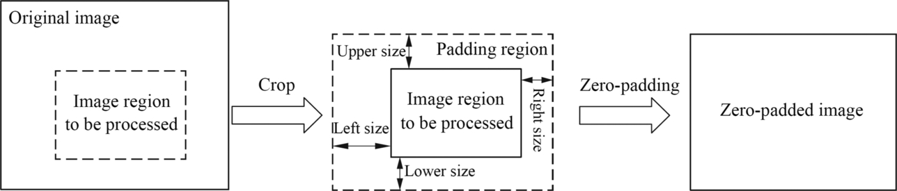
A typical image crop and zero-padding operation are shown in Fig. 4.9. The vision preprocessing module extracts the part of the to-be-processed image from the original image, and then performs zero padding, so as to retain the edge feature information during the calculation of the convolutional neural network. The zero-padding operation requires four padding sizes namely, upper, lower, left, and right. The image edge is expanded in the zero areas, and finally, a zero-padded image that can be directly calculated is obtained.
After a series of preprocessing, the image data that meets the format requirements will enter the AI Core for the required neural network calculation under the control of the AI CPU. After that, the output image data is encoded by the JPEG encoding module. After encoding, the data is stored in the buffer of the DVPP module. The process orchestrator obtains the data for subsequent operations, releases DVPP of computing resources, and reclaims the cache.
During the preprocessing, the process orchestrator implements functions of different modules. As a customized data supply module, the DVPP module uses a heterogeneous and dedicated processing method to quickly transform image data and provides sufficient data sources for AI Core, thereby satisfying a requirement of a large amount of data and a large bandwidth in a neural network calculation.
4.2.3: Tensor boost engine
Generally, in a neural network structure, an operator is used to form a network structure of different application functions. The TBE, being the arsenal of operators, provides the operator development capability for the neural network based on the Ascend AI processor, and constructs various neural network models by using the TBE operator written in the TBE language. In addition, the TBE provides encapsulation and invoking capabilities for operators. In the TBE, there is a neural network TBE standard operator library optimized by dedicated personnel. Developers can directly use the operators in the standard operator library to implement high-performance neural network calculations. In addition, the TBE also provides the fusion capability of the TBE operator, which opens a unique path for the optimization of the neural network.
4.2.3.1: Functional framework
The TBE provides the capability of developing customized operator based on TVM [7]. Through the TBE language and custom operator programming interface, the corresponding neural network operators can be developed. The structure of the TBE is shown in Fig. 4.10, which includes a domain-specific language (DSL) module, a scheduling (Schedule) module, an intermediate representation (IR) module, a compiler transfer (Pass) module, and a Code Generation (CodeGen) module.
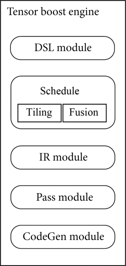
TBE operator development is divided into computing logic writing and scheduling development. The domain-specific language module provides the programming interface of the operator calculation logic and writes the calculation and scheduling process of the operator directly based on the domain-specific language. The operator calculation process describes the calculation methods and steps of the operator, and the scheduling process describes the planning of the data block and data flow direction. Each calculation is processed according to a fixed data dimension. Therefore, data dimension splitting needs to be performed on the operators executed on different computing units in the Ascend AI processor in advance. For example, the Cube Unit, the Vector Unit, and the operator executed on the AI CPU have different requirements for the input data dimension.
After defining the basic implementation process of the operator, you need to start the tiling (Tiling) submodule in the scheduling module, divide the data among the operator according to the scheduling description, and specify the data transfer process to ensure that the execution on the hardware is optimal. In addition to data dimension segmentation, the operator fusion and optimization capabilities of the TBE are also provided by the fusion (Fusion) submodule in the scheduling module.
After the operator is written, an IR needs to be generated for further optimization, and the IR module generates an IR by using an IR format similar to TVM. After the generation, the module needs to compile and optimize the modules for various application scenarios. The optimization modes include double-buffer (Double Buffer), pipeline (Pipeline) synchronization, memory allocation management, instruction mapping, and block adaptation Cube Unit.
After the operator is processed by the Pass module, the code generation module generates a temporary file of the C-like code. The temporary code file may generate an implementation file of the operator by using the compiler and may be directly loaded and executed by the Offline Model Executor.
To sum up, a complete customized operator uses the submodule of the TBE to complete the entire development process and provides the primitive operator calculation logic and scheduling description from the domain-specific language module. After the operator prototype is formed, the scheduling module performs data segmentation and operator fusion and enters the IR module to generate the IR of the operator. The Pass module performs compilation optimization such as memory allocation by means of the IR. Finally, the code generation module generates a C-like code for compiler. In the definition process of the operator, the TBE not only completes the operator writing but also completes the related optimization, which improves the execution performance of the operator.
4.2.3.2: Application scenarios
Fig. 4.11 shows the three application scenarios of the TBE. Generally, a neural network model implemented by using a standard operator in the deep learning framework has been trained by using a GPU or another type of neural network processor. If the neural network model continues to run on the Ascend AI processor, it is naturally expected to benefit the portability of the model and perform optimally without changing the original code. Therefore, the TBE provides a complete TBE operator acceleration library. The operator function in the library has a one-to-one mapping to common standard operators in the neural network. Meanwhile, the software stack provides a programming interface for the operator to use. Thus, it provides acceleration for various frameworks or applications in the upper-layer deep learning, and avoids the development of adaptation code for the bottom-layer adaptation of the Ascend AI processor.
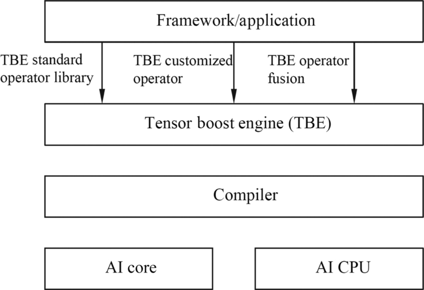
If a new operator appears in the neural network model construction, the standard operator library provided by the TBE may not meet the development requirements. In this case, you need to develop a customized operator in the TBE language. This development mode is similar to that of the CUDA C ++ on the GPU. In this way, more multifunctional operators can be implemented, and various network models can be flexibly compiled. The implemented operator is delivered to the compiler, and finally executes on the processor, revealing the acceleration capability of the AI Core or AI CPU.
In an appropriate scenario, the operator fusion capability provided by the TBE improves operator performance, and the neural network operator can perform multilevel cache fusion based on different levels of buffers so that the Ascend AI processor improves the on-chip resource utilization when the integrated operator is executed.
To sum up, because the TBE provides the operator development capability, the capability of standard operator invoking and operator fusion optimization, the Ascend AI processor can meet various function requirements in the actual neural network application, the network construction method is more convenient and flexible, and the fusion and optimization capabilities will also improve the running performance.
4.2.4: Runtime
Being the gateway of neural network software task flowing to the system hardware resources, the Runtime provides the resource management channel for the task allocation of the neural network. The Ascend AI processor runs in the application process space through the Runtime. It provides the following functions: memory (Memory) management, device (Device) management, stream (Stream) management, event (Event) management, and kernel (Kernel) execution.
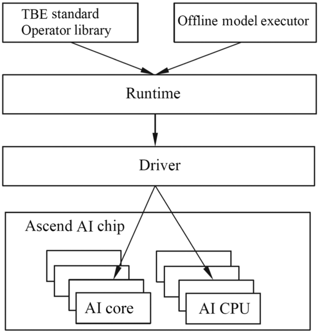
As shown in Fig. 4.12, the TBE standard operator library and Offline Model Executor provided by the upper layer of the Runtime for the TBE are shown in Fig. 4.12. The TBE standard operator library is the operator used by the Ascend AI processor to provide the neural network. The Offline Model Executor is used to load and execute the offline model. The lower layer of the Runtime is a driver and interacts with the Ascend AI processor at the bottom layer.
As shown in Fig. 4.13, the Runtime provides various invoking interfaces, such as memory interfaces, device interfaces, stream interfaces, event interfaces, and execution control interfaces. Different interfaces are controlled by the Runtime engine. The memory interface is used to apply for, release, and copy the HBM or DDR memory on the device, including data copy from the device to the host, from the host to the device, and from the device to the device. There are two types of memory copy: synchronous and asynchronous. Synchronous copy indicates that the next operation can be performed only after the memory copy is complete. Asynchronous copy indicates that other operations can be performed at the same time.
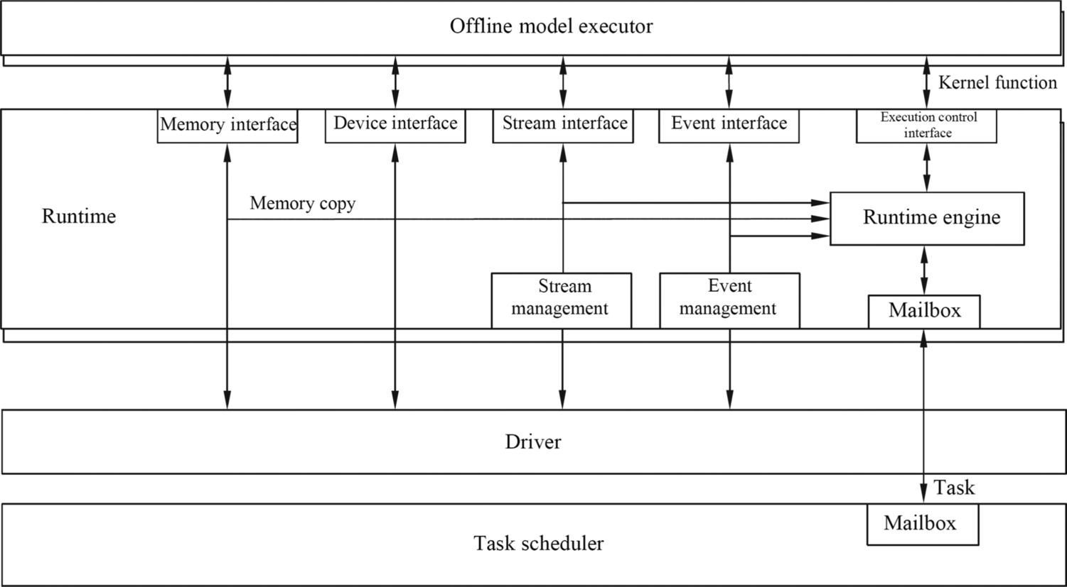
The device interface provides the function of querying the number and attributes of underlying devices and selecting and resetting the devices. After the offline model invokes the device interface and selects a specific device, all tasks in the model will be executed on the selected device. If a task needs to be dispatched to another device during the execution, the device interface needs to be invoked to select the device again.
The stream interface provides stream creation, release, priority definition, callback function setting, and event dependency definition and synchronization. These functions are related to task execution in the stream, and tasks in a single stream must be executed in sequence.
If multiple streams need to be synchronized, the event interface needs to be invoked to create, release, record, and define synchronization events to ensure that multiple streams are synchronized and output the final model result. The event interface is used to allocate the dependency between tasks or execution flows. It can also be used to mark the time during the program running and record the execution time sequence. During execution, the execution control interface is also used. The management engine executes the control interface and mailbox (Mailbox) to load the kernel functions and store asynchronous copies.
4.2.5: Task scheduler
The TS and the Runtime form a channeling system between software and hardware. During execution, the TS drives and supplies hardware tasks, provides specific target tasks for the Ascend AI processor, completes the task scheduling process with the Runtime, and returns the output data to the Runtime, which serves as a channel for task delivery and data backhaul.
4.2.5.1: Functions
The TS runs on the task scheduling CPU on the device side to distribute specific tasks assigned by the Runtime to the AI CPU. It can also allocate tasks to the AI Core through the hardware task Block Scheduler (BS) and return the execution result to the Runtime after the execution is complete. Generally, the TS processes the following transactions: AI Core tasks, AI CPU tasks, memory copy tasks, event recording tasks, event waiting tasks, cleanup and maintenance (Maintenance) tasks, and performance analysis (Profiling) tasks.
Memory copy is mainly performed in asynchronous mode. The event recording task records the event information. If a task is waiting for the current event, it can continue execution after the event record being completed, so that the stream is not blocked due to the event record itself. The event-waiting task could refer to: (1) if the waiting event has occurred, then the task is accomplished directly, or (2) if the waiting event has not yet occurred, then waiting task is put into the to-be-processed list, and all subsequent tasks of the waiting task in the same execution stream are paused, then resumes to process when it occurs.
After the task execution is complete, the maintenance task performs cleaning based on the respective parameters of each task and reclaims the computing resources. During the execution, you may need to record and analyze the computing performance. In this case, you need to use the performance analysis task to control the start and pause of the performance analysis operation.
Fig. 4.14 shows the functional framework of the TS. The TS is usually located at the device end and has the task scheduling CPU. The task scheduling CPU consists of the scheduling interface (Interface), scheduling engine (Engine), scheduling logic processing module, AI CPU scheduler, task block scheduler, system control (SysCtrl) module, performance analysis (Profile), and log (Log) module.
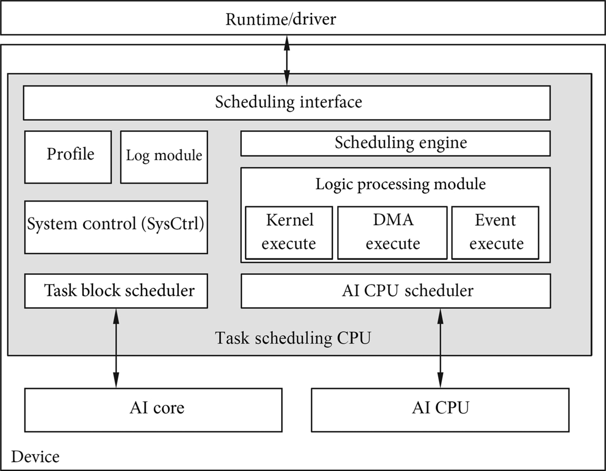
The task scheduling CPU implements communication and interaction with the Runtime and the driver through the scheduling interface. The task scheduling engine sends the task execution result to the task scheduling engine. The task scheduling engine is responsible for task organization, task dependency, and task scheduling control. The task scheduling engine manages the execution process of the task scheduling CPU. Based on the task type, the task scheduling engine divides tasks into three types: computing, storage, and control. The task scheduling engine distributes the tasks to different scheduling logic processing modules and starts specific kernel function tasks, storage tasks, and interflow event dependency management and scheduling.
The logic processing module is divided into a kernel execute module (Kernel Execute), a direct memory access module (DMA Execute), and an event execute module (Event Execute). The kernel executes module schedules and processes the computing task, implements the task scheduling logic on the AI CPU and AI Core, and schedules the specific kernel function. The direct memory access executes module implements the scheduling logic of the storage task, and schedules and processes the memory copy. The event execute module implements the scheduling logic of synchronization control tasks and implements the logic processing of interflow event dependency. After the scheduling logic of different types of tasks is processed, the corresponding control units start to perform hardware execution.
For the AI CPU task execution, the AI CPU scheduler in the task scheduling CPU uses software to manage the status of the AI CPU and schedule tasks. For the task execution of the AI Core, the task scheduling CPU distributes the processed task to the AI Core by using a separate task block scheduler hardware, and the AI Core performs the specific calculation, and the result of the calculation is returned by the task block scheduler to the task scheduling CPU.
During task scheduling, the system controls the system configuration and processor function initialization. The performance analysis and log modules monitor the entire execution process and record key execution parameters and detailed execution details. When the execution ends or an error occurs, performance analysis or error locating can be performed to provide a basis for detailed efficiency evaluation and correctness analysis of the execution process.
4.2.5.2: Scheduling process
During the execution of the offline model of the neural network, the TS receives specific execution tasks from the Offline Model Executor. The tasks depend on each other. Therefore, the TS needs to release the dependency relationship, perform task scheduling, distribute the tasks to the AI Core or AI CPU based on the specific task type and completes the calculation or execution of specific hardware. During task scheduling, a task is composed of multiple execution instructions (CMD). The TS interacts with the Runtime to schedule the entire task instruction. The Runtime executes on the CPU of the host, the instruction queue is located in the memory of the device, and the TS delivers the specific task instruction.
Fig. 4.15 shows the scheduling process. First, the Runtime invokes the dvCommandOcuppy interface of the driver to enter the instruction queue, queries the available storage space in the instruction queue according to the tail information of the instruction, and returns the available instruction storage space address to the Runtime. After receiving the address, the Runtime fills the currently prepared task instruction into the storage space of the instruction queue and invokes the dvCommandSend interface of the driver to update the current tail information and the credit (Credit) information of the instruction queue. After receiving the new task instruction, the queue generates a doorbell interrupt and instructs the TS to add a task instruction in the instruction queue in the device memory. After receiving the notification, the TS enters the device memory, moves the task instruction to the buffer of the scheduler, and updates the header information of the instruction queue in the DDR memory of the device. Finally, the TS sends the instruction in the cache to the AI CPU or the AI Core for execution according to the condition.
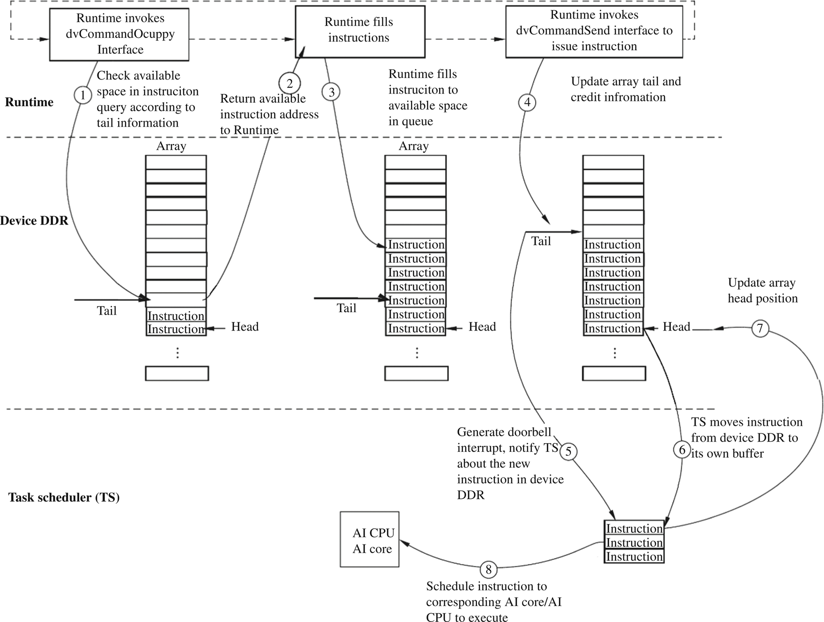
The structure of the software stack is basically the same as that of most accelerators. The Runtime, driver, and TS in the Ascend AI processor works closely together to distribute tasks to corresponding hardware resources and executes the tasks in an orderly manner. This scheduling process carries out tasks closely and orderly in the process of deep neural network calculation, which ensures the continuity and efficiency of task execution.
4.2.6: Framework manager
As the modeler and execution participant of the neural network in the implementation of the Ascend AI processor, the framework manager generates an executable offline model for the neural network in the neural network software flow. Before the neural network is executed, the framework manager and the Ascend AI processor combine to generate a high-performance offline model with hardware matching and streamline the process orchestrator and Runtime to deeply integrate the offline model and Ascend AI processor. When the neural network is executed, the framework manager together with the process orchestrator, Runtime, TS, and underlying hardware resources, combines the offline model, data, and the DaVinci architecture, and optimizes the execution process to obtain the application output of the neural network.
4.2.6.1: Functional framework
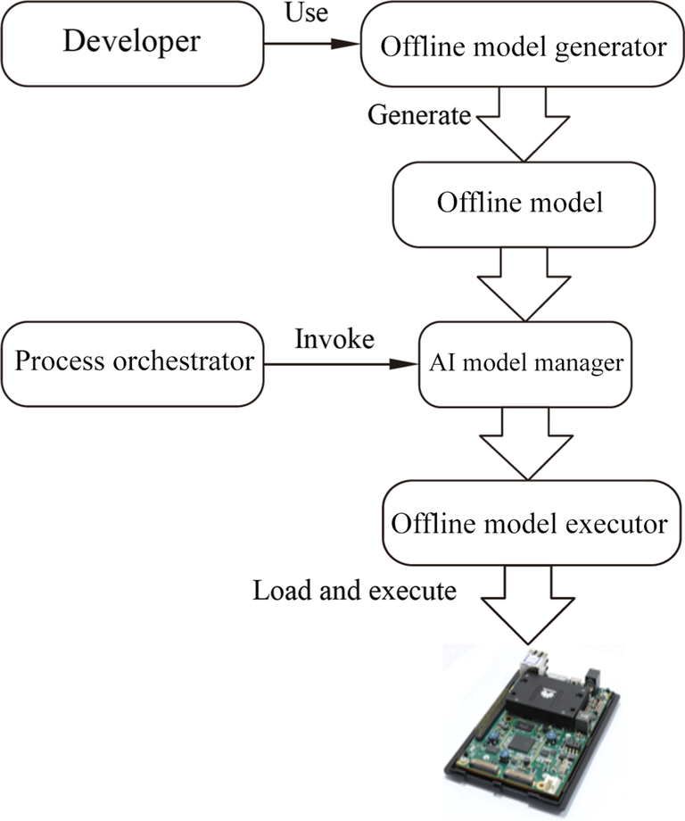
The framework manager consists of three parts: Offline Model Generator (OMG), Offline Model Executor (OME), and AI Model Manager, as shown in Fig. 4.16. Developers use the Offline Model Generator to generate an offline model and save the file with the suffix of om. Then, the process orchestrator in the software stack invokes the AI model manager in the framework manager to start the Offline Model Executor, load the offline model to the Ascend AI processor, and complete the offline model execution through the entire software stack. From the birth of the offline model to the loading and entering to the Ascend AI processor hardware until the last function operation, the offline framework manager always plays a management role.
4.2.6.2: Offline model generation
Taking the convolutional neural network as an example, the network model is first constructed under the deep learning framework and trained on the original data. And then the Offline Model Generator converts the original model and generates the optimized offline model, by performing operator scheduling optimization, weight data rearrangement and compression, and memory optimization. The Offline Model Generator is used to generate an offline model that can be efficiently executed on the Ascend AI processor.
Fig. 4.17 shows the principle of the Offline Model Generator. After receiving the original model, the Offline Model Generator performs model parsing, quantization, compilation, and serialization on the convolutional neural network model. The steps are described as follows:
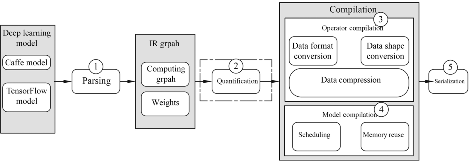
Parsing
During the parsing process, the Offline Model Generator supports the parsing of original network models in different frameworks, abstracts the network structure and weight parameters of the original model, and redefines the network structure by using the unified intermediate graph (IR Graph). The intermediate graph consists of a compute node and a data node. Compute node consists of TBE operators with different functions. The data node receives different tensor data and provides various input data for the entire network. This intermediate graph is composed of computing graphs and weights, covering all the original model information. The intermediate graph sets up a bridge between the deep learning framework and the Ascend AI software stack. In this way, the neural network model constructed by the external framework can be easily converted into the offline model supported by the Ascend AI processor.
Quantification
As shown in Fig. 4.18, an intermediate graph is generated after the parsing is complete. If the model needs to perform quantization processing, it may be performed by using an automatic quantization tool based on the structure and weight of the intermediate graph. In the operator, the weight and the offset can be quantized. During the offline model generation, the quantized weight and offset are stored in the offline model. During inference calculation, the quantized weight and offset can be used to calculate the input data, and the calibration set is used to train the quantization parameter in the quantization process, so as to ensure the quantization precision. If no quantization is required, the offline model is directly compiled to generate an offline model.
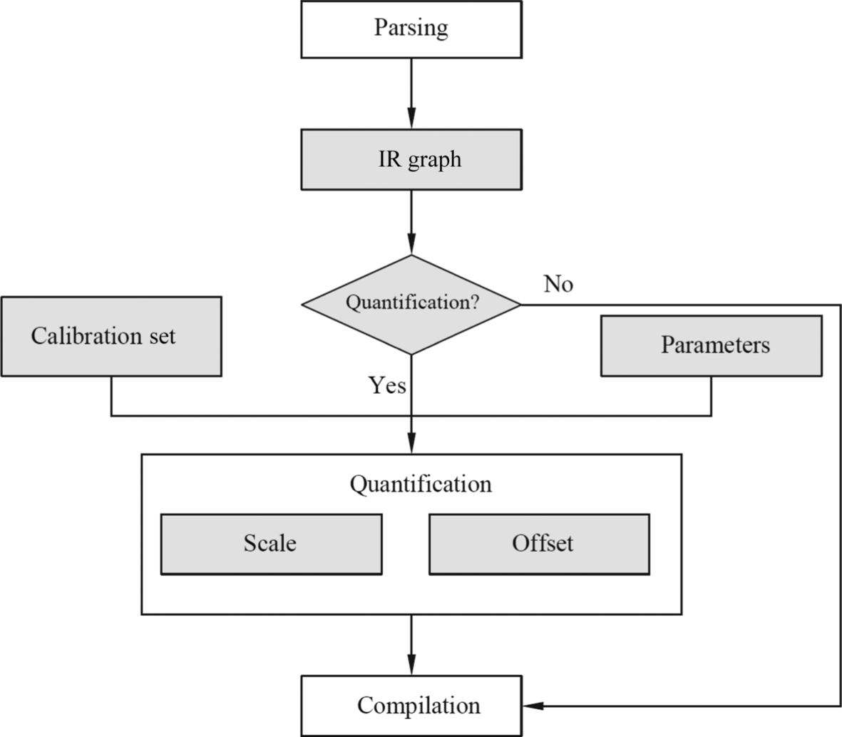
The quantization mode is divided into data offset quantization and nonoffset quantization. The quantization scale (Scale) and the quantization offset (Offset) parameters need to be output. In the data quantization process, when no offset is specified, the quantization scale of the quantized data is calculated by using the nonoffset mode. If the specified data offset is quantized, the data uses the offset mode. In this case, the quantization scale and offset of the output data are calculated. In the weight quantization process, because the weight has a high requirement on the quantization precision, the nonoffset mode is always used. For example, INT8-type quantization is performed on the weight file according to the quantization algorithm, so that the INT8 weight and the quantization degree may be output. In the process of offset quantization, the FP32-type offset data can be quantized into INT32-type data output according to the quantization degree of weight and the quantization degree of the data.
You can perform quantization operations when there are higher requirements for the size and performance of the model. In the offline model generation process, the high-precision data is quantized to the low-bit data, so that the final offline model is lighter, thereby saving the network storage space, reducing the transmission delay, and improving the operation efficiency. In the quantization process, because the model storage size is greatly influenced by parameters, the Offline Model Generator focuses on the quantization of the convolution operator, full connection operator, and depth separable convolution (ConvolutionDepthwise).
Compilation
After the model is quantified, you need to compile the model. The compilation consists of two parts: operator compilation and model compilation. The operator compilation provides the specific implementation of the operator. The model compilation associates the operator model with the aggregation connection to generate the offline model structure.
- Operator compilation
Operator compilation is used to generate operator-specific offline structures. Operator generation consists of three processes: input tensor description, weight data conversion, and output tensor description. The input tensor description calculates the input dimension and memory size of each operator and defines the form of operator input data in the Offline Model Generator. In the weight data conversion, the weight parameters used by the operator are processed such as data format (for example, conversion from FP32 to FP16), shape conversion (such as fractal rearrangement) and data compression. The output tensor description calculates the output dimension and memory size of the operator.
Fig. 4.19 shows the operator generation process. During operator generation, the interface of the TBE operator acceleration library is used to analyze and determine the shape of the output data. The TBE operator acceleration library interface can also convert the data format. The Offline Model Generator receives the intermediate graph generated by the neural network and describes each node in the intermediate graph, and parses the input and output of each operator one by one. The Offline Model Generator analyzes the input data source of the current operator, obtains the operator type directly connected to the current operator in the previous layer, accesses the operator library through the interface of the TBE operator acceleration library, searches for the output data description of the source operator, and returns the output data information of the source operator to the Offline Model Generator as the description of the input tensor of the current operator. Therefore, the output information of the source operator can be used to obtain the description of the input data of the current operator.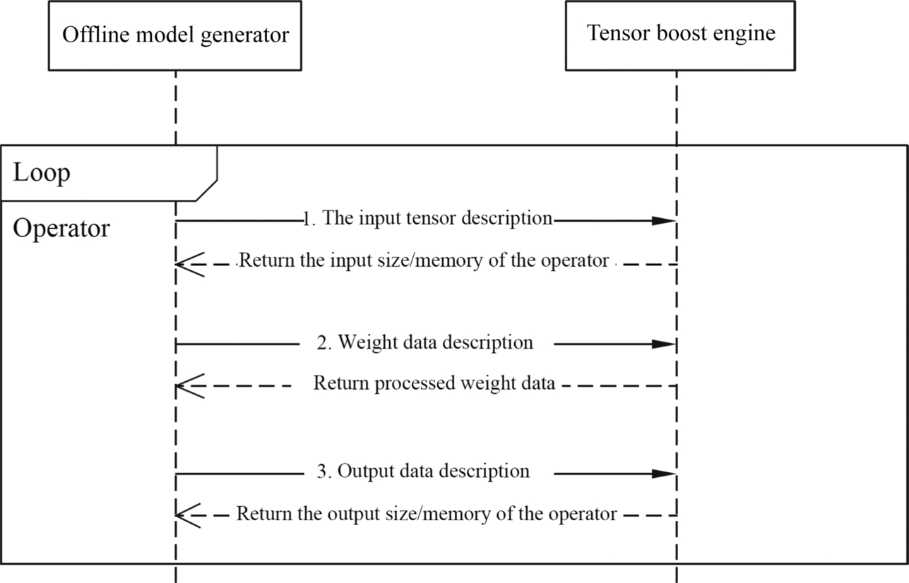
Fig. 4.19 Operator generation process.
If the node in the intermediate graph is not an operator but a data node, the input tensor description is not required. If the operator has weight data, such as the convolution operator and full connection operator, the weight data needs to be described and processed. If the input weight data type is FP32, the Offline Model Generator needs to invoke the type conversion (ccTransTensor) interface to convert the weight to the FP16 data type to meet the data-type requirements of the AI Core. After the type conversion is complete, the Offline Model Generator invokes the shape setting (ccTransFilter) interface to perform fractal rearrangement of the weight data, so that the input shape of the weight can meet the format requirement of the AI Core. After obtaining the weight of a fixed format, the Offline Model Generator invokes the compression optimization (ccCompressWeight) interface provided by the TBE to compress and optimize the weight, reduce the weight storage space, and make the model more lightweight. After the weight data is converted, the weight data that meets the calculation requirement is returned to the Offline Model Generator.
After the weight data is converted, the Offline Model Generator also needs to describe the output data information of the operator and determine the output tensor form. For high-level complex operators, such as convolution operators and pooling operators, the Offline Model Generator can directly use the computing interface provided by the TBE operator acceleration library. For example, the convolution operator corresponds to the ccGetConvolution2dForwardOutputDim interface, and the pool operator corresponds to the ccGetPooling2dForwardOutputDim interface, and the output tensor information of the operator is obtained by combining the input tensor information and weight information of the operator. If a low-level simple operator, such as an addition operator, is directly used to determine the output tensor form by using the input tensor information of the operator, then it is finally sent into the Offline Model Generator. According to the foregoing running process, the Offline Model Generator traverses all operators in the intermediate network diagram, cyclically executes the operator generation steps, describes input and output tensor and weight data of all operators, completes the offline structure representation of the operator, and provides an operator model for the next model generation. - Model compilation
After the operator is generated during compilation, the Offline Model Generator also needs to generate a model to obtain the offline structure of the model. The Offline Model Generator obtains an intermediate graph, performs parallel scheduling analysis on the operator, splits multiple intermediate graph nodes, and obtains multiple streams formed by an operator and data input, where the stream may be regarded as an execution sequence of the operator. Nodes that do not depend on each other are directly allocated to different execution flows. If nodes in different execution flow depend on each other, the rtEvent synchronization interface is used to perform interflow synchronization. When the AI Core computing resources are sufficient, multiexecution flow splitting can provide multistream scheduling for AI Core, thereby improving the computing performance of the network model. However, if a large number of parallel tasks are processed by the AI Core, resource preemption is aggravated and performance is deteriorated. Generally, a single stream is used to process the network by default, which prevents congestion caused by concurrent execution of multiple tasks.
In addition, based on specific relationships of execution sequences of multiple operators, the Offline Model Generator may perform operator fusion optimization independent of hardware and memory reuse optimization operations. Based on the input and output memory information of the operator, the memory is reused, and the related multiplexing information is written into the model and operator description to generate an efficient offline model. These optimization operations can redistribute computing resources that are executed by multiple operators to minimize memory usage during running and avoid frequent memory allocation and release during running. In this way, the minimum memory usage and data migration frequency can be used to implement multiple operators, improving performance, in addition, the requirements for hardware resources are reduced.
Serialization
The offline model generated after compilation is stored in the memory and needs to be serialized. In the serialization process, the signature and encryption functions are provided for the model file to further encapsulate and protect the offline model. After serialization, the offline model can be exported from the memory to external files for the remote Ascend AI processor to invoke and execute.
4.2.6.3: Loading offline model
After the Offline Model Generator in the framework manager completes the offline model generation, the Offline Model Executor loads the model to the Runtime and integrates with the Ascend AI processor to perform inference calculation. In this process, the Offline Model Executor plays the main model execution function. Fig. 4.20 shows the process of loading an offline model. First, the process orchestrator, as the entry for interaction between applications and software stacks, provides the management capability for the execution process of inference tasks, divides the process that needs to be completed in the entire offline model into the engine of each execution phase and invokes the loading interface of the AI model manager to initialize the process of the device and load the offline model. Then, the Offline Model Executor is started to load the offline model, deserialize the offline model file, decode the executable file, invoke the storage interface of the execution environment to apply for memory, and copy the weight of the operator in the model to the memory. In addition, resources such as the model execution handle, execution flow, and event of the Runtime are applied for, and resources such as execution flows are bound to the corresponding models one by one. An execution handle executes a neural network computing graph. An execution handle can have multiple execution flows. Different execution flows contain AI Core or AI CPU computing tasks. A task is performed by a kernel function on AI CPU or AI Core, and events refer to the synchronization operations between different execution flows.
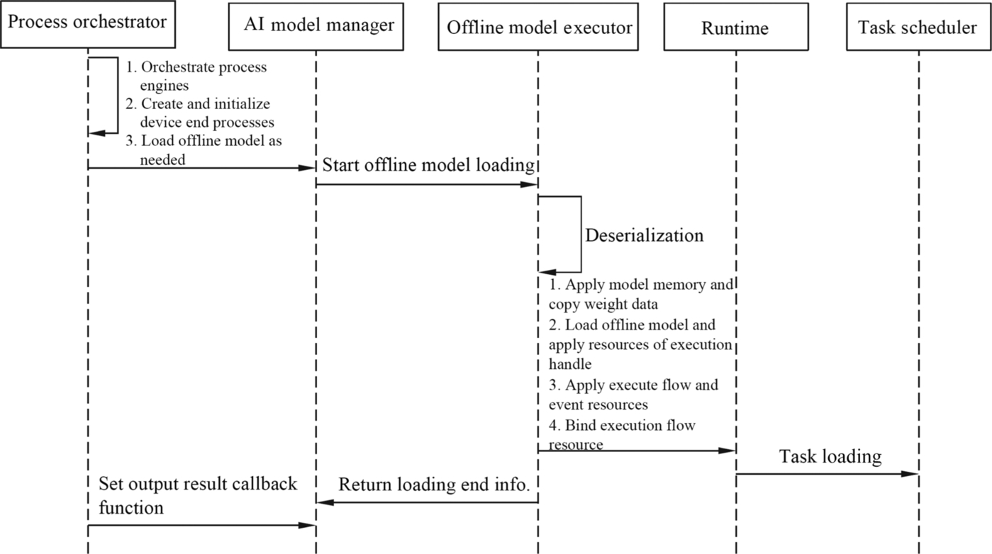
After a model is calculated, all operators in the offline model need to be traversed and the task information is updated. The Offline Model Executor invokes the running manager interface to deliver the task to the TS. Then, the Offline Model Executor returns the loading end information to the AI model manager, then, the process orchestrator sets the output result callback function to obtain the execution result. So far, the offline executor completes the loading process of the offline model, and the next step can directly perform inference calculation. This loading process is equivalent to adapting the model to the Ascend AI processor. The hardware resource and the operator in the offline model are planned in a coordinated manner. In this way, the offline model is executed in an orderly manner in subsequent execution, and the prespeed capability is provided for inference calculation.
4.2.6.4: Offline model inference
After the offline model is loaded, the inference function of the model can be implemented. Because the offline model is essentially a neural network model, corresponding functions, such as image recognition, are performed in the inference process. During the generation and loading of the offline model, no specific data to be processed is used. Only the software stack is used to construct, orchestrate, optimize, encapsulate, and perform hardware adaptation for the operator and calculation process in the model. In the specific inference execution process, the specific input data is read to drive the execution and output the result.
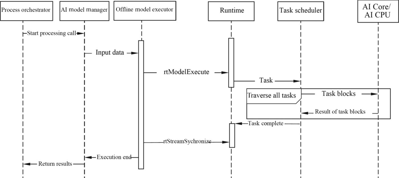
Fig. 4.21 shows the offline model inference process. When an application needs to process data, it prepares data to be processed. The process orchestrator invokes the processing interface of the AI model manager to inject data into the Offline Model Executor. Then, the Offline Model Executor invokes the execution flow (rtModelExecute) interface of the Runtime to deliver multiple inference tasks in the execution flow to the TS. The TS splits the task into task blocks and delivers them to the AI Core or AI CPU for execution. After the tasks are completed, the TS returns the result. The task scheduler traverses the tasks in the execution flow, cyclically transmits the task blocks, and returns the execution result. After all the tasks are complete, the TS returns the result to the memory of the Runtime. When the task of multiple executions flows is calculated, the operator synchronization between multiple streams needs to be performed through the event record and event waiting interface in the Runtime, and the operator calculation is completed in an orderly manner. After all operators in a stream are invoked, the Offline Model Executor synchronizes the execution completion of all execution flows through the execution flow synchronization (rtStreamSychronize) interface of the Runtime. After all related execution flow tasks are completed, the final results of all result generation models are integrated. In this case, the Offline Model Executor notifies the AI model manager that the stream has been executed. Finally, the AI model manager invokes the preset output callback function to return the result of the offline model reasoning execution to the process orchestrator, which then sends the result to the application.
4.2.7: Application of neural network software flow
The overall process of application of the neural network software flow includes defining a neural network structure under the deep learning network framework, generating a neural network model, and transferring the neural network software flow to the Ascend AI processor for function implementation. Now the Inceptionv3 classification network is used as an example to show the practical application of the neural network software flow.
The Inceptionv3 [8] classification network is a convolutional neural network designed for image classification. Users can define the network structure and complete training in the Caffe deep learning framework provided by the neural network software flow. The network structure is saved through the prototxt format and the weight is saved in the caffemodel file. The structure of the Inceptionv3 classification network consists of the convolution layer, pooling layer, and fully connected layer. The input data is processed layer by layer and fed forward.
After the original Inceptionv3 network model is created, the offline model conversion is required. The Offline Model Generator and TBE in the neural network software flow are used to generate the original model in offline mode. You can invoke the running program of the Offline Model Generator through the command line, and then the Offline Model Generator completes the model parsing, model compilation, and serialization in sequence to generate the final offline model. If the network needs to be quantified, the Offline Model Generator can also quantify the model parameters.
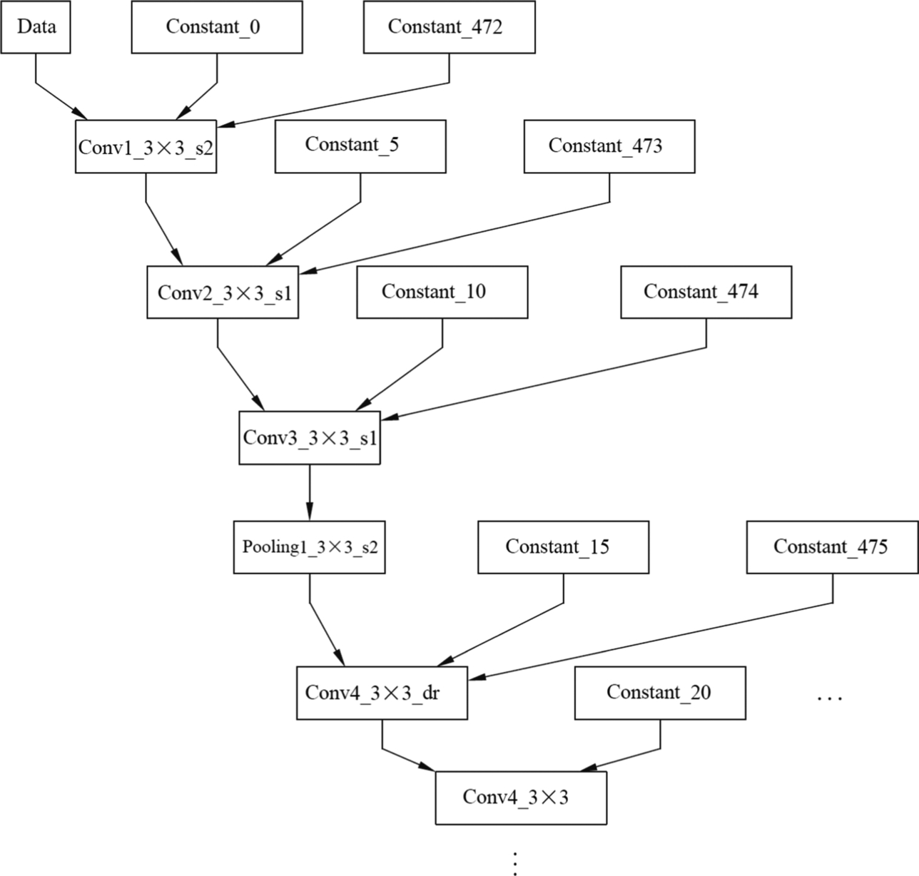
After the offline model conversion is complete, the offline model can be obtained, and the execution sequence of operators in the model and related data dependency can be presented in a directed loop-free diagram. As shown in Fig. 4.22, the offline model structure of the InceptionV3 network is shown in Fig. 4.22. When the Caffe model is converted to an offline model, operator integration is performed, and the input data changes. In the original Caffe model, the default values are used for parameters such as step and convolution kernel. However, in the converted offline model, a constant (Const) node is used to represent input, and these constant nodes can receive parameters such as a convolution stride and convolution kernels, and pass the parameters into the model. In this way, a variable network parameter may be input according to a specific requirement, and the implemented function may be relatively flexible.
After the Inceptionv3 network offline model is generated, to enable the classification function of the Inceptionv3 network on the Ascend AI processor, the process orchestrator needs to create a computing engine flowchart and implement the Inceptionv3 network offline model by executing the flowchart of the computing engine. Therefore, you need to define the following four computing engines: the data engine, preprocessing engine, model inference engine, and postprocessing engine. Besides, it is needed as well to define the connection between four computing engines and the configuration file of node attributes.
Assuming that the network function is implemented on the developer board, the process orchestrator generates a flowchart of the computing engine based on the configuration of the computing engine and then invokes the initialization interface of the AI model manager to load the offline model of the Inceptionv3 network.
During offline model loading, the application program starts loading through the AI model manager through the process orchestrator, and then the Offline Model Executor deserializes the Inceptionv3 network offline model. After deserialization, the Offline Model Executor invokes the runtime interface to copy the weight to the memory, applies for hardware resources for the execution handle, execution flow, and event, and binds the hardware resources. After the resource configuration is complete, the operator in the model is mapped to the stream. Each stream completes the calculation submap of the corresponding operator and allocates events to the synchronization management of multiple streams. In addition, the Offline Model Executor invokes the runtime interface to map the tasks in the execution flow to the kernel functions on the AI Core or AI CPU and updates the execution information in the task. Each kernel function completes a specific task during the offline model execution. Finally, the Offline Model Executor calls the task interface in the Runtime to distribute the tasks in the model to the execution hardware. By now, the InceptionV3 network function has been split into tasks and matched with hardware resources. The InceptionV3 network offline model has been loaded, and the calculation engine flowchart has been created.
After the computing engine flowchart is created, execute the flowchart of the computing engine. The data engine receives images to be classified by the InceptionV3 network, and then the process orchestrator starts the preprocessing engine. The engine invokes the DVPP module through the DVPP interface to preprocess image data, including encoding, decoding, and scaling. The processed image data enters the model inference engine through the process orchestrator and starts inference calculation.
During inference calculation, the model inference engine invokes the interface of the AI model manager to start the inference calculation process. The preprocessed image data is transferred from the AI model manager to the Offline Model Executor. Then the Offline Model Executor invokes the interface in the Runtime to inject data configured during the loading process to the TS. After receiving the task, the TS schedules the hardware AI Core or AI CPU, and the task is executed by the hardware. All tasks in the execution flow are executed in sequence. Under the control of event synchronization, the output results of different streams are integrated and the final result is generated. In this case, the AI model manager returns the result of the classified image to the process orchestrator. Finally, the process orchestrator sends the result to the postprocessing engine, which then displays the classification result through the callback function.
After the classification result is output, the process orchestrator needs to be used to destroy the computing engine flowchart of the InceptionV3 network to release computing resources. To this end, the whole function implementation of the InceptionV3 network on the Ascend AI processor is completed.
This section uses the InceptionV3 classification network as an example. This section describes how to generate an offline model from the original network model, create a flowchart of the computing engine, and execute the flowchart of the computing engine. The execution process also experiences the loading and inference calculation of the offline model of the network, and finally the destruction of the flowchart of the computing engine. All of these are implemented based on the software modules provided by the Ascend AI software stack. The neural network software stream provides a perfect world for software to support the functions of various neural networks on the Ascend AI processor.
4.3: Development tool chain
If a worker wants to do something good, he must first sharpen his tools. The design of the Ascend AI software stack was deeply practiced, and various functional tools were developed to form a versatile tool chain. From the construction of neural networks, to offline model generation, to hardware-related execution, each link has some tools to assist.
In the process of building network execution, if there is no corresponding development tool, it requires a lot of manpower and energy in the development process, and each development requires human intervention, which increases the difficulty and cycle of development. The tool chain of the Ascend AI software stack will be processed by tools so that developers can focus on the performance mining of neural networks and promote the efficient application of the AI processor from the speed of process development.
4.3.1: Introduction to functions
All toolchains are integrated on the Mind Studio development platform. Mind Studio is a Huawei-based AI processor development toolchain platform that provides processor-based operator development, debugging, tuning, and third-party operator development capabilities, as well as network migration, optimization, and analysis capabilities. It brings great convenience for users to develop applications. Mind Studio provides developers with a variety of functions such as operator development, network model development, computation engine development, and application development through web pages:
- (1) For operator development, Mind Studio provides a full set of operator development and tuning capabilities to support the operation of analog operators in real-world processor runtime environments. The toolchain provided by Mind Studio can also be used for third-party operator development, which reduces the threshold for operator development, improves the efficiency of operator development and debugging, and effectively enhances product competitiveness.
- (2) For the development of the network model, Mind Studio integrates offline model conversion tools, model quantification tools, model precision comparison tools, model operation performance analysis tools, and log analysis tools to improve the efficiency of network model migration, analysis, and optimization.
- (3) For computing engine development, Mind Studio provides a visual drag-and-drop programming technology for the computational engine and a large number of automatic code generation techniques to reduce the technical effort of the developer and preset a rich algorithmic engine such as ResNet-18 [9], etc., adding the developer’s preparation of the AI algorithm engine and porting efficiency.
- (4) For application development, Mind Studio integrates various tools such as Profiler and Compiler to provide developers with a graphically integrated development environment, which can be used for project management and compilation through Mind Studio. Full process development such as debugging, simulation, performance analysis, etc., can greatly improve development efficiency.
4.3.2: Functional framework
The function framework of Mind Studio is shown in Fig. 4.23. The toolchain currently includes project management tools, compiler commissioning tools, process orchestration tools, offline model tools, comparison tools, log management tools, customized operator tools, performance analysis tools, black box tools (BlackBox), device management tools, Device Development Kit (DDK), and many other tools.
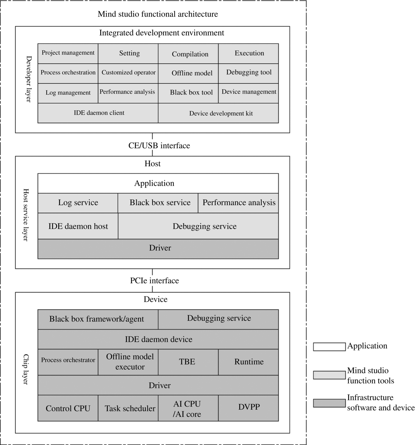
Mind Studio can be installed on a regular PC or workstation and supports running on Ubuntu Linux. Currently, it supports browser access. If you just do ordinary project management, writing code, compiling, model conversion, or running debugging in the simulation environment, you can do it on the machine with Mind Studio installed. If you need to run the development project on the real Ascend AI processor, you need to connect Mind Studio to the host and cooperate with the tool background service module on the host to complete the running, debugging, logging, and performance analysis of the developed project.
4.3.3: Tool functions
The tools provided in the Mind Studio toolchain are powerful. The following are the main features of the toolchain:
- (1) Project management tools: provide developers with functions such as project creation, project opening, project closure, project deletion, project export, project file directory addition, and property settings.
- (2) Compilation tools: provide development and compilation of operators, computation engines and applications to meet the development and compilation requirements of different scenarios of developers.
- (3) Operation tool: the operator and computation engine supporting development are run in the real processor environment, and the operation related information can be viewed in the interface uniformly.
- (4) Process orchestration tools: for business process developers, the process orchestration tool provides a drag-and-drop programming method based on business nodes. By dragging and dropping business nodes on Mind Studio and connecting them, the business can be arranged with “zero” coding. One-stop services such as compiling, running, and displaying results make the process development more intelligent. The whole process requires no programming. It is completely done by drag and drop and configuration. It is very simple. It allows developers to get started quickly, so that they can focus more on application performance improvement. And the tool itself does not bring any additional learning costs.
- (5) Customized operator tool: provides the industry’s first integrated development environment for operator programming development and debugging based on TBE, which makes the operator transplantation under different platforms more rapid, and adapts to the Ascend AI processor fast.
- (6) Offline model tool: the trained third-party network model can be directly imported and converted into an offline model through the offline model tool, and the model interface can be automatically generated in one click, which is convenient for developers to program based on the model interface, and also provides visualization of offline models.
- (7) Log management tool: Mind Studio provides the system-wide log collection and log analysis solution for the Ascend AI processor to improve the efficiency of identifying runtime algorithm problems. The unified system-wide log format provides cross-platform log visualization analysis capabilities and runtime diagnostic capabilities in a web-based format, improving the ease of use of the log analysis system.
- (8) Performance analysis tools: Mind Studio provides two-node, multimodule heterogeneous systems for efficient and easy-to-use, flexible, and scalable system performance analysis based on graphical interface and command-line user interface presentation. It also enables the synchronous analysis of performance and power consumption for the AI processor device, which meets the needs of algorithm optimization for system performance analysis.
- (9) Black box tool: the device saves the necessary key information of the system before the software reset and hardware reset and provides the interface visual viewing mode. Referred to as the black box, it is mainly used for the positioning of subsequent problems.
- (10) Device Management: Mind Studio provides device management tools to implement management functions for the developer board connected to the host.
- (11) Comparison tool: it can be used to compare the result of the customized operator by the TBE with the result of the Caffe standard operator, so as to confirm the cause of the neural network operation error. Mind Studio provides three comparison methods: Lower Bound, Vector, and User-define. The Lower Bound alignment is a TBE customized operator alignment. The Vector comparison contains an operator comparison of cosine similarity, maximum absolute error, cumulative relative error, and Euclidean relative distance. The user-define comparison refers to user-defined operator comparison.
- (12) Device Development Kit: provides developers with a related algorithm development kit based on the Ascend AI processor, designed to help developers develop fast and efficient artificial intelligence algorithms. Developers can install device development kits on Mind Studio, use Mind Studio development tools for rapid algorithm development, or use separate device development kits for algorithm development. The device development kit includes header files and library files, compiler toolchains, debugging and tuning tools, and other tools that are dependent on the development of the AI processor algorithm.