Chapter 2. Transport Independence
The primary focus of WANs is to provide the ability to exchange network traffic across geographic distances. In addition, scalability and cost are important factors for the design of a WAN. The provisioning and operation of a WAN can be a complex task for any network engineer because of the variety and behaviors of technologies available.
WAN Transport Technologies
Every technology has different costs and features (technical and ability to scale) that impact the overall design strategy for a WAN. The following sections provide an overview of WAN technologies as they were developed.
Dial-Up
Computers and routers connect with each other with analog modems that use the telephone companies’ public switched telephone network (PSTN). Using the existing PSTN infrastructure provides flexibility because connectivity can be established dynamically to any phone number. Telephone lines are required to support only voice, which needs 9600 bps of bandwidth. The speed that the first modem supported, 300 bps, has increased over time to up to 56,000 bps (56 kbps) where audio quality is ideal. Occasionally line quality can cause the modem session to disconnect, resulting in network routing convergence or packet loss while the call is reestablished. Dial-up access is a low-cost, flexible solution when temporary low-bandwidth connectivity is required.
Running routing protocols over a dial-up line can consume additional bandwidth and can cause additional convergence in the routing domain when the dial-up session disconnects. Typically static routes are used with dial-up connectivity.
Leased Circuits
Overcoming the speed barrier of dial-up connectivity requires the use of dedicated network links between the two sites. The cost to secure land rights, purchase cables and devices, and install the cables and acquire the hardware presents a financial barrier to most companies.
Telephone companies use the existing infrastructure and sell access between devices as dedicated leased lines. Leased lines provide high-bandwidth secure connections but lack the flexibility of dial-up. Regardless of link utilization, leased lines provide guaranteed bandwidth because the circuits are dedicated between sites in the SP environment.
Most SPs now install fiber-optic cables between locations; each cable contains multiple strands that support multiple connections. Only a portion of the cable strands is consumed, which means that additional capacity can be consumed internally or leased to other companies. Unused fiber-optic cables are called dark fiber circuits. Some companies specialize in locating and reselling dark fiber circuits. Customers are provided with a transport medium but are responsible for installing devices at each end for any routing or switching capabilities. Dark fiber is not really a service but more of an asset.
Organizations can take advantage of the full capability of fiber-optic cable (commonly 10 Gbps) by using dense wavelength-division multiplexing (DWDM) devices. These allow a 10 Gb interface to be assigned a specific optical wavelength, and because some fiber-optic cable supports multiple optical wavelengths, a single strand of cable supports multiple 10 Gb links. Bandwidth is guaranteed because only two devices can communicate on the same wavelength, and no wavelength conflicts with other wavelengths.
Virtual Circuits
Early connectivity for PSTN and leased lines allowed only point-to-point communication between two devices on the circuit. This complicated capacity planning from a telephone provider’s perspective and kept operating costs high. As the demand increased for circuits to carry data traffic in lieu of voice traffic, the need for a more efficient infrastructure increased.
Technologies like X25, Frame Relay, and ATM introduced the concept of sharing a line through the use of virtual circuits. Virtual circuits provide a tunnel for traffic to follow a specific path in an SP’s network. They allow multiple conversations to exist on physical links, reducing the SP’s operational costs and allowing communication with multiple devices using the same physical interface.
Virtual circuits provide the following advantages:
![]() Communication is allowed with more than two devices at the same time using the same interface.
Communication is allowed with more than two devices at the same time using the same interface.
![]() Interfaces can operate with different bandwidth settings between devices.
Interfaces can operate with different bandwidth settings between devices.
Note
Virtual circuits introduced the capability for point-to-multipoint, full-mesh, and partial-mesh Layer 2 networks that use the same Layer 3 network address. Point-to-multipoint and partial-mesh topologies deviate from standard broadcast and point-to-point transports and may require special configuration of routing protocols to work properly.
Peer-to-Peer Networks
With improvements in the Ethernet protocol, Ethernet links can support speeds of from 1 Mbps to 100 Gbps, exceeding other serial technologies such as T1 and SONET. For example, OC-768 serial circuits can transport only up to 38.5 Gbps. In addition, Ethernet is more cost-effective than serial technologies when the cost is compared on a per-bit basis.
The amount of bandwidth required at a remote site can vary depending upon the number of users and data services required at each site. Some remote sites may be able to support Ethernet connectivity, but other sites can connect only via serial links because of circuit length requirements. If two sites connect via two different transport media (such as Ethernet and serial) and must be able to communicate with each other, the SP typically provides the connectivity indirectly by routing (Layer 3) between the two sites.
Figure 2-1 illustrates an SP providing connectivity between Site 1 and Site 2 using different network media. There are CE routers located at the edge of the customer network and on the customer’s site. The CE routers connect to PE routers that are located at the SP’s site. The PE routers connect to provider (P) routers or other PE routers.

CE1 connects to PE1 via an Ethernet link (172.16.11.0/24), and CE3 connects to PE3 via a serial link (172.16.33.0/24). CE1 exchanges routes with PE1 via a dynamic routing protocol which is then advertised to P2 and then on to PE3. CE2’s routes are exchanged in an identical fashion toward CE1. In this model, the SP network provides network connectivity to both locations for both customers.
A peer-to-peer network distributes all aspects of the network among all its peers. A problem with peer-to-peer networks is that the SP participates in the network. Any existing networks in the SP’s network cannot be used in the customer’s network, and all IP address spaces are shared with everyone attached to it, including other customers.
In Figure 2-1, the peer-to-peer network is shared between two customers (Customer A and Customer B). Customer A cannot use the 172.16.2.0/24 network or the 172.16.4.0/24 network because Customer B is using them. This limitation can cause issues when two different companies use private IP addressing ranges (RFC 1918) and want to use the same network segment.
Note
The Internet is the world’s largest peer-to-peer network.
Broadband Networks
Home consumers have requested more and more bandwidth at an economical scale. Because of the large geographic area that required service, telephone, and cable companies needed a technology that could reuse portions of their existing infrastructure while providing more bandwidth to consumers. Multiplexing (combining) multiple frequencies on the same link enabled them to provide a higher amount of bandwidth to consumers. These types of networks are referred to as broadband networks because they combine multiple frequencies (bands) to provide bandwidth.
Broadband networks exist in two formats:
![]() Cable modem: Connectivity is provided through the existing coaxial infrastructure used by cable television providers. Initial cable modem speeds were 1 to 2 Mbps but currently provide 100+ Mbps. Because the coaxial infrastructure is shared among several locations, the bandwidth is shared and can fluctuate based on a neighbor’s bandwidth usage. Although bandwidth may peak to what is stated in the SLA, setting the bandwidth to the average is recommended.
Cable modem: Connectivity is provided through the existing coaxial infrastructure used by cable television providers. Initial cable modem speeds were 1 to 2 Mbps but currently provide 100+ Mbps. Because the coaxial infrastructure is shared among several locations, the bandwidth is shared and can fluctuate based on a neighbor’s bandwidth usage. Although bandwidth may peak to what is stated in the SLA, setting the bandwidth to the average is recommended.
![]() DSL: There are different variants of DSL, but in essence it uses the existing copper wires in the PSTN network that provide telephone service to a house. DSL uses higher frequencies that humans cannot hear to transmit data. It does not use a shared infrastructure but is generally limited to a small distance (about 2 to 5 km) from the telephone company’s head-end device. The farther away from the head-end device, the lower the available bandwidth. DSL can reach speeds in excess of 40 Mbps.
DSL: There are different variants of DSL, but in essence it uses the existing copper wires in the PSTN network that provide telephone service to a house. DSL uses higher frequencies that humans cannot hear to transmit data. It does not use a shared infrastructure but is generally limited to a small distance (about 2 to 5 km) from the telephone company’s head-end device. The farther away from the head-end device, the lower the available bandwidth. DSL can reach speeds in excess of 40 Mbps.
Broadband has since expanded in scale and is no longer considered a home consumer technology. Many telephone and cable companies also provide broadband services to businesses.
Cellular Wireless Networks
With the invention of the smartphone, cellular wireless providers allowed phones to send and transmit data in addition to placing voice calls. Cellular wireless networks provide the following benefits:
![]() Reachability: Not all businesses operate in places where an SP has circuits. In some remote locations (such as mountains or islands) cables for connectivity may not exist. The coverage of cellular wireless networks enables businesses to take the network into geographic locations that were never available via wired connections.
Reachability: Not all businesses operate in places where an SP has circuits. In some remote locations (such as mountains or islands) cables for connectivity may not exist. The coverage of cellular wireless networks enables businesses to take the network into geographic locations that were never available via wired connections.
![]() Backup connectivity: The speed of cellular networks offers businesses the ability to run their operations over what was typically used as an out-of-band management link. This means that cellular wireless networks can provide a second connection where multiple SPs are not available. This includes voice and video support over cellular in the event of a primary network outage.
Backup connectivity: The speed of cellular networks offers businesses the ability to run their operations over what was typically used as an out-of-band management link. This means that cellular wireless networks can provide a second connection where multiple SPs are not available. This includes voice and video support over cellular in the event of a primary network outage.
![]() Timeliness: Terrestrial circuits can typically take up to 90 days to deploy at new locations. The quick activation of cellular allows businesses to bring locations and services online in days or even hours instead of weeks or months.
Timeliness: Terrestrial circuits can typically take up to 90 days to deploy at new locations. The quick activation of cellular allows businesses to bring locations and services online in days or even hours instead of weeks or months.
![]() Ability to host networks that change in location: Some mobile vendors (such as food trucks) need network connectivity to verify credit card transactions. Another growing sector is the use of cellular wireless networks to track a patient’s vital signs while the patient is at home, reducing the patient’s need to visit a healthcare facility, or making care available to patients who are unable to travel.
Ability to host networks that change in location: Some mobile vendors (such as food trucks) need network connectivity to verify credit card transactions. Another growing sector is the use of cellular wireless networks to track a patient’s vital signs while the patient is at home, reducing the patient’s need to visit a healthcare facility, or making care available to patients who are unable to travel.
![]() Ability to host networks in motion: Some businesses require the ability to provide network connectivity to devices in motion. For example, passenger trains may provide WiFi service to their passengers, track critical on-board sensors, or combine GPS sensors to track the vehicle location.
Ability to host networks in motion: Some businesses require the ability to provide network connectivity to devices in motion. For example, passenger trains may provide WiFi service to their passengers, track critical on-board sensors, or combine GPS sensors to track the vehicle location.
Virtual Private Networks (VPNs)
Ensuring that an SP can provide connectivity to two different locations can be a problem. An SP may have only regional connectivity and not global capabilities. Providing connectivity to customers with a global footprint is not an easy task for many SPs, particularly those with only a regional presence. In the event that a global SP cannot be found, regional SPs must be interconnected. This scenario increases operational complexity when connectivity must be provided between sites in different countries or continents. Scenarios like this may prevent a peer-to-peer solution; however, Internet connectivity is common throughout the world and easy to obtain almost anywhere.
A VPN provides connectivity to private networks over a public network, such as the Internet. A VPN operates by tunneling, encrypting the payload, or both. With VPN tunneling, packets destined to travel between private networks are encapsulated and assigned new packet headers that allow the packets to traverse the public network. A VPN tunnel is classified as an overlay network because the VPN network is built on top of an existing transport network, also known as an underlay network. After authenticating with the remote VPN endpoint, the VPN tunnel is established for packets to traverse to the private network. A VPN can leverage public network transport such as the Internet to provide global connectivity using only one transport.
Note
VPNs are not restricted to use on the Internet. Many organizations use VPNs across corporate networks to ensure that sensitive data is not compromised in transit between geographic locations.
Within VPN tunnels, the new packet headers provide a method of forwarding a packet across the public network without exposing the private network’s original packet headers. This allows the packet to be forwarded between the two endpoints without requiring any routers to extract information from the payload (original packet headers and data). After the packet reaches the remote endpoint, the VPN tunnel headers are decapsulated (removed). The endpoint checks the original headers and then forwards the packet through the appropriate interface to the private network.
There are multiple VPN protocols with various benefits and design considerations for encapsulating, encrypting, and transferring data across public networks. Internet Protocol Security (IPsec), Secure Sockets Layer (SSL), Datagram Transport Layer Security (DTLS), and Point-to-Point Tunneling Protocol (PPTP) are some of the most common protocols used today for VPNs. The following sections explain the most common VPN types.
Remote Access VPN
A company’s employees or partners can install VPN software on a client device (workstation, tablet, or phone) that can establish a VPN tunnel to the VPN server. The client must know the VPN server’s public IP address, but the VPN server does not need to know the client’s public IP address in advance. The VPN server assigns a private IP address to the client so that devices in the remote private network know where to send return network traffic.
Typically the VPN server defines any access or security policies on the client. The VPN server can require that all traffic from the client be sent across the VPN tunnel, known as full tunnel, or specify that traffic to only specific destination networks route across the VPN tunnel, known as split tunneling.
Site-to-Site VPN Tunnels
Remote access VPN solutions do not scale well for locations with multiple VPN clients like branch offices. A better scalable solution uses a dedicated VPN client (router, firewall, or security appliance) to provide connectivity to the remote VPN server via a site-to-site VPN tunnel.
Each VPN endpoint must know the public IP address of the other. In addition, the endpoints must identify the interesting traffic (source and destination networks) that will use the VPN tunnel. If there is a mismatch of interesting traffic, either the packets are not encapsulated properly or the packets are not decapsulated and are dropped.
When the first VPN endpoint receives interesting traffic, the VPN tunnel is established. Private network packets are encapsulated, routed across the public network toward the remote endpoint, and decapsulated. Depending on the endpoint configuration, the VPN tunnel remains up indefinitely, or an idle timer can be configured. The idle timer is reset if packets come across the tunnel. If the timer reaches zero, the VPN tunnel is torn down.
Note
Typical IPsec tunnels (those that are not generic routing encapsulated [GRE]) do not assign a network (subnet) to the tunnel, which prevents Interior Gateway Protocol (IGP) routing protocols from operating on the tunnel. Advertising the remote routes to downstream devices requires the use of reverse-route injection or other techniques.
Hub-and-Spoke Topology
Organizations with more than two locations typically establish site-to-site VPNs between the headquarters and the branch sites using a hub-and-spoke network topology. Network traffic from one branch to a different branch must travel from the branch (spoke) to the headquarters (hub) location and then back to the remote branch.
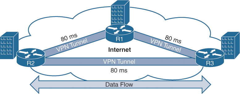
Figure 2-2 illustrates a typical hub-and-spoke topology between R1, R2, and R3.

R1 is the hub, and R2 and R3 are spokes. Network latency from either spoke to the hub is 110 ms, which is generally an acceptable latency for most applications. The end-to-end latency between spokes (R2 to R3) is 220 ms, which may be acceptable for most applications but can cause problems for others. For example, VoIP recommends a maximum delay of 150 ms. Exceeding the recommended delay can affect call audio quality for users at R2 talking with users at R3.
Allocating proper bandwidth for the hub site is critical. The hub site is the typical destination for most network traffic, but traffic between other spokes must transit the hub circuit twice, one time inbound and another leaving the hub to the other branch site. Although oversubscription of spoke bandwidth is common, bandwidth oversubscription at the hub site should not be common.
Note
Adding a new site to a hub-and-spoke topology requires additional configuration (endpoint IP addressing, defining interesting traffic, cryptography, route table manipulation) on the new spoke router and on the hub router. The formula n*2 provides the number of VPN interfaces (tunnel endpoints) that must be configured for the routing domain, where n reflects the number of sites. In Figure 2-2 there are two sites, which require four VPN tunnel interfaces (two on R1, one on R2, and one on R3).
Full-Mesh Topology
To address some of the deficiencies of the hub-and-spoke model, VPN tunnels can be established between R2 and R3, thereby forming a full-mesh topology. Doing so can reduce the end-to-end latency between all sites, assuming that the latency in the transport network between R2 and R3 is less. In this scenario the latency is 110 ms, which provides sufficient voice call quality and improves the responsiveness of other applications. In addition, network traffic between the sites does not consume bandwidth from R1 unnecessarily.
Figure 2-3 shows all three sites with direct site-to-site connectivity. This illustrates a full-mesh topology because all sites are connected to all other sites regardless of size.
Full-mesh topologies using site-to-site VPN tunnels can introduce a variety of issues as the number of sites increases. Those issues are
![]() Manageability of VPN endpoints: When a new site needs connectivity, the VPN tunnel interface needs to be configured on the new router and the remote router. The formula n(n−1) provides the number of VPN tunnel interfaces that must be configured, where n reflects the number of sites. In Figure 2-3 there are three sites, but the topology requires the creation of six VPN tunnel endpoints. The problem is further exacerbated when 10 sites are required because 90 VPN tunnel interfaces must be managed.
Manageability of VPN endpoints: When a new site needs connectivity, the VPN tunnel interface needs to be configured on the new router and the remote router. The formula n(n−1) provides the number of VPN tunnel interfaces that must be configured, where n reflects the number of sites. In Figure 2-3 there are three sites, but the topology requires the creation of six VPN tunnel endpoints. The problem is further exacerbated when 10 sites are required because 90 VPN tunnel interfaces must be managed.
![]() Consumption of router CPU and memory: Maintaining a high number of active VPN tunnels consumes more CPU and memory resources. All routers need to be sized accordingly to accommodate any load generated for maintaining the VPN tunnels.
Consumption of router CPU and memory: Maintaining a high number of active VPN tunnels consumes more CPU and memory resources. All routers need to be sized accordingly to accommodate any load generated for maintaining the VPN tunnels.
Most VPN designs for large organizations typically place a hub in a major geographic region. The hub is connected via full-mesh, and then the interregion traffic is contained via a hub-and-spoke model.
Multiprotocol Label Switching (MPLS) VPNs
Service providers use Multiprotocol Label Switching (MPLS) to provide a scalable peer-to-peer architecture that allows packets to transit the SP network from PE router to PE router without the need to look into the packets’ contents. The MPLS VPNs use at least two MPLS labels, one for the forwarding of packets between PE routers and the other to identify which customer’s network the packet belongs to. Because a customer network is specified in the second MPLS label, IP addressing is not shared between customers. This allows the SP to offer VPN connectivity for multiple customers that often use the same private IP address space (RFC 1918).
An MPLS network forwards traffic based upon the outermost MPLS label of a packet. The MPLS labels are placed before the IP headers (source IP and destination IP), so none of the transit routers require examination of the packet’s IP header or payload. As packets cross the core of the network, the source and destination IP addresses are never checked as long as the forwarding label exists in the packet. Only the PE routers need to know how to send the packets toward the CE router. An MPLS VPN is considered an overlay network because network traffic is forwarded on the SP’s underlay network using MPLS labels.
All MPLS VPNs are categorized by two technologies on the PE router: Layer 2 and Layer 3 VPN.
Layer 2 VPN (L2VPN)
PE routers provide connectivity to customer routers by creating a virtual circuit between two nodes. Packets are received on an interface, labeled with a circuit ID, then labeled for the remote PE.
Virtual Private LAN Service (VPLS) is an evolution of L2VPN that provides multisite access to the same bridge domain. A VPLS includes logic to maintain MAC address table mappings to a specific PE router and provides the capability of LAN switching to devices spread across large geographic areas.
An L2VPN can be set up with topologies of point-to-point, point-to-multipoint, or full-mesh. This technology allows for all packets to be exchanged between PE routers.
Layer 3 VPN (L3VPN)
A PE router uses a virtual context known as Virtual Route Forwarding (VRF) for each customer. In order to provide segmentation and maintain exclusive communications between customer sites, every VRF context provides a method for routers to maintain a separate routing and forwarding table for each customer.
The PE routers must contain all the routes for a particular customer (VRF), whereas the CE routers require only a default route to the PE router. The route table on the PE routers can be programmed via a static route at the local PE router or is advertised from the CE router. A PE router exchanges the VRF’s routes with other PE routers using Multiprotocol Border Gateway Protocol (MBGP) using a special address family just for MPLS L3VPN networks. There are VPN labels associated to each of the VRF’s routes to identify which VRF the routes belong to.
A CE router can use only a static default route toward the closest PE router, and the PE routers are responsible for maintaining and exchanging the complete routing table for that VRF using MBGP. But the CE router can use a routing protocol to dynamically advertise networks to the PE routers. This allows the PE routers to have a complete routing table that is dynamically learned versus statically configured. BGP is commonly used to exchange routes between CE and PE routers because of its scalability and capability for route policy manipulation.
MPLS is enabled in the SP network to forward traffic between PE routers. A packet is forwarded based upon the outermost label of the packet that references the destination PE router. Only the edge PE routers need to examine other portions of the packet (internal MPLS labels, packet headers, and payload) as they send traffic to the CE router.
Using MPLS VPNs provides reliable bandwidth because the SP owns the entire infrastructure. Deploying a new site requires connecting a new circuit between the CE router and the PE router. Minor configuration is needed on the PE router with the new circuit, and then that remote site has full connectivity to all other sites in the MPLS VPN.
The primary difference between L2VPNs and L3VPNs is how the CE-PE relationship is handled. L2VPNs are concerned only from the Layer 2 perspective, whereas L3VPNs participate in the routing table of the customer networks. Both models provide security to the customer networks through circuit/network segmentation, and the SP network is invisible to the customer. Each model has its advantages and disadvantages.
MPLS VPNs and Encryption
A common misunderstanding of network and information security engineers is whether the payload is encrypted for MPLS VPNs. MPLS VPNs do not typically encrypt packets that travel across them. MPLS labels are used to forward the packets and associate them to a VRF (for L3VPN) or to a circuit (for L2VPN). It is possible for data to leak between customers if there is a misconfiguration within the SP network.
Some organizations that are subject to stringent privacy regulations (such as healthcare, government, and financial) often require all traffic to be encrypted across all WAN links; other organizations encrypt traffic only where they feel vital data can be compromised. In instances like these, a second technology to encrypt and decrypt the traffic must be deployed.
Link Oversubscription on Multipoint Topologies
Routers are aware of the available bandwidth only for the circuit to which they are connected. They are not aware of the bandwidth on the remote link. Service providers size a circuit based on the total capacity to send and receive traffic. In point-to-point technologies, ensuring that a link is not oversubscribed is straightforward, because the SP keeps the bandwidth the same at both connection points. Network traffic is shaped outbound on both routers to match the rate identified by the SP.
Figure 2-4 illustrates this concept. The link connecting R1 and R2 allows 10 Mbps of traffic in each direction. R1 receives 20 Mbps of traffic locally, but R1 shapes the traffic down to a 10 Mbps traffic stream when sending on to R2. R2 receives a 15 Mbps traffic stream locally, but R2 shapes the traffic to a 10 Mbps traffic stream before sending it on to R1. If the QoS class buffers become full, packets should be dropped before traffic is sent across the link.

The same logic may not apply to multipoint topologies because sites may have different bandwidth connectivity. It is possible for one router to send more traffic than the remote network can accept. When this happens, bandwidth is wasted on the transmitting router’s link because those packets will ultimately be dropped. In addition, it is possible to prevent a recipient’s router from receiving traffic from a different site.
Figure 2-5 illustrates the concept. Company ABC is using an MPLS VPN for connectivity between its headquarters (HQ) and branch sites. A majority of the network traffic is from the Los Angeles headquarters site to the Miami branch site. R1’s circuit bandwidth has been sized to allow simultaneous communication with R2 and R3.

Unfortunately this causes problems instead. The problem is that R1 is not aware of R3’s bandwidth and transmits up to a rate of 10 Mbps, whereas R3 can receive only 5 Mbps of traffic. The SP drops traffic that exceeds 5 Mbps as it is being sent to R3. In addition to wasting some of R1’s bandwidth, R2 cannot communicate with R3 because R3’s link is oversubscribed.
Dynamic Multipoint VPN (DMVPN)
Dynamic Multipoint VPN (DMVPN) is a Cisco overlay routing solution that addresses the deficiencies of site-to-site VPN tunnels. Remote locations (spokes) establish a static tunnel to a centralized location (hub) but are also capable of establishing connectivity to other remote locations with a dynamic spoke-to-spoke tunnel.
The dynamic spoke-to-spoke behavior allows full-mesh connectivity without the additional management of providing full-mesh connectivity. The spoke-to-spoke tunnels are removed after a certain period of inactivity, freeing up router memory and CPU. Because the site-to-site tunnels are dynamic, the spoke routers do not require as much memory or CPU as the hub routers.
Figure 2-6 illustrates a DMVPN tunnel where R1 is the hub and R2, R3, and R4 are spoke routers. R2 and R4 establish a dynamic spoke-to-spoke tunnel for direct communication, and eventually that dynamic tunnel is torn down after it is no longer needed.

DMVPN uses the following technologies:
![]() Multipoint generic routing encapsulated (mGRE) tunnels: mGRE is an overlay tunneling protocol that transports multiple protocols such as IPv4, IPv6, IPX (Internetwork Packet Exchange), and so on. Unlike IPsec VPN tunnels, GRE tunnels are assigned an actual interface and require addressing on the tunnel interface. Unlike traditional GRE tunnels which are point-to-point, mGRE supports more than two devices on the overlay network.
Multipoint generic routing encapsulated (mGRE) tunnels: mGRE is an overlay tunneling protocol that transports multiple protocols such as IPv4, IPv6, IPX (Internetwork Packet Exchange), and so on. Unlike IPsec VPN tunnels, GRE tunnels are assigned an actual interface and require addressing on the tunnel interface. Unlike traditional GRE tunnels which are point-to-point, mGRE supports more than two devices on the overlay network.
![]() Next Hop Resolution Protocol (NHRP): Because of the dynamic nature of DMVPN, the DMVPN spoke routers need a method to associate the tunnel endpoint IP address with the transport IP address for other DMVPN routers. NHRP provides IP resolution to next-hop clients (NHCs) by registering and querying a next-hop server (NHS). Originally used for mapping IP addresses on .X25 networks, it is now used for resolving the tunnel endpoint addresses to the logical IP addresses of DMVPN network cloud. The protocol was defined in RFC 2332.
Next Hop Resolution Protocol (NHRP): Because of the dynamic nature of DMVPN, the DMVPN spoke routers need a method to associate the tunnel endpoint IP address with the transport IP address for other DMVPN routers. NHRP provides IP resolution to next-hop clients (NHCs) by registering and querying a next-hop server (NHS). Originally used for mapping IP addresses on .X25 networks, it is now used for resolving the tunnel endpoint addresses to the logical IP addresses of DMVPN network cloud. The protocol was defined in RFC 2332.
![]() IPsec tunnel protection (optional): IPsec uses cryptography to authenticate and encrypt IP network traffic across networks. It supports Internet Key Exchange (IKE) v1 and v2, and the Suite-B next-generation encryption technologies.
IPsec tunnel protection (optional): IPsec uses cryptography to authenticate and encrypt IP network traffic across networks. It supports Internet Key Exchange (IKE) v1 and v2, and the Suite-B next-generation encryption technologies.
DMVPN provides the following benefits over traditional site-to-site IPsec VPN:
![]() Zero-touch hub: Adding more spoke routers does not require any additional configuration on the hub router. This simplifies the ongoing maintenance of the hub routers. Resolution of spoke endpoint IP addressing is accomplished with NHRP.
Zero-touch hub: Adding more spoke routers does not require any additional configuration on the hub router. This simplifies the ongoing maintenance of the hub routers. Resolution of spoke endpoint IP addressing is accomplished with NHRP.
![]() Spoke-to-spoke communication: Phases 2 and 3 of NHRP support dynamic spoke-to-spoke network connectivity. All the DMVPN routers obtain the benefits of a full-mesh topology but conserve router resources by creating tunnels between VPN endpoints only as needed. Spoke-to-spoke communication reduces latency and jitter, while avoiding consumption of bandwidth at hub locations.
Spoke-to-spoke communication: Phases 2 and 3 of NHRP support dynamic spoke-to-spoke network connectivity. All the DMVPN routers obtain the benefits of a full-mesh topology but conserve router resources by creating tunnels between VPN endpoints only as needed. Spoke-to-spoke communication reduces latency and jitter, while avoiding consumption of bandwidth at hub locations.
![]() Tunnel IP addressing: DMVPN uses GRE tunnels that use IP addressing in the overlay network. IPv4 or IPv6 addresses can be used in the overlay or to provide connectivity in the underlay. Routing protocols can run on top of the DMVPN tunnel, thereby allowing dynamic network updates versus manually updating the routing tables when using IPsec VPN tunnels.
Tunnel IP addressing: DMVPN uses GRE tunnels that use IP addressing in the overlay network. IPv4 or IPv6 addresses can be used in the overlay or to provide connectivity in the underlay. Routing protocols can run on top of the DMVPN tunnel, thereby allowing dynamic network updates versus manually updating the routing tables when using IPsec VPN tunnels.
Note
Some networks use DMVPN as a method of providing IPv6 connectivity across an IPv4 network.
![]() Encryption is optional: The benefits of overlay routing can be obtained with MPLS L3VPN networks without unnecessary consumption of router resources for encryption. DMVPN tunnels operating on insecure networks (such as the Internet) typically encrypt the payload with IPsec technologies.
Encryption is optional: The benefits of overlay routing can be obtained with MPLS L3VPN networks without unnecessary consumption of router resources for encryption. DMVPN tunnels operating on insecure networks (such as the Internet) typically encrypt the payload with IPsec technologies.
![]() Multicast support: Native IPsec VPN tunnels do not support multicast traffic, which complicates the ability to transmit multicast traffic from branch sites to headquarters sites. DMVPN provides multicast support between hub-and-spoke devices for hub-to-spoke traffic flows.
Multicast support: Native IPsec VPN tunnels do not support multicast traffic, which complicates the ability to transmit multicast traffic from branch sites to headquarters sites. DMVPN provides multicast support between hub-and-spoke devices for hub-to-spoke traffic flows.
![]() Per-tunnel QoS: DMVPN supports the ability of the DMVPN hub to set different QoS and bandwidth policies for each tunnel to a spoke router based on the site’s connectivity model.
Per-tunnel QoS: DMVPN supports the ability of the DMVPN hub to set different QoS and bandwidth policies for each tunnel to a spoke router based on the site’s connectivity model.
Benefits of Transport Independence
All the traditional transports (dial-up, leased circuits, MPLS, and IPsec VPNs) have advantages and disadvantages. One transport may prefer one routing protocol whereas a different transport may prefer a different routing protocol. Some transports are not always available or cost-effective at all locations. Intermixing multiple transports into a native WAN architecture can result in a complex WAN environment.
Ensuring that the network is always available for business purposes requires that there not be any SPOFs. Network architects plan for backup circuits that are active only when the primary circuit fails, or dual circuits that can be used at the same time. Network architects must also decide on the number of routers at each site, whether a router is dedicated to each circuit, or if both circuits should connect to the same router.
Using a single router with a single transport provides “three nines” (99.9%) of availability, which correlates to about four to nine hours of downtime a year. Using a single router with two transports provides “four nines” (99.995%) of availability, correlating to 26 minutes of downtime a year. Using two routers, each with its own transport, provides “five nines” (99.999%) of availability, which correlates to five minutes of downtime a year.
Figure 2-7 depicts a typical scenario for Company ABC, which uses two different providers and transports because it cannot locate two SPs that provide the same service at both the branch and headquarters. ABC uses MPLS L3VPN from one SP and creates an IPsec tunnel across the Internet for a backup circuit. R1 and R2 form an external BGP (EBGP) session to the MPLS L3VPN provider, and the routers use static routes and reverse-route injection to send traffic across the IPsec tunnel.

In scenarios like the one shown in Figure 2-7, one transport acts as a primary and the other as a backup, and there are multiple routing protocols on the WAN routers that require advanced configuration to ensure that the correct path is taken. The complexity increases when routes are exchanged between IGP (Enhanced IGRP [EIGRP], Open Shortest Path First [OSPF], and so forth) at each site and the WAN routing protocols, which could lead to suboptimal routing or routing loops.
A well-designed network architecture should take into account the operational support staff and reduce complexity where possible. It should account for junior-level engineers working in the network operations center (NOC) performing day-to-day management of the network. Redistribution between protocols should be kept to a minimum to prevent confusion and routing loops. The design should be modular to support future growth and allow for a simple migration between SPs to address business needs.
DMVPN provides transport independence through the use of full-mesh overlay routing. This technology allows organizations to use multiple WAN transports, because the transport type is associated to the underlay network and is irrelevant to the overlay network. The overlay network is consistent and normalized to the DMVPN tunnel.
Transport independence allows operational consistency for WAN architectures by providing the following:
![]() Single routing domain: Traditional routing protocols were designed to solve the endpoint reachability problem in a hop-by-hop destination-only forwarding environment of unknown topology. The routing protocols choose only the best path based on statically assigned cost. Because DMVPN presents a flat topology, it provides a consistent topology that allows ECMP load balancing across DMVPN tunnels.
Single routing domain: Traditional routing protocols were designed to solve the endpoint reachability problem in a hop-by-hop destination-only forwarding environment of unknown topology. The routing protocols choose only the best path based on statically assigned cost. Because DMVPN presents a flat topology, it provides a consistent topology that allows ECMP load balancing across DMVPN tunnels.
![]() Consistent troubleshooting: The same process can be used for troubleshooting connectivity for the DMVPN tunnel and the underlay network. Even though the underlay transport changes, it relies on basic IP connectivity between tunnel endpoints.
Consistent troubleshooting: The same process can be used for troubleshooting connectivity for the DMVPN tunnel and the underlay network. Even though the underlay transport changes, it relies on basic IP connectivity between tunnel endpoints.
![]() Consistent topology: There is a consistent topology and methodology for deploying other services such as performance routing.
Consistent topology: There is a consistent topology and methodology for deploying other services such as performance routing.
Figure 2-8 illustrates the same topology as before except that R1 and R2 use a DMVPN tunnel for each different transport (path). Company ABC can use the same routing protocol across both paths while maintaining a consistent topology. In addition, it can change one of the WAN transports at a later time without impacting the overall WAN design or operational support model.

Note
An example use case for transport independence is when a company deploys a new branch. Most SPs have a 60- to 90-day lead time for new circuit installation. A company can immediately deploy a router using a cellular data plan and then switch to the ordered circuit at a later time with minimal changes to the configuration. The operational support model remains the same regardless of which WAN transport is used.
Managing Bandwidth Cost
Three common solutions for providing additional bandwidth are
![]() Increasing bandwidth to existing primary paths, which can be expensive
Increasing bandwidth to existing primary paths, which can be expensive
![]() Deploying additional network circuits, sometimes using low-cost residential circuits
Deploying additional network circuits, sometimes using low-cost residential circuits
![]() Deploying application optimization technologies such as Cisco WAAS
Deploying application optimization technologies such as Cisco WAAS
![]() Deploying intelligent load-balancing technologies such as PfR
Deploying intelligent load-balancing technologies such as PfR
Additional WAN bandwidth improves aggregate throughput but does not improve end-to-end delay or packet loss for critical applications. Furthermore, additional bandwidth can be expensive, especially in rural areas where faster connections may not be available. At the same time, the cost of Internet connectivity is generally decreasing while reliability is increasing, as shown in Figure 2-9. Enterprises are now qualifying the Internet transport as an alternative business-class WAN circuit.

Leveraging the Internet
Enterprises face a big bandwidth challenge as guaranteed access bandwidth becomes more costly; they need to determine how to create a secure, reliable, and optimized network. According to Nemertes Research (“Benchmark 2012–2013 Emerging WAN Trends: The Internet Arises,” July 1, 2013), nearly half (46%) of all businesses are migrating, or are planning to migrate, their WAN to the Internet for transport. The Internet has become a much more stable platform, and the price-to-performance gains are compelling.
Offloading network traffic to the Internet can help load-balance best-effort traffic (that is, lower-priority traffic) across both links to help deal with traffic from business VPN access. In addition, administrators can use local Internet access for a distributed Internet access model to offload employee traffic that goes directly to public cloud services (such as Google Apps, Salesforce.com, Office 365, and so on) from the private WAN altogether.
This approach uses the Internet connection not just as a backup but as a real component in dealing with WAN workloads. With the right network technologies to optimize the flows, administrators can reduce overall WAN transport bandwidth requirements and improve application performance.
Intelligent WAN Transport Models
Internet- and MPLS-based VPNs are the most common WAN transports. Taking into account each transport type and the need for redundancy, there are three typical WAN deployment models:
![]() Dual MPLS: The first transport is an MPLS VPN provided by one SP, and a second MPLS VPN provided by a second SP. Assuming that both providers use the same type of MPLS VPN (all MPLS L3VPN or all MPLS L2VPN), the same routing protocol can be used.
Dual MPLS: The first transport is an MPLS VPN provided by one SP, and a second MPLS VPN provided by a second SP. Assuming that both providers use the same type of MPLS VPN (all MPLS L3VPN or all MPLS L2VPN), the same routing protocol can be used.
![]() Dual hybrid: The first transport is an MPLS VPN provided by one SP, and Internet connectivity is a second transport. The Internet transport can be provided by the same or a different SP. Ideally the SPs would use different “last mile” circuits and routers to eliminate SPOFs. The Internet circuit is used to establish a VPN service to another site.
Dual hybrid: The first transport is an MPLS VPN provided by one SP, and Internet connectivity is a second transport. The Internet transport can be provided by the same or a different SP. Ideally the SPs would use different “last mile” circuits and routers to eliminate SPOFs. The Internet circuit is used to establish a VPN service to another site.
This model provides connectivity for a distributed Internet model for all or select Internet-based traffic. It is possible to allow Internet access only for IT-approved cloud applications.
![]() Dual Internet: The first transport is Internet connectivity provided by one SP, and Internet connectivity is provided by a different SP for resiliency purposes. This model provides connectivity for a distributed Internet model too and does not have to be restricted to only VPN tunnels.
Dual Internet: The first transport is Internet connectivity provided by one SP, and Internet connectivity is provided by a different SP for resiliency purposes. This model provides connectivity for a distributed Internet model too and does not have to be restricted to only VPN tunnels.
Note
It is important to understand the BGP best-path algorithm when using multiple Internet SPs that cannot completely provide connectivity to all your locations. Typically BGP AS_Path length determines the path a packet takes on the Internet. If you have to use multiple Internet SPs to provide connectivity for one transport, it may be possible for the paths to take the same route through a transit Internet SP.
In all three models, deploying a DMVPN tunnel for each transport provides transport independence and simplifies the routing domain, operational model, and troubleshooting.
Implementing transport independence on existing circuits provides flexibility and leverage during circuit renewals. Typically, using the Internet as a transport maintains a lower cost than using an MPLS VPN for a transport and may produce savings to your company.
Figure 2-10 illustrates three of the Cisco Intelligent WAN (IWAN) models. Notice the connectivity to the Internet and cloud-based applications for all three models. Internet connectivity is available only through the headquarters in dual MPLS, whereas the hybrid and dual Internet models can provide Internet and cloud connectivity directly at the branch.

Note
The IWAN architecture does not limit the WAN design to only two transports. It is possible to use three or more transports to provide a custom solution. For example, you could use two different SPs providing MPLS VPN transports and a third SP providing Internet connectivity for a transport. All three transports would use DMVPN to keep the routing and topology consistent.
Summary
This chapter provided the history and overview of various WAN transports that are available today. Every WAN transport technology has advantages and disadvantages. Some remote locations cannot be serviced by an existing SP or provide the same time of transport as other sites.
Properly designed network architecture takes into account the skill level of the network engineers who support and maintain the network. The architecture should be consistent and scalable to ensure consistency in the environment regardless of the technology. Using DMVPN on top of the WAN transports provides a consistent operational model and provides transport independence while
![]() Simplifying the WAN with easy multihoming to SPs with a consistent design over all transports
Simplifying the WAN with easy multihoming to SPs with a consistent design over all transports
![]() Providing scalable full-mesh connectivity among all DMVPN routers
Providing scalable full-mesh connectivity among all DMVPN routers
![]() Providing a platform that supports proven robust security and cryptography
Providing a platform that supports proven robust security and cryptography
![]() Providing zero-touch configuration on DMVPN hub routers as branch sites are added
Providing zero-touch configuration on DMVPN hub routers as branch sites are added
DMVPN is explained in greater detail in the following chapters.