Chapter 12. Cisco Wide Area Application Services (WAAS)
This chapter covers the following topics:
![]() Interception techniques and protocols
Interception techniques and protocols
![]() WAAS design and performance metrics
WAAS design and performance metrics
Cisco WAAS is a software component that resides on hardware devices deployed at each network site. WAAS can run on a hypervisor, a router-integrated network module, or a dedicated appliance.
This chapter covers the WAAS architecture and interception techniques and looks at the positioning for each of the hardware platforms, as well as the performance and scalability metrics for each platform.
Note
“Application optimizers” and “application accelerators” are terms that are used interchangeably throughout this chapter.
Cisco WAAS Architecture
The Cisco WAAS architecture is based on the Cisco Linux OS. The Cisco Linux OS is hardened to ensure that rogue services are not installed, and secured to prevent third-party software installation and other changes. The Cisco Linux OS provides a CLI shell similar to Cisco IOS devices. This special CLI shell, along with the WAAS Central Manager, makes up the primary means of configuring, managing, and troubleshooting a WAAS device or system.
All relevant configuration, management, monitoring, and troubleshooting subsystems are made accessible directly through this CLI as opposed to exposing the actual Linux operating system.
The Cisco Linux platform hosts a variety of services for WAAS run-time operation such as disk encryption, Central Management Subsystem (CMS), interface manager, reporting facilities, network interception and bypass, and Application Traffic Policy (ATP) engine, as shown in Figure 12-1.

The following sections examine each of the Cisco WAAS architecture items. Cisco WAAS optimization components, including Data Redundancy Elimination (DRE), persistent LZ (PLZ) compression, transport flow optimization (TFO), and application accelerators, were discussed in Chapter 11, “Introduction to Application Optimization,” and are not discussed in this chapter.
Central Management Subsystem
CMS is a process that runs on each WAAS device, including accelerators and Central Managers. This process manages the configuration and monitoring components of a WAAS device and ensures that each WAAS device is synchronized with the Central Manager based on a scheduler known as the Local Central Manager (LCM) cycle. The LCM cycle is responsible for synchronizing the Central Manager CMS process with the remote WAAS devices. The CMS process exchanges configuration data, fetches health and status information, and gathers monitoring and reporting data. The CMS process is tied to a management interface known as the primary interface. The primary interface is configured on the WAAS device CLI prior to registration to the Central Manager. Any communication that occurs between WAAS devices for CMS purposes uses SSL for security.
Interface Manager
The Cisco WAAS device interface manager manages the physical and logical interfaces that are available on the WAAS device. Each WAAS device includes two integrated Gigabit Ethernet interfaces. Each WAAS appliance has expansion slots to support one or more additional feature cards, such as the inline module.
The interface manager provides management of logical interfaces. The first logical interface is the port channel interface, which can be used to aggregate (802.3ad) WAAS device interfaces together for the purposes of high availability and load balancing. The second logical interface is the standby interface. A standby interface has multiple physical interfaces associated to it, where one physical interface is active and a second interface is used as a backup in the event the active interface fails.
Note
Standby interfaces are used when WAAS device interfaces connect to separate switches, whereas port channel interfaces are used when the WAAS device interfaces connect to the same switch. Port channels can also be used between multiple switches that support virtual port channel (vPC) or virtual switching system (VSS).
Monitoring Facilities and Alarms
Cisco WAAS supports SNMP versions 1, 2c, and 3 and a variety of MIBs that provide complete health reporting of each individual WAAS device. Cisco WAAS provides support for NetFlow and the definition of up to four syslog servers, which can be used as alarm recipients when syslog messages are generated.
The WAAS Central Manager has an alarm dashboard. The Central Manager offers an API that is available for third-party visibility and monitoring systems. Transaction logs can be configured to be stored on each of the accelerator devices in the network for persistent retention of connection statistics, which may be useful for troubleshooting, debugging, or analytics purposes.
Network Interception and Bypass Manager
The Cisco WAAS device uses the network interception and bypass manager to establish relationships with intercepting devices where necessary and ensure low-latency bypass of traffic that the WAAS device is not intended to handle.
The Web Cache Communication Protocol (WCCP) version 2 (WCCPv2) is a protocol managed by the network interception and bypass manager to allow the WAAS device to successfully join a WCCPv2 service group with one or more adjacent routers, switches, or other WCCPv2-capable server devices. Other network interception options include policy-based routing (PBR) and physical inline interception. As flows are intercepted by the WAAS device and determined to be candidates for optimization, they are handed to the ATP engine to identify what level of optimization and acceleration should be applied based on the configured policies and classifier matches.
Application Traffic Policy Engine
The foundational optimization layer of the Cisco WAAS software is the ATP engine. The ATP engine is responsible for examining details of each incoming flow (after being handled by the interception and bypass mechanisms) in an attempt to identify the application or protocol associated with the flow. This association is done by comparing the packet headers from each flow against a set of classifiers that identify network traffic based upon one or more match conditions in the protocol fields. A classifier can be predefined, administratively configured, or dynamic.
WAAS policies are evaluated in priority order, and the first classifier and policy match determine the action taken against the flow and where the statistics for that flow are aggregated. Flows that do not have a match with an existing classifier are considered “other” traffic and are handled according to the policy defined for other traffic, which indicates that there are no classifier matches and that the default policy should be used.
Optimization class maps associate an application classification with a policy map that provides the action on a particular flow.
When a classifier match is found, the ATP engine examines the policy configuration for that classifier to determine how to optimize the flow. The ATP engine also notes the application group to which the classifier belongs to route statistics gathered to the appropriate application group for proper charting (visualization) and reporting. The configured policy dictates which optimization and acceleration components are enacted upon the flow and how the packets within the flow are handled. The list of configurable elements within a policy include the following:
![]() Type of policy: Defines whether the policy is a basic policy (optimize, accelerate, and apply a marking), Wide Area File Services (WAFS) Software transport (used for legacy mode compatibility with WAAS version 4.0 devices), or endpoint mapper (EPM), which is used to identify universally unique identifiers for classification and policy.
Type of policy: Defines whether the policy is a basic policy (optimize, accelerate, and apply a marking), Wide Area File Services (WAFS) Software transport (used for legacy mode compatibility with WAAS version 4.0 devices), or endpoint mapper (EPM), which is used to identify universally unique identifiers for classification and policy.
![]() Application: Defines which application group the statistics should be collected into, including byte counts, compression ratios, and other data, which are then accessible via the WAAS device CLI or Central Manager.
Application: Defines which application group the statistics should be collected into, including byte counts, compression ratios, and other data, which are then accessible via the WAAS device CLI or Central Manager.
![]() Action: Defines the WAN optimization policy that should be applied to flows that match the classifier match conditions. These include
Action: Defines the WAN optimization policy that should be applied to flows that match the classifier match conditions. These include
![]() Pass-through: Take no optimization action on this flow.
Pass-through: Take no optimization action on this flow.
![]() TFO only: Apply only TCP optimization to this flow, but no compression or data deduplication.
TFO only: Apply only TCP optimization to this flow, but no compression or data deduplication.
![]() TFO with LZ compression: Apply TCP optimization to this flow, in conjunction with PLZ compression.
TFO with LZ compression: Apply TCP optimization to this flow, in conjunction with PLZ compression.
![]() TFO with DRE: Apply TCP optimization to this flow, in conjunction with data deduplication.
TFO with DRE: Apply TCP optimization to this flow, in conjunction with data deduplication.
![]() Full optimization: Apply TCP optimization, PLZ compression, and data duplication to this flow.
Full optimization: Apply TCP optimization, PLZ compression, and data duplication to this flow.
![]() Position: Specifies the priority order of this policy. Policies are evaluated in priority order, and the first classifier and policy match determine the action taken against the flow and where the statistics for that flow are aggregated.
Position: Specifies the priority order of this policy. Policies are evaluated in priority order, and the first classifier and policy match determine the action taken against the flow and where the statistics for that flow are aggregated.
![]() Accelerate: Accelerates the traffic from within this flow using one of the available application accelerators. This provides additional performance improvement above and beyond that provided by the WAN optimization components defined in Action.
Accelerate: Accelerates the traffic from within this flow using one of the available application accelerators. This provides additional performance improvement above and beyond that provided by the WAN optimization components defined in Action.
Settings configured in the policy are employed in conjunction with one another. For instance, the CIFS policy is, by default, configured to leverage the CIFS accelerator prior to leveraging the full optimization (DRE, PLZ, TFO) capabilities of the underlying WAN optimization layer. This can be coupled with a configuration that applies a specific DSCP marking to the packets within the flow. This is defined in a single policy, thereby simplifying overall system policy management.
Classifiers within the ATP engine can be defined based on source or destination IP addresses or ranges, TCP port numbers or ranges, or universally unique identifiers (UUIDs). The ATP engine is consulted only during the establishment of a new connection, which is identified through the presence of the TCP synchronize (SYN) flag, which occurs within the first packet of the connection. By making a comparison against the ATP using the SYN packet of the connection being established, the ATP engine does not need to be consulted for traffic flowing in the reverse direction, because the context of the flow is established by all WAAS devices in the path between the two endpoints and applied to all future packets associated with that particular flow. In this way, classification performed by the ATP engine is done once against the three-way handshake (SYN, SYN/ACK packets) and is applicable to both directions of traffic flow.
DSCP markings are used to group packets together based upon business relevance, application characteristics, and performance requirements. Routers use DSCP to prioritize traffic based on QoS policies. WAAS can either preserve the existing DSCP markings or apply a specific marking to the packets matching the flow based on the configuration of this setting.
Disk Encryption
Cisco WAAS devices can encrypt the data, swap, and spool partitions on the hard disk drives using encryption keys that are stored on and retrieved from the Central Manager. The disk encryption uses the strongest commercially available encryption (AES-256).
During the device boot process, WAAS retrieves the encryption keys from the Central Manager, which are then stored locally in nonpersistent device memory. When power is removed from the device, the copy of the key is not retained. This protects WAAS devices from being physically compromised or having a disk stolen. Without the encryption keys, the encrypted data is unusable and scrambled.
The encryption keys are stored in the Central Manager database (which can be encrypted too) and synchronized among all Central Manager devices for high availability. The encryption key is fetched from the Central Manager over the SSL-encrypted session that is used for message exchanges between the WAAS devices and the Central Manager devices.
Cisco WAAS Platforms
The current Cisco WAAS platform consists of router-integrated network modules, appliance models, ISR 4000 Series routers integrated with WAAS (ISR-WAAS), and virtual appliance models. With such a diverse hardware portfolio, Cisco WAAS can be deployed in each location with the appropriate amount of optimization capacity for the needs of the users or servers in that particular location.
Every Cisco WAAS device, regardless of form factor, uses two different types of storage that correlate to either boot time or run time. The boot-time storage, used for booting the WAAS OS, maintains configuration files and is typically a compact flash card for physical devices. The run-time storage is hard disks for optimization data (including object cache and DRE), swap space, and a software image storage repository. Separating the two types of storage allows the device to remain accessible on the network for troubleshooting in the event of a hard drive failure.
This section explains the current platforms and positioning of each. Performance and scalability metrics for each platform are examined later in this section, along with a methodology for accurately sizing a Cisco WAAS deployment.
Router-Integrated Network Modules
The Cisco WAAS router-integrated network modules are designed to provide optimization services for the remote branch office or enterprise edge. These modules occupy an available network module slot in a Cisco Integrated Services Router (ISR). The ISR is an ideal platform for the branch office in that it provides a converged service platform for the remote office, including routing, switching, wireless connectivity, voice, security, and WAN optimization in a single chassis (platform, software version, and slot capacity dependent).
The ISR is a strong foundational hardware component for Cisco IWAN solutions. Table 12-1 shows the Cisco UCS-E family of network modules.


Appliances
The Cisco WAAS appliance platforms accommodate deployment scenarios of any size, such as small branch offices, campus networks, or the largest of enterprise data center networks. The Cisco WAVE appliance platform includes models 294, 594, 694, 7541, 7571, and 8541. WAVE appliance models 294 and 694, along with WAVE appliance model 594, are targeted toward branch office deployments, whereas the WAVE appliance models 7541, 7571, and 8541 are targeted toward large regional office and data center deployments. The WAVE-694 is a hybrid device that is commonly used for larger branch offices or small data centers.
Each of the WAVE appliance models 294, 594, 694, 7541, and 7571 has externally accessible hard disk drives and RAID support (some models support hot-swappable disk drives). Each WAVE appliance has two built-in Gigabit Ethernet interfaces, which can be deployed independently of one another or as a pair in either an active/standby configuration or port channel configuration. Each WAVE appliance can be deployed using a variety of network connectivity, interception modules, and techniques, including physical inline interception, WCCPv2, PBR, or AppNav. WAAS appliance selection should be based upon performance, and scalability recommendations should be followed.
WAVE Model 294
The Cisco WAVE model 294 (WAVE-294) can contain either 4 or 8 GB of RAM and a single 250 GB SATA hard disk drive with the option to use a 200 GB SSD instead. The WAVE-294 has two built-in Gigabit Ethernet ports that can be used for interception or management. The WAVE-294 supports an optional inline card (with support for two WAN links) that has either four or eight Gigabit Ethernet ports.
WAVE Model 594
The Cisco WAVE model 594 (WAVE-594) can contain 8 to 12 GB of RAM. The WAVE-594 has a maximum usable storage of 400 GB (one 400 GB SSD drive) or 500 GB (two 500 GB SATA drives in a RAID). The WAVE-594 supports a larger number of optimized TCP connections and higher levels of WAN bandwidth than the WAVE-294. The 594 has two onboard Gigabit Ethernet ports that can be used for interception or management. The 594 supports optional inline cards with four-port Gigabit Ethernet copper inline, eight-port Gigabit Ethernet copper inline, or four-port Gigabit Ethernet SX fiber module.
WAVE Model 694
The Cisco WAVE model 694 (WAVE-694) contains 16 or 24 GB of RAM. The WAVE-694 supports two 600 GB SATA hard disk drives, which are configured for software RAID 1. The 694 has two onboard Gigabit Ethernet ports that can be used for interception or management. I/O modules (IOMs) supported are the four-port Gigabit Ethernet copper inline, eight-port Gigabit Ethernet copper inline, or four-port Gigabit Ethernet SX fiber.
WAVE Model 7541
The Cisco WAVE model 7541 (WAVE-7541) contains 24 GB of RAM and 2.2 TB of storage (six 450 GB SATA drives). The 7541 has two onboard Gigabit Ethernet ports that can be used for interception or management. This platform also supports the following optional modules: eight-port Gigabit Ethernet copper inline, four-port Gigabit Ethernet SX fiber inline, or two-port 10 Gigabit Ethernet Enhanced Small Form-Factor Pluggable (SFP+) module.
WAVE Model 7571
The Cisco WAVE model 7571 (WAVE-7571) contains 48 GB of RAM and supports eight 450 GB hard disk drives in a RAID 5 for a total of 3.2 TB of storage. The 7571 has two onboard Gigabit Ethernet ports that can be used for interception or management. The platform offers an optional eight-port Gigabit Ethernet copper inline, four-port Gigabit Ethernet SX fiber inline, or two-port 10 Gigabit Ethernet Enhanced Small Form-Factor Pluggable (SFP+) module.
WAVE Model 8541
The Cisco WAVE model 8541 (WAVE-8541) contains 96 GB of RAM and eight 600 GB hot-swappable hard drives in a RAID 5 (4.2 TB of storage). The 8541 has two onboard Gigabit Ethernet ports that can be used for interception or management. The platform supports an optional eight-port Gigabit Ethernet copper inline, four-port Gigabit Ethernet SX fiber inline, or two-port 10 Gigabit Ethernet Enhanced Small Form-Factor Pluggable (SFP+) module.
Interception Modules
The WAVE appliances listed also support a variety of deployment and connectivity options:
![]() Four-port Gigabit Ethernet copper module (WAVEINLN-GE-4T)
Four-port Gigabit Ethernet copper module (WAVEINLN-GE-4T)
![]() Fail-to-wire capability
Fail-to-wire capability
![]() Support for inline and WCCP deployments
Support for inline and WCCP deployments
![]() Eight-port Gigabit Ethernet copper module (WAVEINLN-GE-8T)
Eight-port Gigabit Ethernet copper module (WAVEINLN-GE-8T)
![]() Fail-to-wire capability
Fail-to-wire capability
![]() Support for inline and WCCP deployments
Support for inline and WCCP deployments
![]() Four-port Gigabit Ethernet (SX) fiber module (WAVE-INLN-GE-4SX)
Four-port Gigabit Ethernet (SX) fiber module (WAVE-INLN-GE-4SX)
![]() Fail-to-wire capability
Fail-to-wire capability
![]() Support for inline and WCCP deployments
Support for inline and WCCP deployments
![]() Two-port 10 Gigabit Ethernet module (WAVE-10GE-2SFP)
Two-port 10 Gigabit Ethernet module (WAVE-10GE-2SFP)
![]() Support for Cisco SFP+ short reach (SR) transceivers
Support for Cisco SFP+ short reach (SR) transceivers
![]() Support for WCCP interception only
Support for WCCP interception only
Virtual WAAS
The Cisco Virtual WAAS (vWAAS) platform is designed to be deployed where physical WAVE devices cannot be deployed. vWAAS software can be installed on VMware ESXi 5.0 and later and is provided as an Open Virtual Appliance (OVA) that is prepackaged with disk, memory, CPU, NICs, and other VMware-related configuration in an Open Virtualization Format (OVF) file format. Cisco vWAAS OVA files are provided based on vWAAS models. Table 12-2 provides a matrix of vWAAS models.

Also, Cisco provides a Virtual Central Manager (vCM) with the appropriate capacity guidelines provided in Table 12-3.

ISR-WAAS
ISR-WAAS is a virtualized WAAS instance that runs on an ISR 4000 Series router using a Cisco IOS XE integrated container. The term “container” refers to the KVM hypervisor that runs virtualized applications on IOS XE–based platforms. The term “host” refers to the primary operating system running on a system. For example, in ISR-WAAS on Cisco ISR 4451-X, the host is defined as a Cisco ISR 4451-X running on Cisco IOS XE. ISR-WAAS provides WAN optimization functions to the Cisco ISR 4451-X in this example.
Architecture
The Cisco ISR 4000 Series router uses Cisco IOS XE software. IOS XE uses key architectural components of IOS while adding stability through platform abstraction and the use of a Linux kernel. The Linux kernel allows processes to execute across multiple CPUs. All the routing protocols exist within a process called IOSd. Programming of the device hardware runs in a different process. Platform management can access all the necessary components of the IOS XE platform as part of the configuration management process.
APIs allow an application to run as a service container on the same hardware as the router. The Linux-based OS facilitates separation of the data and control planes and uses dedicated CPUs for services. Because the services plane is separate from the data and control planes, the router can handle more services on a single platform, allowing an office to consolidate functions onto a single device.
Service containers offer dedicated virtualized computing resources that include CPU, disk storage, and memory for each service. A hypervisor presents the underlying infrastructure to the application or service. This scenario offers better performance than a tightly coupled service, deployment with zero footprint, security through fault isolation, and the flexibility to upgrade network services independent of the router software.
Figure 12-2 shows both the Cisco 4300 (right) and 4400 (left) Series architecture, which includes physical separation of the control and data planes in the 4400. Feature support is identical.

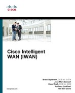
Sizing
ISR-WAAS sizing is based on several factors, including concurrent TCP connections, target WAN bandwidth, and router platform. Optimized connections range from 750 to 2500 connections. Figures 12-3 through 12-6 include the resources and sizing metrics for ISR-WAAS per platform including the platform’s throughput.

The ISR 4451-X offers 1 Gbps performance, upgradable to 2 Gbps via performance license, two physical processors, a four-core processor (one control and three services), and a 10-core data plane processor.
The 4431, shown in Figure 12-4, offers 500 Mbps performance, upgradable to 1 Gbps via performance license. It has two physical processors, four core processors (one control and three services), and six core data plane CPUs.

The Cisco 4351, shown in Figure 12-5, offers 200 Mbps performance, upgradable to 400 Mbps, one physical eight-core CPU with four data plane cores, one control plane core, and three cores dedicated to services. The Cisco 4331 offers 100 Mbps performance, upgradable to 300 Mbps with the same CPU configuration as the 4351.

The 4321, shown in Figure 12-6, offers 50 Mbps performance, upgradable to 100 Mbps, a single four-core CPU with two data plane cores, one control plane core, and one core dedicated to services.
WAAS Performance and Scalability Metrics
The design of a Cisco WAAS solution involves many factors, but performance and scalability metrics are the cornerstone for the solution as a whole while taking into account every individual location. Every component in an end-to-end system has a series of static and dynamic system limits. For instance, a typical application server may be limited in terms of the number of connections it can support, disk I/O throughput, network throughput, CPU speed, or number of transactions per second. Likewise, each Cisco WAAS device has static and dynamic system limits that dictate how and when a particular WAAS device is selected for a location within an end-to-end design.
This section examines the performance and scalability metrics of the Cisco WAAS platform and provides a definition of what each item is and how it is relevant to a localized (per-location) design and an end-to-end system design. The static and dynamic limits referred to are used as a means of identifying which device is best suited to providing services to a particular location in the network. The device may be deployed as an edge device, where it connects to potentially many peer devices in one or more data center locations, or as a core device, where it serves as an aggregation point for many connected edges. WAAS devices can also be deployed as devices to optimize links between data center locations, where devices on each side are realistically core devices.
A fundamental understanding of the performance and scalability metrics is paramount in ensuring a proper design. Although WAAS devices have no concept of the network core or edge, the deployment position within the network has an effect on the type of workload handled by a device and should be considered—primarily as it relates to TCP connection count and peer fan-out (how many peers can connect to a device for the purpose of optimization).
This section also examines each of the performance and scalability system limits, both static and dynamic, that should be considered. These include device memory, disk capacity, the number of optimized TCP connections, WAN bandwidth and LAN throughput, the number of peers (fan-out), and the number of devices managed.
WAAS Design and Performance Metrics
This section discusses design and deployment considerations in deploying WAAS over data center and branch architectures.
Device Memory
The amount of memory installed in a WAAS device dictates the level of performance and scalability the device can provide. As the memory capacity increases, the ability of a WAAS device to handle a larger number of connections, a larger addressable index space for compression, or a longer history of compression data also increases. Having larger amounts of memory also enables the WAAS device to run additional services, such as application acceleration or disk encryption, and positions the device to accept additional features that might be introduced in future software releases. For devices that support flexible memory configuration (such as the WAVE-294, WAVE-594, and WAVE-694), higher levels of WAN bandwidth can be realized, along with an increase in the number of optimized TCP connections that the device can handle concurrently.
Disk Capacity
Optimization services in the Cisco WAAS hardware platforms leverage both memory and disk. From a disk perspective, the larger the amount of available capacity, the larger the amount of optimization history that can be leveraged by the WAAS device during run-time operation. For instance, a WAVE-294 (with 4 GB of DRAM) has 200 GB of physical disk capacity, of which 40 GB is available for use by DRE for compression history. With 40 GB of compression history, one can estimate the length of the compression history given WAN conditions, expected network utilization, and assumed redundancy levels.
Table 12-4 shows how the length of the compression history can be calculated for a particular WAAS device, along with an example. This example assumes a T1 WAN that is 75 percent utilized during business hours (75 percent utilization over 8 hours per day) and 50 percent utilized during nonbusiness hours (16 hours per day). It also assumes that data traversing the network is 75 percent redundant (highly compressible by DRE). This table also assumes a WAVE-294 with 40 GB of allocated capacity for DRE compression history.

The disk capacity available to a WAAS device is split among five major components:
![]() DRE compression history: This capacity is used to store DRE chunk data and signatures.
DRE compression history: This capacity is used to store DRE chunk data and signatures.
![]() CIFS cache: This capacity is pre-allocated.
CIFS cache: This capacity is pre-allocated.
![]() Platform services: This capacity is pre-allocated for operating system image storage, log files, and swap space.
Platform services: This capacity is pre-allocated for operating system image storage, log files, and swap space.
![]() Print services: This capacity is pre-allocated for print spool capacity.
Print services: This capacity is pre-allocated for print spool capacity.
![]() Akamai Connect Object Cache: This capacity is pre-allocated for AKC HTTP object cache capacity.
Akamai Connect Object Cache: This capacity is pre-allocated for AKC HTTP object cache capacity.
Number of Optimized TCP Connections
Each WAAS device has a static number of TCP connections that can be optimized concurrently. Each TCP connection is allocated memory and other resources within the system, and if the concurrently optimized TCP connection static limit is met, additional connections are handled in a pass-through fashion. Adaptive buffering (memory allocation) is used to ensure that more active connections are allocated additional memory, and less active connections are allocated only the memory they require.
The TCP connection limit of each WAAS device can be roughly correlated to the number of users supported by a given WAAS device model, but note that the number of TCP connections open on a particular node can vary based on user productivity, application behavior, time of day, and other factors. It is commonly assumed that a user has 10 to 15 connections open at any given time. If necessary, policies can be adjusted on the WAAS Central Manager to pass through certain applications that may realize only a small benefit from WAAS. This type of change could potentially help increase the number of users who can be supported by a particular WAAS device.
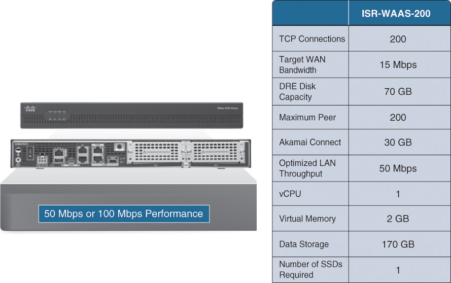
Table 12-5 displays a list of models and the number of optimized connections that are supported on it.
The number of connections a typical user has in a location can be determined by using tools that exist in the operating system of the user’s workstation. Although the estimate of six to ten optimized TCP connections is accurate for the majority of customers, those who wish to more accurately determine how many connections a typical user has open at any given time can do so.
For the data center, the sum of all remote office TCP connections should be considered one of the key benchmarks by which the data center sizing should be done. Note that the largest Cisco WAAS device supports up to 150,000 optimized TCP connections—which is approximately 15,000 users (assuming 10 TCP connections per user). For organizations that need to support a larger number of users or want to deploy the data center devices in a high-availability manner, multiple devices can be used. The type of network interception used determines the aggregate number of optimized TCP connections that can be supported by a group of Cisco WAAS devices deployed at a common place within the data center.
Recommended practice dictates that sites that require high availability be designed with N + 1 availability relative to the number of maximum optimized TCP connections—that is, if 100,000 optimized TCP connections must be supported, the location should have a minimum of two WAVE-7571 devices to support the workload, a third WAVE-7571 device to handle failure of one of the devices, and an interception mechanism such as WCCP or AppNav that supports load balancing of the workload across all three devices.
WAN Bandwidth and LAN Throughput
WAAS devices are not restricted in software or hardware in terms of the amount of WAN bandwidth or LAN throughput supported. However, recommendations are in place to specify which WAAS device should be considered for a specific WAN environment. WAN bandwidth is defined as the amount of WAN capacity that the WAAS device can fully use when employing the full suite of optimization capabilities (this includes DRE, PLZ, TFO, and the other application acceleration capabilities). LAN throughput is defined as the maximum amount of application-layer throughput (throughput as perceived by users and servers) that can be achieved with the particular WAAS hardware model and an equivalent or more powerful peer deployed at the opposite end of the network.
For some deployment scenarios, such as data replication, it is desirable to use the Cisco WAAS devices only for TCP optimization. Cisco WAAS TFO provides a suite of optimizations to better allow communicating nodes to “fill the pipe” (that is, fully leverage the available WAN bandwidth capacity) when the application protocol is not restricting throughput because of application-induced latency. Each Cisco WAAS device has a TFO-only throughput capacity that can be considered when WAAS devices are deployed strictly for TCP optimization. TFO-only optimization is recommended only for situations where compression, redundancy elimination, and application acceleration are not required, and the application throughput has been validated to be hindered only by the performance of the TCP implementation in use. This is common in some data-center-to-data-center applications, such as data replication or data protection, where the traffic that is sent is previously compressed, redundancy eliminated, or encrypted. TFO attempts to fully utilize the available bandwidth capacity but may be hindered by congestion in the network (not enough available bandwidth) or performance impedance caused by application protocol chatter.
Table 12-6 shows the WAN bandwidth supported by each WAAS device model and the maximum LAN-side throughput and targeted WAN bandwidth. Note that other factors can influence these values, and throughput levels can be achieved only when the link capacity available supports such a throughput level. For instance, a LAN throughput maximum of 150 Mbps is not possible on a Fast Ethernet connection; rather, a Gigabit Ethernet connection is required. Similarly, for throughput speeds of more than 1 Gbps, multiple 1 Gbps interfaces must be used.

The amount of bandwidth required per site is the sum of available WAN capacity that can be used at that site and not the sum of all WAN bandwidth for every connected peer. For instance, if a branch office has four bundled T1 links (totaling 6 Mbps of aggregate WAN throughput) but only two are used at any given time (high-availability configuration), a device that supports 3 Mbps or more is sufficient to support the location. Similarly, if a data center has four DS-3 links (totaling 180 Mbps of aggregate WAN throughput) but uses only three at a time (N + 1 configuration), a device that supports 135 Mbps of WAN bandwidth or more is sufficient to support that location.
The WAN throughput figures given in Table 12-6 are (as discussed previously) not limited in hardware or software. In some cases, the WAN throughput that a device achieves may be higher than the values specified here. Any WAAS system can optimize up to the maximum of its capacity until overload conditions arise. During overload conditions, new connections are not optimized. Existing connections are optimized to the greatest degree possible by the system. Should scalability beyond the capacity of a single device be required, multiple devices can be deployed. The maximum number of optimized TCP connections assumes that MAPI AO is disabled, and therefore the connection reservation requirement is removed. If MAPI AO is enabled, a small number of connections are put into a reservation pool to account for the multiple connections associated with a single user flow. Target WAN bandwidth is not limited in software or by any other system limit but rather is provided as guidance for deployment sizing purposes.
Target WAN bandwidth is a measure of the optimized/compressed throughput WAAS can support; this value is taken at approximately 70 percent compression. Maximum optimized LAN throughput numbers are measured with five to ten high-throughput connections optimized over a Gigabit network with minimal latency. LAN throughput may be affected by factors outside of WAAS; for example, the router that is doing the redirection may become the bottleneck. Actual results depend on the use case.
Number of Peers and Fan-out Each
Cisco WAAS devices have a static system limit in terms of the number of concurrent peers with which they can actively communicate at any given time. When designing for a particular location where the number of peers exceeds the maximum capacity of an individual device, multiple devices can be deployed, assuming that an interception mechanism that uses load balancing is employed (such as WCCPv2 or AppNav). In cases where load balancing is used, TCP connections are distributed according to the interception configuration, thereby allowing for near-linear scalability increases in connection count, peer count, and WAN bandwidth as devices are added to the pool. Load-balancing interception techniques are recommended when multiple devices are used in a location. Peer relationships are established between Cisco WAAS devices during the automatic discovery process on the first connection optimized between the two devices. These peer relationships time out after 10 minutes of inactivity (that is, no active connections are established and optimized between two peers for 10 minutes). Each WAAS device supports a finite number of active peers, and when the peer relationship is timed out, that frees up peering capacity that can be reused by another peer. Data stored in the DRE compression history remains intact even if a peer becomes disconnected because of inactivity, unless the DRE compression history becomes full. In cases where the DRE compression history becomes full, an eviction process is initiated to remove the oldest set of data to make room for new data.
Table 12-7 shows the maximum number of concurrent peers supported per WAAS platform. If peers are connected beyond the allocated limit, the WAVE permits the connections to be established and gracefully degrades performance as needed. Connections associated with peers in excess of the maximum fan-out ratio are able to use the existing compression history but are not able to add new chunks of data to it. The result is lower effective compression ratios for the connections using peers that are in excess of the specified fan-out ratio.

The number of peers supported by a device is typically the last factor that should be considered when sizing a solution for a particular location. The primary reason is that the WAN capacity or number of connections supported on the device (at the maximum concurrent peers specification) is generally higher than what the device can support. For instance, although a WAVE-294 can support up to 100 peers, even if those peers are the WAVE-694 (each supporting 2500 optimized TCP connections), it is not able to handle the 2500 possible optimized TCP connections that all WAVE-694s are attempting to optimize with it. It is best to size a location first based on WAN bandwidth capacity and TCP connections, and in most cases only a simple validation that the number of peers supported is actually required.
Central Manager Sizing
Each Cisco WAAS deployment must have at least one Cisco WAAS device deployed as a Central Manager. The Central Manager is responsible for system-wide policy definition, synchronization of configuration, device monitoring, alarming, and reporting.
The Central Manager can be deployed as appliances or a virtual instance and can be deployed in an active/standby fashion. When a certain type of WAAS device is configured as a Central Manager, it is able, based on the hardware or virtual platform selected for the Central Manager, to manage a maximum number of WAAS devices within the topology.
In high-availability configurations, each Central Manager WAVE or virtual instance should be of the same hardware configuration or managed node count. Although hardware disparity between Central Manager WAVEs works, it is not a recommended practice given the difference in the number of devices that can be managed among the WAVE hardware models. It should be noted that standby Central Managers receive information in a synchronized manner identically to how accelerator WAAS devices do. Table 12-8 shows the maximum number of managed nodes that can be supported by each WAAS appliance when configured as a Central Manager.

Use of multiple WAAS devices configured as Central Manager devices does not increase the overall scalability in terms of the number of devices that can be managed. To manage a number of devices greater than the capacities given in Table 12-8, multiple autonomous Central Managers are needed. For instance, in an environment with 3000 devices, two separate instances of Central Manager are required, and each instance can be composed of a single device or multiple devices deployed in a high-availability primary/standby configuration.
Licensing
Licenses are not enforced in WAAS; however, licenses can be applied only to platforms that support the particular license in question. The Enterprise License is included with all WAAS device purchases. The Enterprise License allows a WAAS device to apply all the WAN and application acceleration techniques. WAAS devices that act as Central Managers also require the Enterprise License. To deploy both the ISR-WAAS and the AppNav-XE components, the Application Experience (appxk9 package) License is required.
Note
Akamai Connect Licensing is an add-on license based on connection count of the WAAS node on which it is being deployed.
Cisco WAAS Operational Modes
By default, WAAS transparently (by preserving the packet’s original source/destination IP addresses and TCP ports) sets up a new TCP connection to a peer WAVE, which can cause firewall traversal issues when a WAAS device tries to optimize traffic. If a WAVE device is behind a firewall that prevents traffic optimization, Directed Mode can be used. In Directed Mode, all TCP traffic that is sent to a peer WAVE is encapsulated in UDP, which allows a firewall to either bypass the traffic or inspect the traffic (by adding a UDP inspection rule).
Transparent Mode
By default, WAAS handles traffic transparently by preserving the packet’s original source/destination IP addresses and TCP ports. The Transparent Mode of operation allows for end-to-end traffic visibility, which eases interoperability with existing network-based QoS, access control, and performance management/reporting capabilities.
Directed Mode
WAAS version 4.1 added an alternative mode of operation called Directed Mode. Directed Mode transports optimized connections using a nontransparent (UDP-encapsulated) mechanism between two WAAS devices. The source and destination IP addresses of the encapsulated packet are the IP addresses of the WAEs themselves.
Directed Mode relies on the auto-discovery process to establish the peer relationship between two WAEs. This means that Directed Mode does not bypass any security measures. Initial TCP traffic flows between client and server must pass through any firewalls before traffic can be optimized by WAAS in Directed Mode. After the auto-discovery process succeeds, the server-side WAE sends a TCP reset (RST) packet toward the client-side WAE to clear out the connection state on any intermediate devices between the WAEs. Future traffic for the connection is then encapsulated in a UDP header with a configurable source and destination port of 4050.
Interception Techniques and Protocols
There are two approaches to leveraging the network infrastructure to intercept and redirect traffic to WAAS for optimization. The first method relies on interception protocols or routing configuration used by the networking components (routers and switches) to selectively intercept traffic and redirect it to the WAAS infrastructure. This method is referred to as off-path interception. The most common method for off-path network interception is WCCPv2.
The second method places the WAVE physically inline between two network devices, most commonly a router and a LAN switch. All traffic between the two network devices passes through the WAVE, which can then selectively intercept traffic for optimization. This method is referred to as in-path interception, because the WAVE is physically placed in the data path between the clients and servers.
This section discusses both off-path (WCCPv2) and in-path (inline) interception in detail. It also discusses other interception options for specific use cases, such as PBR and AppNav. These additional interception options add to the flexibility with which WAAS can be integrated into existing network infrastructures of all sizes.
Web Cache Communication Protocol
This section does not provide an exhaustive reference for the WCCPv2 protocol. Rather, it provides enough information about the protocol background and concepts to enable you to understand the WCCPv2 implementation in Cisco WAAS.
WCCP is a transparent interception protocol developed by Cisco Systems, Inc., in 1997. WCCP is a control plane protocol that runs between devices running Cisco IOS and WCCP “clients” such as WAAS. The protocol enables the network infrastructure to selectively intercept traffic based on IP protocol and transport protocol port numbers and redirect that traffic to a WCCP client. WCCP is considered transparent, because it allows for local interception and redirection of traffic without any configuration changes to the clients or servers. WCCP has built-in load-balancing, scalability, fault tolerance, and service assurance (fail-open) mechanisms.
The current version, WCCPv2, is used by Cisco WAAS to transparently intercept and redirect all TCP traffic, regardless of port. The following section describes the basic WCCPv2 concepts and how they are specifically used by Cisco WAAS.
WCCP Service Groups
The routers and WAVEs participating in the same service constitute a service group. A service group defines a set of characteristics about what types of traffic should be intercepted, as well as how the intercepted traffic should be handled. There are two types of service groups:
![]() Well-known services, also referred to as static services, have a fixed set of characteristics that are known by both IOS and WCCPv2 client devices. There is currently a single well-known service called Web-Cache. This service redirects all TCP traffic with a destination port of 80.
Well-known services, also referred to as static services, have a fixed set of characteristics that are known by both IOS and WCCPv2 client devices. There is currently a single well-known service called Web-Cache. This service redirects all TCP traffic with a destination port of 80.
![]() Dynamic services are initially known only to the WCCPv2 clients within the service group.
Dynamic services are initially known only to the WCCPv2 clients within the service group.
The characteristics of the service group are communicated to the IOS devices by the first WCCPv2 client device to join the service group. A unique service ID, which is a number from 0 to 255, identifies service groups. Service IDs 0 to 50 are reserved for well-known services.
The WCCPv2 implementation in WAAS supports a single dynamic WCCPv2 service, the TCP-Promiscuous service. Although referred to in WAAS as a single service, the TCP-Promiscuous service is in fact two different services. The two service IDs enabled with the TCP-Promiscuous service are 61 and 62. These are the two service group IDs that are configured in IOS when using WCCPv2 with WAAS.
Two different service groups are used because by default both directions (client to server and server to client) of a TCP connection must be transparently intercepted. To optimize a connection, WAAS must see both directions of the connection on the same WAE. Not only does WAAS intercept the connection in both directions, but it also intercepts the connection on both sides of the WAN link. Because the packet Layer 3 and Layer 4 headers are preserved, transparent interception is used on both sides of the WAN in both directions to redirect connections to the WAAS infrastructure for optimization. Figure 12-7 shows a basic topology with WCCPv2 interception configured for WAAS.

By default, service group 61 hashes on the source IP address and service group 62 hashes on the destination IP address. Later, this chapter discusses the significance of the hash key used in each service group. By default, the spoof-client-ip feature is enabled for both services. This is the WCCPv2 feature that allows WAAS to handle optimized traffic transparently. Traffic forwarded to the WAE uses the same source and destination IP addresses and TCP ports as when it entered the WAVE.
Forwarding and Return Methods
WCCPv2 supports different methods of forwarding redirected traffic from an IOS router or switch to a WAVE, and for the WAVE to return traffic to the IOS router/switch for forwarding. These methods are referred to as the forwarding and return methods and are negotiated between IOS and the WAVE when a WAVE joins the service group. The forwarding method defines how traffic that is being redirected from IOS to the WAVE is transmitted across the network.
![]() The first forwarding method, GRE forwarding, encapsulates the original packet in a WCCP GRE header with the destination IP address set to the target WAVE and the source IP address set to the WCCPv2 router ID of the redirecting router. When the WAVE receives the GRE-encapsulated packet, the GRE header is removed, and the packet is processed.
The first forwarding method, GRE forwarding, encapsulates the original packet in a WCCP GRE header with the destination IP address set to the target WAVE and the source IP address set to the WCCPv2 router ID of the redirecting router. When the WAVE receives the GRE-encapsulated packet, the GRE header is removed, and the packet is processed.
![]() The second forwarding method, L2 forwarding, simply rewrites the destination MAC address of the packet being redirected to equal the MAC address of the target WAVE. This forwarding method assumes that the WAE is Layer 2 adjacent to the redirecting router. One of the benefits of L2 forwarding is that it allows the WCCPv2 redirection to occur in hardware.
The second forwarding method, L2 forwarding, simply rewrites the destination MAC address of the packet being redirected to equal the MAC address of the target WAVE. This forwarding method assumes that the WAE is Layer 2 adjacent to the redirecting router. One of the benefits of L2 forwarding is that it allows the WCCPv2 redirection to occur in hardware.
The return method defines how traffic should be returned from the WAVE to the redirecting router/switch for normal forwarding. As with the forwarding method, there are two different return methods:
![]() In GRE return, egress traffic from the WAE using GRE return is encapsulated using WCCP GRE, with a destination IP address of the WCCPv2 router ID and a source IP address of the WAVE itself. When the WCCPv2-enabled router receives the returned packet, the IP GRE header is removed and the packet is forwarded normally. WCCPv2 in IOS knows not to re-intercept traffic returned to it using GRE return.
In GRE return, egress traffic from the WAE using GRE return is encapsulated using WCCP GRE, with a destination IP address of the WCCPv2 router ID and a source IP address of the WAVE itself. When the WCCPv2-enabled router receives the returned packet, the IP GRE header is removed and the packet is forwarded normally. WCCPv2 in IOS knows not to re-intercept traffic returned to it using GRE return.
![]() L2 return returns traffic to the WCCPv2-enabled router by rewriting the destination MAC address of the packet to equal the MAC address of the WCCPv2-enabled router. Whether the negotiated return method is used by WAAS to inject traffic back into the network infrastructure is determined by the configured egress method.
L2 return returns traffic to the WCCPv2-enabled router by rewriting the destination MAC address of the packet to equal the MAC address of the WCCPv2-enabled router. Whether the negotiated return method is used by WAAS to inject traffic back into the network infrastructure is determined by the configured egress method.
Load Distribution
When multiple WAVEs exist in a service group, WCCPv2 automatically distributes redirected traffic across all WAVEs in the service group. When traffic passes through an IOS device with WCCPv2 redirection configured, the IOS device assigns traffic for that connection to a bucket. Each bucket is assigned to a specific WAVE. The method that determines to which bucket traffic is assigned, which determines how traffic is distributed across multiple WAEs within a service group, is called the assignment method.
The bucket assignments are communicated from the lead WAE to all IOS devices in the service group. The assignment method can use either a hashing or a masking scheme and is negotiated between IOS and WAVE during the formation of the service group.
Hash assignment, which is the default assignment method, performs a bitwise hash on a key identified as part of the service group. In WAAS, the hash key used for service group 61 is the source IP address, whereas the hash key used for service group 62 is the destination IP address. The hash is not configurable and is deterministic in nature. This means that all the routers within the same service group make the same load-balancing decision given the same hash key. This deterministic behavior is what allows WCCPv2 to support asymmetric traffic flows, so long as both directions of the flow pass through WCCPv2-enabled IOS devices in the same service group. Hash assignment uses 256 buckets.
The second assignment method is called mask assignment. With mask assignment, the source IP address, destination IP address, source port, and destination port are concatenated and ANDed with a 96-bit mask to yield a value. The resulting 96-bit value is compared to a list of mask/value pairs. Each mask/value pair is associated with a bucket, and each bucket is in turn assigned to a WAVE. Unlike hash assignment, the number of buckets used with mask assignment depends on the number of bits used in the mask. By default, WAAS uses a mask of 0x1741. This results in 26 buckets that can be assigned across the WAVEs in a service group.
Failure Detection
After a WAVE has successfully joined a service group, a periodic keepalive packet is sent every 10 seconds (by default) from the WAVE to each router in the service group. The keepalive mechanism occurs independently for each configured service group. If a router in the service group has not received a keepalive packet from the WAVE in 2.5 times the keepalive interval, the router unicasts a removal query (RQ) message to that WAVE requesting that it immediately respond. If no response is received within 5 seconds, for a total of 30 seconds (by default) since the last keepalive message from the WAVE, the WAVE is considered offline and is removed from the service group.
Flow Protection
When a WAVE (re)joins the service group, a new redirect assignment (RA) message is generated by the lead WAVE. The RA message instructs routers how to reallocate load redistribution between other WAVE devices. When the new WAVE begins receiving redirected traffic from the routers in the service group, it does one of two things, depending on whether or not the redirected traffic is associated with a new TCP connection or part of an existing connection.
Traffic associated with newly established connections is evaluated against the ATP and processed normally by the WAVE. Traffic associated with existing connections is forwarded directly to the WAE that previously owned the bucket for that connection. This WCCPv2 mechanism is called flow protection and is enabled by default. Flow protection allows existing connections to continue to be optimized even when the traffic assignments for the WAEs in a service group change.
Scalability
With WCCPv2, each service group can support up to 32 routers and 32 WAEs. This means that a single service group can support N × 32 concurrent optimized TCP connections, where N is the number of concurrent optimized TCP connections supported by the largest WAE model. Each WAE in the service group is manually configured with the IP address of each router in the service group. The WAE then uses unicast packets to exchange WCCPv2 messages with each router. It is not required that the routers in the service be manually configured with the IP address of each WAE in the service group. Each router listens passively for WCCPv2 messages from the WAEs in the service group and responds only as a result of receiving those messages.
The WAVE in the service group with the lowest IP address is elected as the “lead” WAVE. The lead WAVE is responsible for communicating the list, or view, of the routers in the service group to the service group routers. The lead WAVE is also responsible for informing the routers how traffic should be distributed across WAVEs in the service group through the use of RA messages. Upon receiving the view of the routers in the service group from the lead WAVE, each router responds individually with a router view. The router view contains a list of each WAVE with which the router is currently communicating. What is implied is that the routers in the service group do not communicate directly with each other; they learn about each other through the router view advertised by the WAVE. Likewise, the WAEs in a service group do not communicate directly; they learn about each other from the WAVE view advertised by the routers.
Redirect Lists
WCCPv2 redirect lists are used for deployments that may want to limit redirection to specific types of traffic. WCCP redirect lists are also useful for restricting transparent interception during proof of concept or pilot testing to a limited set of hosts and/or applications.
A WCCPv2 redirect list is a standard or extended IOS access list that is associated with a WCCPv2 service. Traffic passing through an interface on the router with WCCPv2 redirection configured must match not only the protocol/port specified as part of the service group, but also a permit entry in the redirect list. Packets that match the service group protocol/port criteria but do not match a permit entry in the redirect list are forwarded normally.
Service Group Placement
The placement of service groups 61 and 62 should not be overlooked in a WAAS deployment. The placement refers to which IOS interfaces are configured with service group 61 and which interfaces are configured with service group 62.
The direction in which interception occurs on the interfaces is important. Interception is configured in either the inbound or outbound direction. Inbound redirection evaluates traffic against the service group criteria as it enters the interface of a router, and outbound redirection evaluates traffic after it has already been switched through the router and is exiting the egress (based on routing table lookup) interface. In most deployments, service group 61 should be configured on the client-facing interfaces. The client-facing interfaces may differ depending on whether you are configuring WCCP in a remote branch office or in the data center.
For example, when deploying WCCPv2 on a remote office WAN router, service group 61 is configured to intercept a client request. Configuring group 61 inbound on the router’s LAN interface or outbound on the router’s WAN interface accomplishes this. By using service group 61 to intercept traffic in the client-to-server direction, WCCP performs load balancing in the service group based on the client IP address.
For the reverse direction of the connection, service group 62 is used. Service group 62 is configured in the opposite direction of service group 61. Because traffic is flowing in the reverse direction (server to client), the load balancing also occurs on the client IP address.
Egress Methods
Cisco WAAS provides several options for handling egress traffic received on intercepted connections. These options allow for flexibility when determining where to integrate WAAS into the existing network infrastructure and help preserve the original path selection for traffic flows.
The first egress method available in Cisco WAAS is IP forwarding. Egress traffic received on intercepted connections is forwarded based on the configuration of the local WAVE routing table, which typically means that traffic is forwarded to the configured default gateway. In addition to supporting a single default gateway, WAAS supports up to 1024 static routes. Static routes are configured with a next-hop IP address of a directly connected interface; recursive next-hop IP addresses are not supported. Although it is possible to configure multiple static routes for the same destination, there is no support for ECMP. Only a single route is installed in the routing table at a time.
Note
Traffic originating from the WAVE itself also uses IP forwarding, regardless of the egress method configuration. The IP forwarding egress method is suited for basic topologies where only a single egress path for traffic exists.
The second egress method option available is called WCCP generic routing encapsulation (GRE). This technique makes it possible to support redundant routers and router load balancing. The GRE tunnels are created automatically to process outgoing GRE-encapsulated traffic for WCCP. They appear when a WAVE requests GRE redirection. The GRE tunnel is not created directly by WCCP but indirectly via a tunnel API. Packet redirection is handled entirely by the redirecting device in software. WCCP has no direct knowledge of these tunnel interfaces but knows enough to cause packets to be redirected to them. This results in the appropriate encapsulation being applied, after which the packet is then sent to the WAVE device. WAAS makes a best effort to return frames back to the router from which they arrived.
The third option available is called generic GRE. Generic GRE functions in a similar manner to WCCP GRE return but leverages a traditional GRE tunnel interface in IOS to receive egress traffic from one or more WAVEs in the service group. The generic GRE egress method is designed specifically to be used in deployments where the router or switch has hardware-accelerated processing of GRE packets. To use the generic GRE egress method, a GRE tunnel interface must be created on each router.
With generic GRE return, a tunnel interface is configured in IOS on all WCCP-enabled routers in the service group. The tunnel interface is configured as either a point-to-point or a point-to-multipoint interface.
Policy-Based Routing (PBR)
Policy-based routing provides another alternative for transparent interception with WAAS, although it is less commonly deployed than WCCPv2 and inline interception. PBR can be used in situations where customers are unable to run WCCPv2 or inline interception.
PBR functions in a similar manner to WCCPv2, in that a router/switch running Cisco IOS is configured to intercept interesting traffic and redirect it to a WAE. Unlike WCCPv2, no configuration is required on the WAE to support interception using PBR via a routing policy. The following steps are used to configure PBR:
1. Create an access list to define interesting traffic for redirection.
2. Create a route map that matches the ACL created in Step 1 and sets an IP next-hop address of the target WAE.
3. Apply the route map to interfaces through which client and server traffic traverses.
Example 12-1 provides the basic PBR configuration used to redirect all TCP traffic to a single WAVE.
Example 12-1 Policy-Based Routing Configuration
access-list 175 permit tcp any any
!
route-map WAAS-Redirect 10
match ip address 175
set ip next-hop 10.10.20.2
!
interface Tunnel 100
description ** WAN Interface **
ip add 192.168.40.1 255.255.255.252
ip policy route-map WAAS-Redirect
!
interface GigabitEthernet0/0
no ip address
duplex auto
speed auto
!
interface GigabitEthernet0/0.1
description ** Branch Client VLAN **
encapsulation dot1q 10
ip address 10.10.10.1 255.255.255.0
ip policy route-map WAAS-Redirect
!
interface GigabitEthernet0/0.20
description ** Branch WAVE VLAN **
ip address 10.10.20.1 255.255.255.0
Because PBR evaluates only traffic entering an interface, the route map entries are configured on both the ingress and egress interfaces. This is the equivalent of using only inbound redirection with WCCPv2. The set ip next-hop command in the route map is configured with the IP address of the WAVE. By default, PBR does not validate the availability of the IP address specified as the next-hop address. As long as the next-hop address exists in the routing table, the route map entry is applied. On some platforms and software versions, Cisco Service Assurance Agent (SAA) can be used to track the availability of the next-hop IP address.
If the next-hop address becomes unreachable, traffic matching the route map entry is forwarded normally using the routing table. Another difference between WCCPv2 and PBR is that PBR does not perform automatic load distribution and failover when multiple WAEs exist. The first next-hop IP address configured in the route map is used until it becomes unavailable. Only at that point is traffic redirected to a secondary next-hop IP address in the route map.
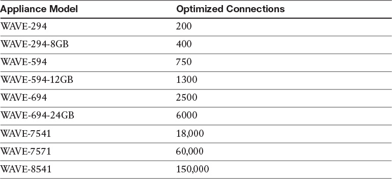
Inline Interception
An alternative to the various off-path interception mechanisms is to place the WAE physically inline between two network elements, such as a WAN access router and a LAN switch. Figure 12-8 shows a basic topology with the WAE deployed physically inline.
Physical inline interception is an attractive option for situations where it is not possible or ideal to run WCCPv2. Common scenarios for inline interception are when access to the networking equipment at a site is provided and managed by a managed service provider (MSP). Because a logical interception technique cannot be configured on the device, physical inline interception can be used to provide the benefits.
To support physical inline interception, the WAE requires a separate inline module. The inline module is a two- or four-port, fail-to-wire network interface card (NIC) with each pair of ports in a unique inline group. Each inline group has a synchronous pair of inline ports that interconnect two network elements. Traffic entering one inline port is optimized by WAAS (when applicable) and switched out the opposite inline port in the same group. The inline group functions like a transparent Layer 2 bridge.
On platforms that support a four-port inline module, the WAE can support designs where multiple paths out of a site exist for redundancy and load sharing. Each unique path is connected to the WAE through a separate inline group. Figure 12-9 shows a sample remote site topology with multiple WAN routers and a single WAE deployed with inline interception.

As the arrows in Figure 12-9 indicate, traffic can enter or leave the site through either router. Even though the same flow enters the site through one inline group and exits the site through another inline group, the connection is still optimized. The optimized connection state is not tied to a physical interface but is tracked for the WAE as a whole independent of the interfaces traversed by the traffic.
Each inline group functions in one of two operating modes:
![]() Interception: Traffic entering the inline group is evaluated against the ATP for optimization.
Interception: Traffic entering the inline group is evaluated against the ATP for optimization.
![]() Bypass: All traffic entering the inline group is bridged without any optimization.
Bypass: All traffic entering the inline group is bridged without any optimization.
The bypass operating mode is designed to enable the WAVE to continue passing traffic if the WAVE loses power. A keepalive mechanism between the network drivers and the inline module determines if the WAVE is functioning properly and can optimize connections.
The keepalive frequency is configurable between 1 and 10 seconds. The default failover timer is set to 3 seconds. The transition between intercept operating mode and bypass operating mode does cause a momentary loss of line protocol. If one or more of the inline ports are connected to a LAN switch, this transition in interface state can cause the Spanning Tree Protocol (STP) recalculation. To prevent the STP calculation from interrupting traffic forwarding, the switchport connected to the inline module on the WAE should have the STP PortFast feature enabled.
AppNav Overview
The AppNav model is well suited to data center deployments and addresses many of the challenges of WAN optimization in this type of environment. Cisco AppNav technology enables customers to virtualize WAN optimization resources in the data center by pooling them into one elastic resource.
The AppNav solution has the ability to scale up to available capacity by taking into account WAAS device utilization as it distributes traffic among nodes. It integrates transparently with Cisco WAAS physical and virtual network infrastructure, supporting more than a million connections, providing significant investment protection for existing network design objectives as well as the capability to expand the WAN optimization service to meet future demands. Also, the solution provides for high availability of optimization capacity by monitoring node overload and liveliness and by providing configurable failure and overload policies. Because the Cisco AppNav solution enables organizations to pool elastic resources, it lays the foundation for migration to cloud services as well.
AppNav is a hardware and software solution that simplifies network integration of WAN optimization. WAAS version 5.0 introduces a new AppNav deployment model that greatly reduces dependency on the intercepting switch or router by taking on the responsibility of distributing traffic among WAAS devices for optimization. An AppNav device can be either a WAAS appliance with a Cisco AppNav Controller (ANC) Interface Module or a Cisco router with Cisco IOS XE Release 3.9 (or later) running AppNav-XE (known as an AppNav-XE device). Figure 12-10 illustrates the basic components of an AppNav Cluster.

WAAS appliances with AppNav Controller Interface Modules operate in a special AppNav Controller mode with AppNav policies controlling traffic flow to WAAS devices doing optimization. Cisco AppNav technology is deployed on the new-generation Cisco WAVE appliances in the data center or private cloud. The 1 Gbps solution is offered with two types of IOMs in copper and Small Form-Factor Pluggable (SFP) form factors that can be plugged into Cisco WAVE-8541, 8571, 7541, and 694 devices. These solutions can run purely as Cisco AppNav solutions or as Cisco AppNav and Cisco WAAS on the same platform. The 10 Gbps package runs exclusively in Cisco AppNav mode and consists of the chassis (WAVE-594) as well as AppNav IOM. The AppNav 10 Gbps appliance provides high performance and high availability (dual power supply) in a single form factor. Both 1 Gbps and 10 Gbps solutions run Cisco WAAS software version 5.0 or later.
An AppNav-XE device, which is a Cisco router or virtual Cloud Services Router with virtual AppNav capability, can interoperate with other WAAS devices that are acting as WAAS nodes. An AppNav-XE device acts as an AppNav Controller that distributes traffic to other WAAS devices acting as WAAS nodes that optimize the traffic. AppNav-XE can run on router platforms that use IOS XE. These platforms are currently the ISR 4000, Cloud Services Router (CSR) 1000V, and Aggregation Services Router (ASR) 1000 Series routers, starting in IOS XE version 3.9.
Note
ANCs on different platforms cannot be in the same AppNav Cluster.
AppNav Cluster Components
The following section describes the components of the AppNav Cluster:
![]() AppNav Controller Group (ANCG, or ACG on an XE-based router): A group of AppNav Controllers that together provide the necessary intelligence for handling asymmetric flows and providing high availability. The ANCG is configured on the ANC. An ANCG can have up to eight WAAS appliance-based ANCs. An ACG can have four AppNav-XE-based ANCs (which must be on the same router platform with the same memory configuration). For example, an ASR1002 and ASR1004 cannot be in the same ANC.
AppNav Controller Group (ANCG, or ACG on an XE-based router): A group of AppNav Controllers that together provide the necessary intelligence for handling asymmetric flows and providing high availability. The ANCG is configured on the ANC. An ANCG can have up to eight WAAS appliance-based ANCs. An ACG can have four AppNav-XE-based ANCs (which must be on the same router platform with the same memory configuration). For example, an ASR1002 and ASR1004 cannot be in the same ANC.
![]() WAAS node (WN), or service node (SN) on the router: A WAAS optimization engine (WAE or WAVE appliance, network module, or vWAAS instance) that optimizes and accelerates traffic according to the optimization policies configured on the device. There can be up to 32 WNs in the cluster. (In the CLI and on the router, a WAAS node is also known as a service node.)
WAAS node (WN), or service node (SN) on the router: A WAAS optimization engine (WAE or WAVE appliance, network module, or vWAAS instance) that optimizes and accelerates traffic according to the optimization policies configured on the device. There can be up to 32 WNs in the cluster. (In the CLI and on the router, a WAAS node is also known as a service node.)
![]() AppNav Cluster: The group of all ANC and WN devices within a cluster.
AppNav Cluster: The group of all ANC and WN devices within a cluster.
![]() AppNav context: The topmost entity that groups together one ANCG, one or more WAAS node groups (WNGs), and an associated AppNav policy. The AppNav context is configured on the ANC. When using a WAAS appliance ANC, there is only one AppNav context, but when using an AppNav-XE ANC, you can define up to 32 AppNav contexts, which are associated with different VRF instances defined on the router.
AppNav context: The topmost entity that groups together one ANCG, one or more WAAS node groups (WNGs), and an associated AppNav policy. The AppNav context is configured on the ANC. When using a WAAS appliance ANC, there is only one AppNav context, but when using an AppNav-XE ANC, you can define up to 32 AppNav contexts, which are associated with different VRF instances defined on the router.
Class Maps
AppNav class maps classify traffic according to one or more of the following match conditions:
![]() Peer device ID matches traffic from one peer WAAS device, which can be handling traffic from a single site or a group of sites.
Peer device ID matches traffic from one peer WAAS device, which can be handling traffic from a single site or a group of sites.
![]() Source IP, and/or destination IP, and/or destination port matches traffic from a specific application.
Source IP, and/or destination IP, and/or destination port matches traffic from a specific application.
![]() The class default class map (or APPNAV-class-default on AppNav-XE clusters) is a system-defined default class map that is defined to match any traffic. By default, it is placed in the last rule in each policy to handle any traffic that is not matched by other classes.
The class default class map (or APPNAV-class-default on AppNav-XE clusters) is a system-defined default class map that is defined to match any traffic. By default, it is placed in the last rule in each policy to handle any traffic that is not matched by other classes.
AppNav Policies
The AppNav policy is a flow distribution policy that allows you to control how ANCs distribute traffic to the available WNs. The AppNav policy consists of class maps that classify traffic according to one or more match conditions and a policy that contains rules that specify distribution actions to WNGs for each of the classes.
AppNav Site Versus Application Affinity
A WNG can be provisioned for serving specific peer locations (site affinity) or applications (application affinity) or a combination of the two. Using a WNG for site or application affinity provides the following advantages:
![]() Site affinity gives you the ability to always send all traffic from one site to a specific WNG, which allows you to reserve optimization capacity for critical sites and to improve compression performance through better utilization of the DRE cache. Traffic from any location, not just a single site, can be matched in a class map and associated with a WNG.
Site affinity gives you the ability to always send all traffic from one site to a specific WNG, which allows you to reserve optimization capacity for critical sites and to improve compression performance through better utilization of the DRE cache. Traffic from any location, not just a single site, can be matched in a class map and associated with a WNG.
![]() Application affinity gives you the ability to always send certain application traffic to a specific WNG, which allows you to reserve optimization capacity for different applications depending on business priorities.
Application affinity gives you the ability to always send certain application traffic to a specific WNG, which allows you to reserve optimization capacity for different applications depending on business priorities.
AppNav IOM
Cisco AppNav enables you to easily add WAN optimization capacity to the data center without having to make any changes to network configurations. AppNav allows for the expansion of WAN optimization capacity without any service disruption, regardless of whether it is deployed inline or off the path. It integrates transparently with Cisco WAAS physical and virtual network infrastructure. Because the Cisco AppNav solution enables organizations to pool elastic resources, it lays the foundation for migration to cloud services as well.
AppNav Controller Deployment Models
AppNav Controllers can be deployed in two ways:
![]() In-path: The ANC is physically placed between one or more network elements, enabling traffic to traverse a bridge group configured on the device in inline mode. A bridge group consists of two or more physical or logical (port channel) interfaces.
In-path: The ANC is physically placed between one or more network elements, enabling traffic to traverse a bridge group configured on the device in inline mode. A bridge group consists of two or more physical or logical (port channel) interfaces.
![]() Off-path: The ANC works with the network infrastructure to intercept traffic through the WCCP. The ANC operates in WCCP interception mode with one physical or logical (standby or port channel) interface configured with an IP address.
Off-path: The ANC works with the network infrastructure to intercept traffic through the WCCP. The ANC operates in WCCP interception mode with one physical or logical (standby or port channel) interface configured with an IP address.
The ANC provides the same features in both in-path and off-path deployments. In either case, only ANCs participate in interception from the switch or router. The ANCs then distribute flows to WNs using a consistent and predictable algorithm that considers configured policies and WN utilization.
Cisco AppNav technology is a complementary technology to WCCP. WCCP provides both redirection and load distribution capabilities and is the technology most widely used to deploy WAN optimization today. The Cisco AppNav module allows customers to offload the load distribution function from the WCCP router, allowing the router to focus on traffic interception and redirection to a single WAN optimization pool.
AppNav Controller Interface Modules
A WAAS appliance operating as an ANC requires a Cisco AppNav Controller Interface Module, which is similar to a standard WAVE appliance interface module but contains additional hardware, including a network processor and high-speed ternary content addressable memory (TCAM), to provide intelligent and accelerated flow handling.
The following AppNav Controller Interface Modules (IOMs) are supported:
![]() 1 GB copper 12-port AppNav Controller Interface Module (APNV-GE-12T)
1 GB copper 12-port AppNav Controller Interface Module (APNV-GE-12T)
![]() 1 GB SFP 12-port AppNav Controller Interface Module (APNV-GE12SFP)
1 GB SFP 12-port AppNav Controller Interface Module (APNV-GE12SFP)
![]() 10 GB SFP+ four-port AppNav Controller Interface Module (APNV-10GSFP)
10 GB SFP+ four-port AppNav Controller Interface Module (APNV-10GSFP)
Table 12-9 provides additional details about the AppNav IOMs that are available.

AppNav IOM Interfaces
Interfaces on the AppNav Controller Interface Module can have three functions:
![]() Interception: Used to receive traffic intercepted from the network and egress traffic to the network. The interception interface is implied based on the AppNav Controller placement and does not require explicit configuration for this function.
Interception: Used to receive traffic intercepted from the network and egress traffic to the network. The interception interface is implied based on the AppNav Controller placement and does not require explicit configuration for this function.
![]() Distribution: Used to distribute traffic to the WNs and receive egressed traffic from the WNs. The distribution interface is explicitly configured as the cluster interface for intra-cluster traffic and must be assigned an IP address.
Distribution: Used to distribute traffic to the WNs and receive egressed traffic from the WNs. The distribution interface is explicitly configured as the cluster interface for intra-cluster traffic and must be assigned an IP address.
![]() Management: A management interface can be optionally and exclusively designated for management traffic and isolated from the normal data path. Cisco recommends using one of the appliance’s built-in interfaces for management traffic and reserving the high-performance interfaces on the AppNav Controller Interface Module for interception and distribution.
Management: A management interface can be optionally and exclusively designated for management traffic and isolated from the normal data path. Cisco recommends using one of the appliance’s built-in interfaces for management traffic and reserving the high-performance interfaces on the AppNav Controller Interface Module for interception and distribution.
Guidelines and Limitations
You should use separate interfaces for interception and distribution for best performance, but you can use the same interface for both functions. AppNav Controller Interface Modules support port channel and standby logical interfaces. A port channel allows you to increase the bandwidth of a link by combining multiple physical interfaces into a single logical interface. A standby interface allows you to designate a backup interface in case of a failure.
Interfaces on the AppNav Controller Interface Module support the following:
![]() A maximum of seven port channels with up to eight physical interfaces combined into a single port channel group
A maximum of seven port channels with up to eight physical interfaces combined into a single port channel group
![]() A maximum of five bridge groups configured over the physical or logical interfaces
A maximum of five bridge groups configured over the physical or logical interfaces
Interfaces on the AppNav Controller Interface Module do not support the following:
![]() Fail-to-wire capability
Fail-to-wire capability
![]() Bridge virtual interfaces (BVIs)
Bridge virtual interfaces (BVIs)
AppNav-XE
The AppNav-XE component is made up of a distribution unit called the AppNav Controller and service nodes. The AppNav Controller distributes flows and the service nodes process the flows. Additionally, up to four AppNav Controllers can be grouped together to form an AppNav Controller Group to support asymmetric flows and high availability.
Note
All the routers in the AppNav Controller Group need to be on the same platform and have the same memory capacity.
Advantages of Using the AppNav-XE Component
The advantages of using the AppNav-XE component are:
![]() AppNav-XE can intelligently redirect new flows based on the load on each service node. This includes loads of individual L7 application accelerators.
AppNav-XE can intelligently redirect new flows based on the load on each service node. This includes loads of individual L7 application accelerators.
![]() For flows that do not require any optimization, service nodes can inform the AppNav Controller to directly pass through the packets, thereby minimizing the latency and resource utilization.
For flows that do not require any optimization, service nodes can inform the AppNav Controller to directly pass through the packets, thereby minimizing the latency and resource utilization.
![]() There is minimal impact to traffic when adding or removing service nodes.
There is minimal impact to traffic when adding or removing service nodes.
![]() The AppNav-XE component supports VRF so that VRF information is preserved when traffic returns from a service node.
The AppNav-XE component supports VRF so that VRF information is preserved when traffic returns from a service node.
![]() You can use an AppNav Controller Group to optimize asymmetric flows. An asymmetric flow is when the traffic in one direction goes through one AppNav Controller and the return traffic goes through a different AppNav Controller, but both AppNav Controllers redirect the traffic to the same service node.
You can use an AppNav Controller Group to optimize asymmetric flows. An asymmetric flow is when the traffic in one direction goes through one AppNav Controller and the return traffic goes through a different AppNav Controller, but both AppNav Controllers redirect the traffic to the same service node.
![]() AppNav-XE provides inter-router high availability, where if one router goes down, the traffic can be rerouted to a different router within the AppNav Controller Group, keeping the traffic flows uninterrupted.
AppNav-XE provides inter-router high availability, where if one router goes down, the traffic can be rerouted to a different router within the AppNav Controller Group, keeping the traffic flows uninterrupted.
![]() AppNav-XE provides intra-router high availability of the AppNav Controller on Cisco ASR 1000 Series platforms that have dual route processors (RPs) or dual forwarding processors (FPs). This means that if the active RP fails, the standby RP takes over, or if the active FP fails, the standby FP takes over and the flows continue uninterrupted. The intra-router high-availability feature is available only on the Cisco ASR 1000 Series platforms.
AppNav-XE provides intra-router high availability of the AppNav Controller on Cisco ASR 1000 Series platforms that have dual route processors (RPs) or dual forwarding processors (FPs). This means that if the active RP fails, the standby RP takes over, or if the active FP fails, the standby FP takes over and the flows continue uninterrupted. The intra-router high-availability feature is available only on the Cisco ASR 1000 Series platforms.
Note
The AppNav-XE component can interoperate with the following router-based features: QoS, NAT, AVC 2.0, IPsec, GET-VPN (ASR 1000 Series only), EZVPN, DMVPN, ACL, VRF, MPLS, WCCP, PBR, and PfR.
Guidelines and Limitations
![]() Identify the WAN interfaces for the router that is running the AppNav Controller. The AppNav Controller intercepts packets on both ingress and egress of the WAN interface. Only configure the AppNav Controller on WAN interfaces, including all WAN interfaces that will be load balancing.
Identify the WAN interfaces for the router that is running the AppNav Controller. The AppNav Controller intercepts packets on both ingress and egress of the WAN interface. Only configure the AppNav Controller on WAN interfaces, including all WAN interfaces that will be load balancing.
![]() Use port channels between the AppNav Controller and the service nodes to increase AppNav Controller-to-service node bandwidth.
Use port channels between the AppNav Controller and the service nodes to increase AppNav Controller-to-service node bandwidth.
![]() On AppNav-XE devices, all ANCs in the cluster must have an identical AppNav configuration (class maps, policy maps, and VRFs).
On AppNav-XE devices, all ANCs in the cluster must have an identical AppNav configuration (class maps, policy maps, and VRFs).
![]() On AppNav-XE devices, do not use VRF to access the WNs from the ANCs.
On AppNav-XE devices, do not use VRF to access the WNs from the ANCs.
![]() On AppNav-XE devices, do not use a port channel between the ANCs and the WNs, because traffic is transmitted over a GRE tunnel and all traffic is switched on one link.
On AppNav-XE devices, do not use a port channel between the ANCs and the WNs, because traffic is transmitted over a GRE tunnel and all traffic is switched on one link.
![]() An AppNav-XE device cannot intercept Overlay Transport Virtualization (OTV) traffic that is configured on the interception interface.
An AppNav-XE device cannot intercept Overlay Transport Virtualization (OTV) traffic that is configured on the interception interface.
![]() Deploy only one service context if you are using WAAS appliances. If only AppNav-XE devices are deployed, the design can use up to 32 service contexts.
Deploy only one service context if you are using WAAS appliances. If only AppNav-XE devices are deployed, the design can use up to 32 service contexts.
![]() The following maximum policy entity constraints exist for an AppNav-XE Cluster:
The following maximum policy entity constraints exist for an AppNav-XE Cluster:
![]() 32 match conditions per class map
32 match conditions per class map
![]() 16,384 AppNav class maps
16,384 AppNav class maps
![]() 1000 rules per AppNav policy
1000 rules per AppNav policy
![]() 1024 AppNav policies
1024 AppNav policies
![]() Mixing ANCs on different platforms is not allowed in an AppNav Cluster.
Mixing ANCs on different platforms is not allowed in an AppNav Cluster.
Note
The AppNav-XE component introduces the concept of a virtual interface, which allows users to configure features specific to compressed or uncompressed traffic. For instance, to monitor the traffic that is being redirected to the service node and the traffic that is returning from the service node, you can configure the FNF feature on the AppNav-Uncompress and AppNav-Compress virtual interfaces. Note that these AppNav-XE virtual interfaces appear to the user just like any other interface.
WAAS Interception Network Integration Best Practices
The following network integration best practices are recommended for the majority of WAAS deployments:
![]() Leave the physical WAE interfaces set to auto-sense. Because it is possible that some of your WAEs are able to run at 1 Gbps speed, leaving all the WAEs set to auto-sense simplifies the configuration and deployment. In addition, an alarm is raised in the Central Manager if an interface negotiates to half-duplex.
Leave the physical WAE interfaces set to auto-sense. Because it is possible that some of your WAEs are able to run at 1 Gbps speed, leaving all the WAEs set to auto-sense simplifies the configuration and deployment. In addition, an alarm is raised in the Central Manager if an interface negotiates to half-duplex.
![]() Use port channel for interface redundancy when both physical WAE interfaces connect to the same LAN switch. Improve performance by providing twice the available LAN bandwidth.
Use port channel for interface redundancy when both physical WAE interfaces connect to the same LAN switch. Improve performance by providing twice the available LAN bandwidth.
![]() Use a standby interface for interface redundancy when both physical WAE interfaces connect to different LAN switches. Increase WAE availability in the event of a problem with the primary interface or connected LAN switch.
Use a standby interface for interface redundancy when both physical WAE interfaces connect to different LAN switches. Increase WAE availability in the event of a problem with the primary interface or connected LAN switch.
Summary
The Cisco Wide-Area Application Engine family includes Virtual WAAS, ISR-WAAS, and appliance models. This breadth of portfolio provides customers with the flexibility necessary to allocate the right platform for each network location where WAN optimization, application acceleration, and virtualization capabilities are needed. Two licenses are available for Cisco WAAS. The Enterprise License includes all application accelerators except Akamai Connect. Akamai Connect is an advanced license that can be added to Cisco WAAS. Sizing of a Cisco WAAS solution requires consideration of a number of factors, including network conditions (WAN bandwidth and LAN throughput), number of users and concurrent optimized TCP connections, disk capacity and compression history, memory, concurrently connected peers, and virtualization requirements. By following the recommended guidelines for performance and scalability, a robust Cisco WAAS design can be realized, thereby allowing administrators to deploy the solution confidently to improve application performance over the WAN while enabling centralization and consolidation of infrastructure.
This chapter provided a detailed examination of the various methods of integrating WAAS into the network infrastructure. Various techniques for physical connectivity, including options for increased interface bandwidth and high availability, were reviewed. The chapter also previewed the network interception techniques that are used to transparently redirect traffic to the WAAS infrastructure for optimization. Particular focus was given to WCCPv2 and inline interception, which are the two most common interception methods. The interception method you choose is a site-specific decision. For example, you can use WCCPv2 at some locations and inline at other locations. Finally, the chapter discussed AppNav and AppNav-XE traffic distribution, which provides control over how intercepted traffic is distributed to a WAVE or group of WAVEs. You should now have a good feel for the flexibility of the WAAS solution when it comes to network integration. The techniques available enable Cisco WAAS to integrate into network infrastructures of any size and complexity.