Chapter 15. Direct Internet Access (DIA)
This chapter covers the following topics:
![]() Direct Internet access
Direct Internet access
Internet access is an essential component of any network deployment. Employees’ productivity may be affected adversely if they have unfettered Internet access, or productivity may flourish because of employee happiness. Either way, Internet access has become a requirement for the workplace.
The Internet has become an integral part of the business environment through sales, marketing, and applications. Internet connectivity has expanded from corporate environments into other markets such as retail. Providing guest Internet access attracts customers and can increase sales. As more applications move to the cloud, providing fast and responsive Internet access is essential for business productivity.
Previously, all Internet access was provided in a centralized manner, because branch locations did not have an Internet connection. Branch locations that did have Internet connectivity used the Internet for a point-to-point IPsec tunnel that acted as a backup path if the primary MPLS transport was down. Locations that had Internet connectivity but used it strictly as a backup transport wasted money because that bandwidth could be consumed. The available Internet bandwidth could offload both best-effort and critical cloud-based applications.
Providing direct Internet access to branch sites presents many obstacles to a typical branch network deployment. Centralized Internet access provides a minimal number of touchpoints to the outside world, whereas distributed Internet access provides the lowest latency and the most bandwidth to Internet-based applications.
The centralized Internet access model provides the fewest control points in the network. Bringing all Internet access back to this centralized point in the network places more stress on this infrastructure. In this model, Internet traffic is backhauled across the WAN (using the private MPLS or Internet VPN tunnels), requiring sufficient bandwidth for Internet traffic and internal traffic. This does not account for the actual Internet circuit’s bandwidth at the central site.
Internet connectivity has a much lower cost than other transport choices, and organizations now pay twice for Internet bandwidth, once for the branch to reach the security infrastructure, and then again to access the Internet itself. This does not take into consideration the return of all this traffic to the branch and the additional latency.
For example, users on the West Coast of the United States (for example, Los Angeles, California) frequently access local online resources such as news websites, weather reports, or restaurant menus to order lunch for delivery. Their company uses a centralized Internet access model, so Internet connectivity for this branch location is provided via a data center on the East Coast (Ashburn, Virginia). The additional latency for these services is negligible, but it is always present for all Internet traffic. As more users, services, and applications use the Internet, the latency and additional bandwidth requirements have a demonstrable effect on productivity.
The distributed Internet access model provides the best access to the applications by using Internet access locally at the branch site to reach those applications. This does distribute the number of touchpoints to every branch. Being able to maintain a centralized policy with a distributed Internet access model is critical.
Figure 15-1 displays the centralized and distributed Internet access models. It is important to note that all traffic between the branch sites (R31 and R41) to R12 is transmitted across the DMVPN tunnels.

Guest Internet Access
One of the simplest use cases for direct Internet access (DIA) is in organizations that provide guest access to nonemployees (customers, partners, or vendors). Guest Internet access is provided typically with wireless (WiFi), is not filtered, and may require an acceptable use policy. The acceptable use policy can define guidelines for use, state what monitoring may (or may not) occur, and require acceptance to remove liability from the organization providing Internet access.
Placing the guest access network in the same network as the corporate network requires proper planning to ensure that internal resources are secured. Placing the guest access network within a Virtual Route Forwarding (VRF) instance simplifies the task because the guest access network is logically separate from the internal network in the global routing table. This places the guest users outside of the internal global routing table, which can then be combined with Zone-Based Firewall (ZBFW) to limit guest traffic types and deploy QoS to limit the amount of bandwidth usable by the guest users as a pool.
Note
Remember that a VRF provides a logical separation of interfaces and routing tables on a router. Placing the guest access network in the same FVRF as the one used for sourcing the Internet DMVPN tunnel eliminates the need for leaking routes between different VRFs.
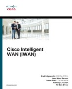
Figure 15-2 illustrates a sample network architecture that provides guest access to the Internet. Internet connectivity is provided by R41’s GigabitEthernet0/2 interface, which is attached to an Internet service provider (ISP) that is using DHCP to assign an IP address on the 100.64.41.0/24 network. The internal LAN network (10.4.4.0/24) is attached to GigabitEthernet1/0, and the guest network (192.168.41.0/24) is attached to GigabitEthernet1/1. The Layer 2 switch connects each of these cables and associates each link into the proper VLAN. In essence, VLAN 10 belongs to the default VRF (global), and VLAN 20 provides guest connectivity through the Internet FVRF. The wireless users are locally connected at the branch and not anchored to a wireless controller.
Another common method of segmenting guest and corporate user traffic is to use 802.1Q tagged subinterfaces on the router, and then the port on the switch is configured as a VLAN trunk. This reduces the number of physical interfaces that are required.
Following is the process for creating an FVRF:
Step 1. Create the front-door VRF (FVRF).
The VRF instance is created with the command vrf definition vrf-name.
Step 2. Identify the address family.
Initialize the appropriate address family for the transport network with the command address-family {ipv4 | ipv6}. The address family can be IPv4, IPv6, or both.
Step 3. Associate the FVRF to the interface.
Enter interface configuration submode and specify the interface to be associated with the VRF with the command interface interface-id. The VRF is linked to the interface with the interface parameter command vrf forwarding vrf-name.
Step 4. Configure an IP address on the interface.
Configure an IPv4 address with the command ip address {ip-address subnet-mask | dhcp} or with an IPv6 address with the command ipv6 address ipv6-address/prefix-length.
Example 15-1 provides a sample configuration for the branch LAN network and branch guest network that is hosted on R41. Notice that the alternative configuration with subinterface configuration is provided as well. The subinterface number does not determine the VLAN tag used, but the command encapsulation dot1q vlan specifies the VLAN tag that is used on the Layer 2 switch to correlate with that subinterface on R41.
Example 15-1 Branch LAN and Guest Network Configuration
R41 (Interface for Each Function)
interface GigabitEthernet1/0
description SITE-LAN
ip address 10.4.4.1 255.255.255.0
!
interface GigabitEthernet1/1
description GUEST-USERS
vrf forwarding INET01
ip address 192.168.41.1 255.255.255.0
R41 (Sub-Interface for Each Function)
interface GigabitEthernet1/0.10
encapsulation dot1q 10
description SITE-LAN
ip address 10.4.4.1 255.255.255.0
!
interface GigabitEthernet1/0.20
encapsulation dot1q 20
description GUEST-USERS
vrf forwarding INET01
ip address 192.168.41.1 255.255.255.0
Note
The topology in Figure 15-2 does not differentiate between wired and wireless clients. Larger sites can differentiate as needed and add more VLANs into the appropriate VRF context.
Dynamic Host Configuration Protocol (DHCP)
Most networks today dynamically assign IP addresses to computers and other host devices. They use a Dynamic Host Configuration Protocol (DHCP) server to allocate IP addresses from a block of IP addresses. This allows the DHCP server to track who has the IP address and for how long, and to provide any additional options.
The following steps outline the process for defining a DHCP pool that is used to dynamically assign IP addresses to guest users at the branch:
Step 1. Create a DHCP address pool.
The DHCP address pool is the fundamental building block for a DHCP server. The DHCP address pool contains basic IP addressing functions such as DNS servers, default gateways, and networks that are to be assigned. The DHCP address pool is created with the command ip dhcp pool dhcp-pool-name.
Step 2. Associate the FVRF to the address pool.
The DHCP server must know which VRF context it should listen to for DHCP request packets. Any VRF besides the default VRF must be specified with the command vrf vrf-name.
Step 3. Define the network range.
The network out of which IP addresses will be assigned is defined with the command network network [{mask | /prefix-length}].
Step 4. Specify the default router.
The devices need to know what IP to use as the default gateway. The DHCP server can define the default router with the command default-router ip-address. Typically the IP address is the IP address to the guest interface.
Step 5. Define the DNS servers.
The DNS servers are responsible for performing FQDN-to-IP-address name resolution. The command dns-server ip-address [ip-address] provides the DNS settings to the DHCP client. Alternatively, the command import all places DHCP information received from the ISP into its DHCP messages.
Another option for DNS is to provide use of free DNS server offerings such as Google DNS or OpenDNS. Future integration of OpenDNS authentication may provide additional controls via an enterprise account.
Step 6. Specify the lease duration (optional).
In essence, the DHCP server assigns (lends) the IP address to a host for a specific amount of time. The DHCP client then starts to ask the DHCP server to renew the IP address it was assigned at the 50 percent mark of the lease. The lease for a DHCP reservation is defined with the command lease {days [hours] [minutes] | lifetime}.
If the lease duration is not specified, the default is one day.
Step 7. Specify the list of IP addresses that should be excluded.
IP addresses that are known to be in use for a DHCP-enabled network segment should be excluded so that they are not assigned. The command ip dhcp excluded-address [vrf vrf-name] starting-ip-address [ending-ip-address] excludes the entered IP addresses from being assigned to a DHCP client. At a minimum, the IP address for the router should be identified.
Example 15-2 displays the DHCP server configuration for the guest network segment.
Example 15-2 DHCP Server Configuration for the Guest Network
ip dhcp excluded-address vrf INET01 192.168.41.0 192.168.41.9
!
ip dhcp pool GUEST
! Use the DNS server information provided by Service Providers DHCP server
import all
vrf INET01
network 192.168.41.0 255.255.255.0
default-router 192.168.41.1
Network Address Translation (NAT)
Network Address Translation (NAT) is a technology that rewrites packet headers as packets cross through a NAT device. NAT was created to address concerns of IP address depletion, and it provides the benefit of IP address conservation while allowing internal users to access the Internet.
NAT allows multiple devices on one network to connect to another network segment, all appearing to come from only one IP address. In the context of DIA, the guest access network segment is the internal network segment, and the Internet network is the external network segment. NAT allows the internal network to use only one external IP address to connect to the Internet. This provides additional security by effectively hiding the entire internal network behind a single service-provider-assigned address.
NAT is configured to provide the guest access network connectivity to the Internet using the DHCP address learned from the service provider. The guest access network is identified as the network assigned to the inside network for NAT.
Step 1. Define the outside interface for NAT.
Enter interface configuration submode for the guest access network with the command interface interface-id. Identify the outside interface for NAT with the command ip nat outside.
Step 2. Define the inside interface for NAT.
Enter interface configuration submode for the guest access network with the command interface interface-id. Identify the inside interface for NAT with the command ip nat inside.
Step 3. Create an ACL to define the traffic to be translated.
A standard or extended ACL can be configured to identify the traffic that should be translated. A standard ACL is used because all network traffic on the guest access network should be translated. The standard ACL is defined with the command ip access-list standard access-list-name. Within the ACL, the guest network should be identified with the command permit guest-network guest-wildcard-mask.
Step 4. Enable NAT.
NAT is enabled on the branch router with the command ip nat inside source list access-list-name interface interface-id [vrf vrf-name [match-in-vrf]] [overload] [no-payload].
The interface-id is the outside interface attached to the Internet. The vrf-name is the name of the FVRF, and the match-in-vrf keyword allows the inside and outside networks to reside in the same VRF. The overload keyword enables many-to-one addressing through port address translation. The no-payload option disables payload translation and is used because there will be no static translations or protocols.
Example 15-3 demonstrates the NAT configuration on R41 for the guest access network.
Example 15-3 R41 Guest in FVRF INET01
interface GigabitEthernet0/2
description Internet Link
vrf forwarding INET01
! The DHCP server is assigning the IP address of 100.64.41.1 to this interface
ip address dhcp
ip nat outside
! Automatically enabled when NAT is configured
ip virtual-reassembly in
!
interface GigabitEthernet1/1
description GUEST-USERS
vrf forwarding INET01
ip address 192.168.41.1 255.255.255.0
ip nat inside
! Automatically enabled when NAT is configured
ip virtual-reassembly in
!
! The following two lines are a single configuration statement
ip nat inside source list GUEST interface GigabitEthernet0/2 vrf INET01 match-in-vrf
overload no-payload
!
ip access-list standard GUEST
permit 192.168.41.0 0.0.0.255
The configuration contains ip virtual-reassembly in on the NAT-enabled interfaces which is automatically enabled to support fragmented packet reassembly as required by NAT. The feature protects the router and clients from a number of fragmentation threats.
Verification of NAT
The command show ip nat translations [vrf vrf-name] [verbose] displays the inside local (guest) IP addresses. Example 15-4 demonstrates the use of the command to see the traffic that was translated by NAT. In this example a guest has initiated a traceroute to 192.0.2.1.
Example 15-4 Verification of NAT
R41-Spoke# show ip nat translations vrf INET01
Pro Inside global Inside local Outside local Outside global
udp 100.64.41.1:49157 192.168.41.10:49157 192.0.2.1:33437 192.0.2.1:33437
udp 100.64.41.1:49158 192.168.41.10:49158 192.0.2.1:33438 192.0.2.1:33438
udp 100.64.41.1:49159 192.168.41.10:49159 192.0.2.1:33439 192.0.2.1:33439
udp 100.64.41.1:49160 192.168.41.10:49160 192.0.2.1:33440 192.0.2.1:33440
udp 100.64.41.1:49161 192.168.41.10:49161 192.0.2.1:33441 192.0.2.1:33441
udp 100.64.41.1:49162 192.168.41.10:49162 192.0.2.1:33442 192.0.2.1:33442
udp 100.64.41.1:49163 192.168.41.10:49163 192.0.2.1:33443 192.0.2.1:33443
udp 100.64.41.1:49164 192.168.41.10:49164 192.0.2.1:33444 192.0.2.1:33444
R41-Spoke# show ip nat translations verbose
! Output omitted for brevity
Pro Inside global Inside local Outside local Outside global
udp 100.64.41.1:49157 192.168.41.10:49157 192.0.2.1:33437 192.0.2.1:33437
create 00:00:58, use 00:00:58 timeout:300000, left 00:04:01, Map-Id(In): 1,
flags:
extended, no-payload, match-in-vrf, use_count: 0, VRF : INET01, entry-id: 1,
lc_entries: 0
Zone-Based Firewall (ZBFW) Guest Access
A stateful firewall secures the network so that only approved network traffic is returned to the client device. The branch routers use Cisco ZBFW for the guest access network to provide stateful firewall support because specific types of traffic are allowed to guest users.
Some organizations provide the guest access network with unfettered access to the Internet, but other organizations may provide connectivity to only web-based applications.
The following steps explain how to configure access for only web-based applications on the guest access network. The configuration provides DNS connectivity for domain-name-to-IP-address resolution to find destinations.
Step 1. Define the security zones.
Zones are configured using the command zone security zone-name. One zone needs to be created for the guest access network, and one for the outside interface.
Step 2. Define the inspection class map.
The class map for inspection defines a method for classification of traffic. The class map is configured using the command class-map type inspect [match-all | match-any] class-name. The match-all keyword requires that network traffic match all the conditions listed to qualify (Boolean AND), whereas the match-any keyword requires that network traffic match only one of the conditions listed to qualify (Boolean OR). If neither keyword is specified, the match-all function is selected.
Step 3. Define the inspection policy map.
The inspection policy map applies firewall policy actions to the class maps defined in the policy map. The policy map is then associated to a zone pair.
The inspection policy map is defined with the command policy-map type inspect policy-name. After the policy map is defined, the various class maps are defined with the command class type inspect class-name. Under the class map, the firewall action is defined with the following commands:
![]() drop [log]: This is the default action which silently discards packets that match the class map. The log keyword adds syslog information that includes source and destination information (IP address, port, and protocol).
drop [log]: This is the default action which silently discards packets that match the class map. The log keyword adds syslog information that includes source and destination information (IP address, port, and protocol).
![]() pass [log]: This action makes the router forward packets from the source zone to the destination zone. Packets are forwarded only in one direction. A policy must be applied for traffic to be forwarded in the opposite direction. The pass action is useful for protocols such as IPsec ESP and other inherently secure protocols with predictable behavior. The optional log keyword adds syslog information that includes the source and destination information.
pass [log]: This action makes the router forward packets from the source zone to the destination zone. Packets are forwarded only in one direction. A policy must be applied for traffic to be forwarded in the opposite direction. The pass action is useful for protocols such as IPsec ESP and other inherently secure protocols with predictable behavior. The optional log keyword adds syslog information that includes the source and destination information.
![]() inspect: The inspect action offers state-based traffic control. The router maintains connection/session information and permits return traffic from the destination zone without the need to specify it in a second policy.
inspect: The inspect action offers state-based traffic control. The router maintains connection/session information and permits return traffic from the destination zone without the need to specify it in a second policy.
The inspection policy map has an implicit class default that uses a default drop action. This provides the same implicit “deny all” that is found in an ACL. Adding it to the configuration may simplify troubleshooting for junior network engineers
Step 4. Define the zone pairs.
A policy map is now applied to a traffic flow source to a destination configured as zone-pair security zone-pair-name source source-zone-name destination destination-zone-name. The inspection policy map is then applied to the zone pair with the command service-policy type inspect policy-name. Traffic will be statefully inspected between the source and destination, with return traffic allowed.
Step 5. Apply the security zones to the appropriate interfaces.
An interface is assigned to the appropriate zone by entering interface configuration submode with the command interface interface-id and associating the interface to the correct zone with the command zone-member security zone-name as defined in Step 1.
Example 15-5 is the deployed configuration for our guest users. Guest users are allowed DNS access to find a destination address and access to HTTP and HTTPS websites and applications.
Example 15-5 R41 Guest in FVRF INET01 Zone-Based Firewall Configuration
zone security OUTSIDE
description OUTSIDE Zone used for Internet Interface
zone security GUEST
description GUEST Zone used for limited Guest Internet Access
!
ip access-list extended ACL-DENY-ANY-IP
deny ip any any
!
class-map type inspect match-any CLASS-GUEST-TO-OUTSIDE
match protocol dns
match protocol http
match protocol https
match access-group name ACL-DENY-ANY-IP
!
policy-map type inspect POLICY-GUEST-TO-OUTSIDE
class type inspect CLASS-GUEST-TO-OUTSIDE
inspect
class class-default
drop
!
zone-pair security GUEST-TO-OUTSIDE source GUEST destination OUTSIDE
service-policy type inspect POLICY-GUEST-TO-OUTSIDE
!
interface GigabitEthernet0/2
description Internet Link
vrf forwarding INET01
! The DHCP server is assigning the IP address of 100.64.41.1 to this interface
ip address dhcp
zone-member security OUTSIDE
!
interface GigabitEthernet1/1
description GUEST-USERS
vrf forwarding INET01
ip address 192.168.41.1 255.255.255.0
zone-member security GUEST
Example 15-6 provides the ZBFW configuration from Chapter 5, “Securing DMVPN Tunnels and Routers,” that allows for DMVPN tunnel establishment and basic connectivity tests. This configuration is provided for reference so that readers can see the complete ZBFW configuration in one place.
Example 15-6 Reference ZBFW Configuration for DMVPN, Ping, and Traceroute
zone security OUTSIDE
description OUTSIDE Zone used for Internet Interface
!
ip access-list extended ACL-DHCP-IN
permit udp any eq bootps any eq bootpc
ip access-list extended ACL-DHCP-OUT
permit udp any eq bootpc any eq bootps
ip access-list extended ACL-ESP
permit esp any any
ip access-list extended ACL-GRE
permit gre any any
ip access-list extended ACL-ICMP
permit icmp any any
ip access-list extended ACL-IPSEC
permit udp any any eq non500-isakmp
permit udp any any eq isakmp
ip access-list extended ACL-PING-AND-TRACEROUTE
permit icmp any any echo
permit icmp any any echo-reply
permit icmp any any ttl-exceeded
permit icmp any any port-unreachable
permit udp any any range 33434 33463 ttl eq 1
!
class-map type inspect match-any CLASS-OUTSIDE-TO-SELF-INSPECT
match access-group name ACL-IPSEC
match access-group name ACL-PING-AND-TRACEROUTE
class-map type inspect match-any CLASS-OUTSIDE-TO-SELF-PASS
match access-group name ACL-ESP
match access-group name ACL-DHCP-IN
match access-group name ACL-GRE
class-map type inspect match-any CLASS-SELF-TO-OUTSIDE-INSPECT
match access-group name ACL-IPSEC
match access-group name ACL-ICMP
class-map type inspect match-any CLASS-SELF-TO-OUTSIDE-PASS
match access-group name ACL-ESP
match access-group name ACL-DHCP-OUT
!
policy-map type inspect POLICY-OUTSIDE-TO-SELF
class type inspect CLASS-OUTSIDE-TO-SELF-INSPECT
inspect
class type inspect CLASS-OUTSIDE-TO-SELF-PASS
pass
class class-default
drop
!
policy-map type inspect POLICY-SELF-TO-OUTSIDE
class type inspect CLASS-SELF-TO-OUTSIDE-INSPECT
inspect
class type inspect CLASS-SELF-TO-OUTSIDE-PASS
pass
class class-default
drop log
!
zone-pair security SELF-TO-OUTSIDE source self destination OUTSIDE
service-policy type inspect POLICY-SELF-TO-OUTSIDE
!
zone-pair security OUTSIDE-TO-SELF source OUTSIDE destination self
service-policy type inspect POLICY-OUTSIDE-TO-SELF
Verification of ZBFW for Guest Access
The verification of guest access can be seen on the ZBFW with the command show policy-map type inspect zone-pair zone-pair-name [sessions] which is demonstrated in Example 15-7. In the example, packets have been passed by the ZBFW for DNS, HTTP, and HTTPS and other traffic has been dropped.
Example 15-7 Verification of ZBFW for Guest Access
R41-Spoke# show policy-map type inspect zone-pair GUEST-TO-OUTSIDE sessions
policy exists on zp GUEST-TO-OUTSIDE
Zone-pair: GUEST-TO-OUTSIDE
Service-policy inspect : POLICY-GUEST-TO-OUTSIDE
Class-map: CLASS-GUEST-TO-OUTSIDE (match-any)
Match: protocol dns
123 packets, 9630 bytes
5 minute rate 1000 bps
Match: protocol http
2030 packets, 288079 bytes
5 minute rate 5000 bps
Match: protocol https
172 packets, 15562 bytes
5 minute rate 1000 bps
Inspect
Class-map: class-default (match-any)
Match: any
Drop
84581 packets, 325696 bytes
Guest Access Quality of Service (QoS)
Regulating the amount of WAN bandwidth consumed by the guest network should be considered when developing DIA designs. The branch site location must have sufficient bandwidth for critical business operations (internal user applications) while providing the delta to the guest network. A common technique is to place all traffic received from the guest network in a Scavenger QoS class on the WAN egress interface. The Scavenger class is meant for applications of a lower priority than best effort; in essence any bandwidth not consumed by corporate users is available for the guest network.
The egress QoS policy may need adjustment to allow a Scavenger class to support guests under congestion, providing the guest users with appropriate performance to fit the business model. Some public-facing organizations (such as retail and hospitals) need to provide guest Internet access as part of their business model and need to guarantee that guest traffic is treated appropriately in comparison to internal users’ application traffic. Based on the business model for guest user access, a dedicated queuing structure can be built to keep guest traffic separate from other traffic.
The following steps create a QoS policy map to mark all guest network traffic as part of the Scavenger class.
Step 1. Configure QoS for control of guest user egress traffic.
Enter policy map submode using the command policy-map policy-name.
Step 2. Use a single queue for all guest user traffic.
Enter default class submode using the command class class-default.
Step 3. Assign all guest user traffic to a specific egress queue.
Mark traffic to the appropriate queue using the command set dscp dscp-value.
Step 4. Apply the QoS policy to the guest access interface.
Enter interface configuration submode for the guest access network with the command interface interface-id. Apply the QoS policy with the command service-policy input policy-name.
In Example 15-8, all guest user traffic is assigned the DSCP value of CS1 by applying an input policy to the guest network interface. DSCP CS1 is a typical Scavenger class setting, where the traffic is considered less than best effort, based on other applications having preference for limited bandwidth.
Example 15-8 R41 Guest in FVRF INET01 Quality of Service WAN Egress
R41
policy-map POLICY-GUEST-TO-INTERNET
description remark all GUEST Traffic Scavenger
class class-default
set dscp cs1
!
interface GigabitEthernet1/1
description GUEST-USERS
vrf forwarding INET01
ip address 192.168.41.1 255.255.255.0
service-policy input POLICY-GUEST-TO-INTERNET
This QoS marking policy addresses traffic flowing from the branch to the Internet, but the return traffic must be considered. A guest user could download a large file that congests inbound bandwidth from the Internet, affecting corporate users. It is recommended that a QoS traffic-shaping policy be deployed to rate-limit the amount of traffic consumed by guest users.
Because the guest network connects via a single inside interface, the use of an egress shaper toward the guest network is appropriate and is called Remote Ingress Shaping. This shaper is applied after the router has already received the traffic, so the router needs to limit network traffic below the rate that is allowed to the guest network. A good rule of thumb is to set the shaping rate to 95 percent of the offered bandwidth so that TCP windowing controls the maximum rate allowed. The use of fair queuing is configured to give multiple users a fair share of the bandwidth. Increasing the queue depth smooths out any drops but introduces the possibility of increasing delay.
The following steps create a Remote Ingress Shaper for the guest network traffic.
Step 1. Define the guest access ingress QoS policy.
Enter policy map submode using the command policy-map policy-name.
Step 2. Define a single queue for all guest traffic.
Enter default class submode using the command class class-default.
Step 3. Rate-limit all guest access traffic.
Guest access network traffic is shaped down to an acceptable bandwidth rate with the command shape average kbps.
Step 4. Enable fair queuing.
The fair queue is configured with the command fair-queue.
Step 5. Apply the QoS policy to the guest access interface.
Enter interface configuration submode for the guest access network with the command interface interface-id. Apply the QoS policy with the command service-policy output policy-name.
Example 15-9 demonstrates a sample configuration for assigning a QoS policy for traffic returning from the Internet to the guest access network.
Example 15-9 R41 Guest in FVRF INET01 Quality of Service WAN Ingress
policy-map INTERNET-TO-GUEST
description shape all GUEST Traffic Allowed
class class-default
! 95% of 2Mbps
shape average 1900000
fair-queue
!
interface GigabitEthernet1/1
description GUEST-USERS
vrf forwarding INET01
ip address 192.168.41.1 255.255.255.0
service-policy output INTERNET-TO-GUEST
Now that the guest network is defined and operational, some changes to Per-Tunnel QoS should be reviewed to provide the needed headroom to prevent internal traffic from competing with the guest network. In this section, 2 Mbps was allocated for the guest network, so to protect internal traffic a reduction of the Per-Tunnel QoS shaper by 2 Mbps is required.
Guest Access Web-Based Acceptable Use Policy
Most organizations require that guest users accept an “acceptable use policy” via a web page. Depending on the level of security, users may be required to provide their consent, or authenticate with some form of password. This feature can be enabled by using the router’s integrated consent feature with minimal configuration. The following sections cover both techniques.
Guest Network Consent
The consent feature allows the specification of an appropriate login banner and login HTML page specifying the required acceptable use policy. This feature requires that the HTTP server be enabled on the router. A standard numbered ACL (such as 99) denies all traffic to the HTTP server, so that the authentication proxy can establish an HTTP session for the specific client redirection.
The authentication proxy operates by defining an admission name and correlating an ACL for any traffic that requires consent. The ACL denies specific protocols that should be allowed such as DNS and DHCP. All other protocols are permitted and are then redirected and captured. The authentication proxy is then associated to an interface where it should listen for traffic that matches the ACL.
The authentication proxy feature requires an HTML file with the organization’s acceptable use policy. Example 15-10 provides a reference file, consent.html, that will be copied onto the router.
Example 15-10 Guest Access Consent File (consent.html)
<html>
<head>
<title>Guest Network Access</title>
</head>
<body>
<center><h1>Guest Network Access</h1></center>
<p>By agreeing to this page, you take full responsibility for your actions.
<p>You agree that your data will be logged, documented, and handed over to
authorities should it be requested.
<br>
</body>
</html>
The following steps configure the guest network consent function on a router:
Step 1. Copy the consent banner to the router.
An HTML file is created with acceptable company verbiage. This file is copied onto the router with the command copy {ftp | http | https | tftp | scp}://html-file.html {bootflash | disk0 | flash | harddisk}://html-file.html.
Step 2. Identify the consent banner file.
The consent banner file is configured using the command ip admission consent-banner file {bootflash | disk0 | flash | harddisk}://html-file.html.
Step 3. Define a simple text consent banner (optional).
If only a simple banner is required, a simple text banner can be created with the command ip admission consent-banner text delimiting-character consent-banner-text delimiting-character.
Step 4. Define an ACL for interesting traffic.
Configure an ACL for traffic that will trigger the consent page. The consent ACL uses a deny statement for allowed traffic and a permit to capture traffic for IP admission to use.
Step 5. Configure an admission name.
An admission policy is created for placement on the ingress interface, using the command ip admission name admission-name consent list access-list-name.
Step 6. Enable the HTTP server.
Enable the HTTP server capability on the router with the command ip http server. A dedicated HTTP process is triggered for the IP admission process.
Configure a standard numbered ACL that restricts all guest network traffic to the server with the command access-list 99 deny any. Apply this access list to the HTTP process using the command ip http server access-class 99.
Step 7. Apply the admission name to the ingress guest interface.
Enter interface submode using the command interface interface-id and apply the admission name using the command ip admission admission-name.
In Example 15-11, the ACL-GUEST is configured so that DNS and DHCP are denied, which then allows a client to receive an IP address, resolve an IP from an FQDN, and then establish an initial session to trigger the acceptable use policy web page for acceptance.
Example 15-11 R41 Guest Consent Acceptance
ip admission consent-banner file flash:consent.html
ip admission consent-banner text ^C Guest Network Consent ^C
ip admission watch-list enable
ip admission max-login-attempts 3
ip admission max-nodata-conns 20
ip admission auth-proxy-audit
ip admission name GUEST consent inactivity-time 60 list ACL-GUEST
!
interface GigabitEthernet1/1
description GUEST-USERS
vrf forwarding INET01
ip address 192.168.41.1 255.255.255.0
ip admission GUEST
!
ip http server
ip http access-class 99
!
ip access-list extended ACL-GUEST
deny udp any any eq domain
deny udp any eq bootpc any eq bootps
permit ip any any
!
access-list 99 deny any
end
Note
The command ip admission auth-proxy-audit logs new connections with the initiating IP address when the connection is first established. This information can be correlated to the DHCP lease logs for granular reporting.
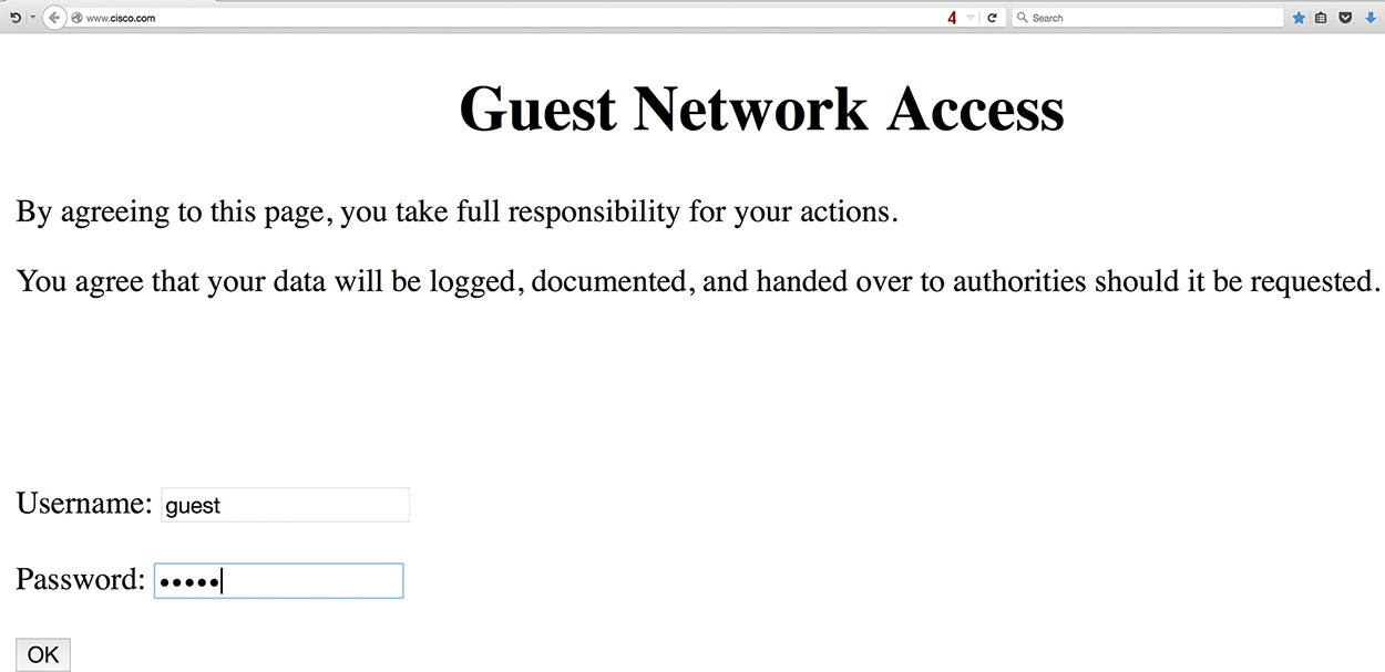
In Figure 15-3, the web browser has been opened, and the initial web request to the browser’s home page (www.cisco.com) has been redirected to the router’s consent page. The guest user will choose “Accept” or “Don’t Accept” for the agreement as specified in the ip admission consent-banner file file-name command. After the agreement has been accepted, by default the browser displays the initially requested web page.

Example 15-12 demonstrates the syslog information that is provided when ip admission auth-proxy-audit is enabled on the router.
Example 15-12 IP Admission Logs
%AP-6-AUTH_PROXY_AUDIT_START: initiator (192.168.41.10) start
%AP-6-AUTH_PROXY_AUDIT_STOP: initiator (192.168.41.10) send 0 packets 0 bytes;
duration time 00:18:10
A list of recent guest clients that have accepted the consent page can be seen with the command show ip admission cache as shown in Example 15-13.
Example 15-13 R41 Verification of Consenting Clients
R41-Spoke# show ip admission cache
Authentication Proxy Cache
Client Name N/A, Client IP 192.168.41.10, Port 54727, timeout 60,
Time Remaining 60, state ESTAB
Note
When configuring the various ip admission commands, IOS automatically configures the equivalent legacy ip auth-proxy commands. In essence, it appears as if the configuration is duplicated, but the removal of either the ip admission or the ip auth-proxy command removes both instances.
Guest Authentication
Some organizations may feel that a consent page is insecure because anyone sitting in range of the wireless network can gain access by accepting the terms on the consent page. An additional level of security can be added by using a pre-shared WiFi Protected Access (WPA) password that can be stored on devices. Another method of securing the wireless network is to require users to authenticate via a web authentication portal. The router can use a radius, TACACS, or Cisco Identity Services Engine’s (ISE) guest portal.
The same configuration structure as consent is used for guest authentication. The same consent.html file is used, and users are authenticated locally for this section. Users are required to provide a valid username and password to connect to the Internet. The process for configuring authentication is as follows:
Step 1. Create local user accounts.
The authentication mechanism requires the use of the authentication, authorization, and accounting (AAA) access model. An administrative user account (privilege level 15) should be created with the command username username [privilege privilege-level] [{password | secret} password].
Our example uses a local shared user guest-account account that will be used for authenticating into the portal. This user should be assigned a system-level privilege of 0.
Step 2. Initialize the AAA model.
Initialize the AAA model with the command aaa new-model.
Step 3. Create a new AAA authentication mechanism.
The AAA authentication mechanism identifies how a specific router’s access method verifies the validity of the account. This does not tell the router the type of access that the user is allowed.
The command is aaa authentication login {default | aaa-list-name} [method1] [method2] [method3] . . . . A wide variety of methods are available, but the short list is:
![]() enable: The enable password.
enable: The enable password.
![]() local: Local user database is used.
local: Local user database is used.
![]() none: No authentication.
none: No authentication.
![]() group radius: Authenticate off a defined radius server.
group radius: Authenticate off a defined radius server.
![]() group tacacs: Authenticate off a defined TACACS server.
group tacacs: Authenticate off a defined TACACS server.
This example uses local authentication.
Step 4. Create a new AAA authorization for auth-proxy.
The AAA authorization mechanism defines the level of access that a user is allowed. The command is aaa authorization auth-proxy default [group server-group-name] [local]. Either a group or local method must be configured. This example uses local.
Step 5. Create an AAA attribute list for the guest user account.
The user account has a default privilege level of 0 on the router but requires elevated privileges for the auth-proxy protocol. An AAA attribute list is created with the command aaa attribute list aaa-attribute-list-name.
Then the privilege level 15 is associated to the auth-proxy protocol with the command attribute type priv-lvl 15 service auth-proxy protocol ip.
Step 6. Associate the auth-proxy AAA attribute to the guest user account.
Now the AAA attribute list is associated with the local user account with the command username username aaa attribute list aaa-attribute-list-name.
Step 7. Copy the authentication banner to the router.
An HTML file is created with acceptable company verbiage. This file is copied onto the router with the command copy {ftp | http | https | tftp | scp}://html-file.html {bootflash | disk0 | flash | harddisk}://html-file.html.
Step 8. Identify the authentication banner file.
The consent banner file is configured using the command ip admission auth-proxy-banner file {bootflash | disk0 | flash | harddisk}://html-file.html.
Step 9. Configure a simple text authentication banner (optional).
If only a simple authentication banner is required, it can be made with the command ip admission auth-proxy-banner text delimiting-character consent-banner-text delimiting-character.
Step 10. Define an ACL for interesting traffic.
Configure an ACL for traffic that will trigger the authentication page. The authentication ACL uses a deny statement for allowed traffic and a permit to capture traffic for IP admission to authenticate.
Step 11. Configure an admission policy.
An admission policy is created for placement on the ingress interface using the command ip admission name admission-name proxy http list access-list-name.
Step 12. Enable the HTTP server.
Enable the HTTP server capability on the router with the command ip http server. A dedicated HTTP process is triggered for the IP admission process.
Configure a standard numbered ACL that restricts all guest network traffic to the server with the command access-list 99 deny any. Apply this access list to the HTTP process using the command ip http server access-class 99.
Step 13. Apply the admission policy to the ingress guest interface.
Enter interface submode using the command interface interface-id and apply the admission policy using the command ip admission admission-name.
Example 15-14 demonstrates the configuration for guest authentication. Notice that the ip admission consent commands have been replaced with ip admission auth-proxy commands. Also, the keywords proxy http have been added to the IP admission name command.
Example 15-14 R41 Guest Authentication
username guest-account privilege 0 secret PASSWORD123
!
aaa new-model
aaa authentication login AAA-AUTH-PROXY local
aaa authorization auth-proxy default local
!
username guest-account aaa attribute list GUEST
aaa attribute list GUEST
attribute type priv-lvl 15 service auth-proxy protocol ip
!
ip admission auth-proxy-banner file flash:consent.html
ip admission auth-proxy-banner http * Guest Network Authentication *
ip admission watch-list enable
ip admission watch-list expiry-time 5
ip admission max-nodata-conns 1000
ip admission init-state-timer 15
ip admission auth-proxy-audit
ip admission name GUEST-AUTH proxy http inactivity-time 60 list ACL-GUEST
!
interface GigabitEthernet1/1
description GUEST-USERS
vrf forwarding INET01
ip address 192.168.41.1 255.255.255.0
ip admission GUEST-AUTH
!
ip http server
ip http access-class 99
!
ip access-list extended ACL-GUEST
deny udp any any eq domain
deny udp any eq bootpc any eq bootps
permit ip any any
!
access-list 99 deny any
end
Note
The same HTML file can be used for consent or authentication. IP admission provides either the radio buttons for acceptance or the username and password prompts for authentication.
In Figure 15-4, the web browser has been opened, and the initial web request to the browser’s home page has been redirected to the router’s auth-proxy-banner page. Here the user is prompted for username and password. Attempting to authenticate implies the acceptance of the specified agreement from the ip admission auth-proxy-banner file. After the user is authenticated, by default the browser displays the initially requested web page.
Note
In Figure 15-4, local user authentication was used, but it is possible to use most AAA methods available by changing the aaa authorization auth-proxy default to a different method.
Now that the basic web-based authentication has been demonstrated, additional customization can be done by providing a unique file for login, success, failure, or expiration. The commands for additional customization are ip admission proxy http {login | success | failure | expired} page file url. It is even possible to send an HTTP redirect to a different website URL with the command ip admission proxy http success redirect url. Example 15-15 demonstrates the configuration.
Example 15-15 Guest Authentication Customized Web Pages
ip admission proxy http login page file bootflash:login.htm
ip admission proxy http success page file bootflash:success.htm
ip admission proxy http failure page file bootflash:fail.htm
ip admission proxy http expired page file bootflash:expired.htm
ip admission proxy http success redirect www.company.com
Note
The Authentication Proxy Configuration Guide listed at the end of this chapter includes more information on how to customize the web proxy authentication web pages.
To verify authenticated clients, just as with consent, the command show ip admission cache displays the users that are connected. The command show ip admission watch-list displays the IP addresses of those systems that are on the network but have not authenticated. Example 15-16 demonstrates the use of both commands. Only the 192.168.41.10 is present on the network and has authenticated with the router.
Example 15-16 R41 Verification of Authenticating Clients
R41-Spoke# show ip admission cache
Authentication Proxy Cache
Client Name N/A, Client IP 192.168.41.10, Port 54727, timeout 60, Time
Remaining 60, state ESTAB
R41-Spoke# show ip admission watch-list
Authentication Proxy Watch-list is enabled
Watch-list expiry timeout is 5 minutes
No entries in the watch-list
If the design requires the ability to log user access and limit the amount of time the user can use the free service, an external system is necessary. This is where the Cisco ISE is required. Many options are available via ISE to support guest users with both self-registration and sponsored guest access. ISE offers web-based authentication with acceptable use policy, duration limits, one-time authentication, and logging. A key design component requires that the ISE subnet be reachable by both internal and guest users. More information on the use of ISE with guest access can be found in Cisco Validated Design, IWAN Security for Remote Site Direct Internet Access and Guest Wireless.
Internal User Access
Granting direct access to the Internet for internal users can increase productivity, offload bandwidth-consuming applications from the WAN, and decrease latency to critical cloud-based applications. In the centralized Internet model, all traffic to and from the Internet traverses a rather complex security architecture and minimizes the number of touchpoints to the Internet. As the application footprint has changed, the ability to maintain a centralized Internet model meeting bandwidth and low-latency requirements has become an issue. Moving to a distributed model is an easy choice for those working with the applications and the departments funding the circuits, but the security team needs to validate that the solution meets their requirements.
As with guest Internet access, the simplest solution for providing Internet access to internal branch users is by using a static route to the Internet SP. The Internet’s interface is placed in a dedicated FVRF for segmentation, interface selection for transport independence, and so forth. It is possible to connect the INET01’s routing table with the global routing table.
In this design, the FVRF’s default route is used to establish DMVPN tunnels, and the global table’s fully specified static route provides direct access to the Internet. The design includes the monitoring of the local Internet connection, and in the event of failure traffic can be routed to the Internet (via the DMVPN tunnel) in a centralized Internet access model.
Figure 15-5 illustrates all these concepts from R41’s perspective. Notice that R41 has multiple default routes in the routing table but installs the static route into the RIB as long as the tracking provides successful verification to the Internet.

Several steps are involved in providing internal users with direct Internet access. The configuration looks similar to a typical split-tunneled VPN deployment that includes
![]() A default route via the Internet-facing interface
A default route via the Internet-facing interface
![]() NAT to use the provided service provider routable address
NAT to use the provided service provider routable address
![]() ZBFW to statefully allow only requested responses and denial of unrequested traffic
ZBFW to statefully allow only requested responses and denial of unrequested traffic
![]() The return traffic from the Internet remains in the front-door VRF and requires restoration to the global routing table. This is accomplished using policy-based routing (PBR) to restore traffic after processing by NAT and ZBFW to the global routing table.
The return traffic from the Internet remains in the front-door VRF and requires restoration to the global routing table. This is accomplished using policy-based routing (PBR) to restore traffic after processing by NAT and ZBFW to the global routing table.
Note
Because the static route installs over the default route advertised from the DMVPN hub routers, more explicit enterprise network prefixes must be advertised from the DMVPN hub routers.
Fully Specified Static Default Route
The first step for internal direct Internet access is to create a route in the global routing table that allows connectivity to the Internet FVRF physical interface, with an administrative distance that is preferred over a routing protocol. (Remember, the default route is advertised from the DMVPN hub routers too.) The default administrative distance for static routes is 1, which prevents us from installing an additional preferred route in the future, so our example uses an administrative distance of 10. The outbound interface must be specified for two essential reasons:
![]() If the interface loses link protocol (connectivity) to the Internet, the static route is removed from the routing table.
If the interface loses link protocol (connectivity) to the Internet, the static route is removed from the routing table.
![]() It must be included to provide outbound connectivity from the global VRF to the FVRF.
It must be included to provide outbound connectivity from the global VRF to the FVRF.
The command ip route 0.0.0.0 0.0.0.0 internet-interface {next-hop-ip | dhcp} [administrative-distance] configures the appropriate static route. Example 15-17 provides the sample configuration and verification of the default route.
Example 15-17 R41 Internal Internet Access Default Route Configuration
R41
ip route 0.0.0.0 0.0.0.0 GigabitEthernet0/2 100.64.41.2 10
R41-Spoke# show ip route 0.0.0.0
Routing entry for 0.0.0.0/0, supernet
Known via "static", distance 10, metric 0, candidate default path
Routing Descriptor Blocks:
* 100.64.41.2, via GigabitEthernet0/2
Route metric is 0, traffic share count is 1
Verification of Internet Connectivity
The installed route points to a dedicated interface, and the static default route is disabled when the interface goes down. A majority of broadband Internet circuits are provided via cable, DSL, or a fiber-optic service that is not Ethernet, requiring the use of an external modem that does not provide link propagation. This leaves the router’s Ethernet interface up when the Internet service is down or degraded.
The IWAN architecture is built with reliable hub sites that can test connectivity by tracking the Internet DMVPN tunnel interface state, but the failure detection time is fairly long because detection time is based on NHRP timers. The same issue occurs with tracking routing protocol neighbors because of the increased timers. Detection time is enhanced with the use of Cisco IP SLA capability that is built into IOS. IP SLA can monitor DNS resolution, HTTP requests, or an ICMP echo to a reliable destination
Tracking one remote endpoint is not sufficient because of maintenance cycles. Is it sufficient for a reachability test to connect to only one specific website or IP address? Enhanced object tracking (EOT) provides intelligence by querying the state of multiple items on the Internet. Combined with IP SLA capability, it enhances the ability to determine if the Internet circuit is functioning properly. Sending a ping to the DMVPN hub routers at an acceptable rate provides a reliable measure for a source that is controlled by your organization.
Note
Some people might ping the next-hop IP address of the ISP, but if the router is on DHCP, it may be hard to determine. Other people might ping Google’s DNS servers, but what happens if they apply a security policy to deny ICMP packets? The DMVPN hub servers are controlled by your organization, and no outsiders can change the configuration or security policies, which can cause unexpected issues.
Combining these monitoring capabilities to increase the reliability of the tracked objects is of utmost importance. This is where using a tracked object with thresholds is required. EOT supports the tracking of other tracked objects (nested) so that multiple objects can be tracked and a percentage or weight value assigned for each state. The EOT tracking is then added to the static default route, which removes the route if the tracked status is down.
In a simple example, the status of the Internet can be determined by tracking
![]() The Internet DMVPN tunnel interface
The Internet DMVPN tunnel interface
![]() Routing over the DMVPN tunnel interface
Routing over the DMVPN tunnel interface
![]() Availability of DNS query to both Google DNS servers for www.google.com
Availability of DNS query to both Google DNS servers for www.google.com
When 51 percent or less of IP SLAs are available, the router should identify the state as down, indicating that DIA connectivity is not available. But if 74 percent of the IP SLAs are available, then the state is up and DIA connectivity is available. This logic requires that three of the four tests be available for DIA connectivity to be viable. Having only two of four available—50 percent—is lower than the configured 51 percent so the DIA path is considered down.
Another option is to establish that one tracked item is more important than another tracked object. Multiple tracked objects are then nested into a single tracked object. The child tracked objects can be weighted to give one precedence over another. This logic is used in Example 15-11. It is also possible to use weight as shown in Example 15-18.
The following steps define how Internet connectivity can be monitored on the branch routers.
Step 1. Configure an IP SLA.
Cisco IOS IP SLAs generate traffic in a continuous, reliable, and predictable manner to measure network performance. The network traffic includes data about response time, one-way latency, jitter (inter-packet delay variance), packet loss, network resource availability, and server response time.
Every test is provided with its own instance. The IP SLA instance is created with the command ip sla ip-sla-number.
Step 2. Define the type of IP SLA.
IP SLA provides multiple functions, but in this book IP SLA is used for a basic IP connectivity test via ICMP and DNS query.
ICMP IP SLAs are configured with the command icmp-echo {destination-ip-address | destination-hostname} [source-ip ip-address | source-interface interface-id]. Specifying a source-ip or source-interface is optional.
DNS query IP SLAs are configured with the command dns {destination-ip-address | destination-hostname} [source-ip ip-address | source-interface interface-id]. Specifying a source-ip or source-interface is optional.
Step 3. Define the type of IP SLA.
If the IP SLA resides in a VRF, the VRF must be specified with the command vrf vrf-name.
Step 4. Define the frequency of the IP SLA test.
The frequency of the IP SLA test needs to be defined with the command frequency seconds. The book’s example uses a value of 15.
Step 5. Define the upper threshold value of the IP SLA test.
The upper threshold value for calculating network-monitoring statistics created by an IP SLA is defined with the command threshold milliseconds.
Step 6. Define the timeout of the IP SLA test.
The amount of time that an IP SLA waits in response for a packet is defined with the command timeout milliseconds. The book’s example uses a value of 3000.
Step 7. Schedule the IP SLA to run.
The IP SLA needs to have a start and stop time identified. The command ip sla schedule ip-sla-number life forever start-time now continuously runs the IP SLA.
Step 8. Create child tracked objects.
Every one of the individual IP SLAs needs to be configured as a child tracked object with the command track track-number ip sla ip-sla-number.
The state of a DMVPN tunnel can be tracked with the command track track-number interface interface-id line-protocol. DMVPN tunnel health monitoring must be enabled with the interface parameter command if-state nhrp.
Step 9. Create a track list to monitor all child objects.
The command track track-number list threshold {percentage | weight} creates the master tracking entity. Underneath the master track list, the previously tracked objects are added with the command object track-number [weight weight].
If all objects have an equal percentage or weight, percentage can be used. If some objects are more important than others, use of weight is recommended.
Step 10. Define a threshold for when a track list is up or down.
A threshold needs to be defined for when a track list is up or down. The command threshold weight [up up-value] [down down-value]. At least one of the up and down keywords must be specified with this command.
Step 11. Update the static route to reflect the tracked route.
The fully specified static route can now be included to include tracking with the command ip route 0.0.0.0 0.0.0.0 internet-interface {next-hop-ip | dhcp} [administrative-distance] track track-number.
Note
It is recommended to match the track number to the IP SLA number to simplify verification of threshold-based tracked objects.
Example 15-18 provides a sample configuration for weighted tracking of the Internet. Four IP SLAs are created. Two are ICMP echo for the Internet DMVPN hub transport IP addresses, and the other two IP SLAs are DNS queries for root DNS servers. There are multiple root DNS servers with the same FQDN. The master tracked list combines the four IP SLA entries and the Internet DMVPN tunnel status.
Example 15-18 R41 Internet Monitoring
! Internet Tunnel Interface Hub at Data Center 1
ip sla 201
icmp-echo 100.64.12.1 source-interface GigabitEthernet0/2
vrf INET01
threshold 1000
frequency 15
ip sla schedule 201 life forever start-time now
! Internet Tunnel Interface Hub at Data Center 2
ip sla 202
icmp-echo 100.64.22.1 source-interface GigabitEthernet0/2
vrf INET01
threshold 1000
frequency 15
ip sla schedule 202 life forever start-time now
! D DNS Root Server which is Anycast
ip sla 211
dns d.root-servers.net name-server 199.7.91.13
vrf INET01
threshold 1000
timeout 3000
frequency 15
ip sla schedule 211 life forever start-time now
! F DNS Root Server which is Anycast
ip sla 212
dns f.root-servers.net name-server 192.5.5.241
vrf INET01
threshold 1000
timeout 3000
frequency 15
ip sla schedule 212 life forever start-time now
!
! Internet Tunnel Interface State
! "if-state nhrp" configuration required
track 20 interface Tunnel200 line-protocol
!
track 21 ip sla 201 reachability
track 22 ip sla 202 reachability
track 23 ip sla 211 reachability
track 24 ip sla 212 reachability
!
track 100 list threshold weight
! The default weight 10
object 20
object 21
object 22
! The DNS request is twice as important
object 23 weight 20
object 24 weight 20
threshold weight down 21 up 40
! Delay coming up for 30 seconds in case we are having transient issues
delay up 30
!
ip route 0.0.0.0 0.0.0.0 GigabitEthernet0/2 100.64.41.2 10 track 100
One of the problems associated with using a DHCP learned next hop is that direct tracking is not an option as shown in Example 15-19. The solution is to install a static host route in the global table pointed to an IP address that does not require connectivity, because this host route will be in the routing table when the interface is up but the path is unusable.
Example 15-19 Static Default Routes with DHCP Interfaces
R41-Spoke(config)# ip route 0.0.0.0 0.0.0.0 GigabitEthernet0/2 dhcp ?
<1-255> Distance metric for this route
Example 15-20 demonstrates the workaround where the F root DNS servers (192.5.5.241) were selected as the host routes. The F root DNS server is used by recursive DNS servers but should never be queried directly by hosts. A second static route is directed to the host (F root DNS server) to recursively use this next hop and can add tracked object capability. Even when the interface is shut down, this default route is dependent on the tracked object. It works based on the tracked object changing state.
Example 15-20 Static Default Routes with DHCP Interface Workaround
ip route 192.5.5.241 255.255.255.255 GigabitEthernet0/2 dhcp 10
ip route 0.0.0.0 0.0.0.0 GigabitEthernet0/2 192.5.5.241 10 track 100
The following commands are used to verify the components of a router’s Internet connectivity:
![]() show ip route track-table displays any routes that are dependent upon tracking and the tracked state.
show ip route track-table displays any routes that are dependent upon tracking and the tracked state.
![]() show track track-number displays the status of a tracked object. If the tracked object contains nested child objects, their status is shown as well.
show track track-number displays the status of a tracked object. If the tracked object contains nested child objects, their status is shown as well.
![]() show ip sla statistics ip-sla-number displays the current state of the IP SLA, count of successes and failures, and the last operation start time.
show ip sla statistics ip-sla-number displays the current state of the IP SLA, count of successes and failures, and the last operation start time.
Example 15-21 demonstrates the use of each of these commands and provides the output that is associated to each command.
Example 15-21 R41 Verification of Tracked Default Route
R41-Spoke# show ip route track
ip route 0.0.0.0 0.0.0.0 GigabitEtherne0/2 192.5.5.241 10 track 100 state is [up]
R41-Spoke# show track 100
Track 100
List threshold weight
Threshold Weight is Up (70/70)
3 changes, last change 00:00:45
object 20 Up (10/70)
object 21 Up (10/70)
object 22 Up (10/70)
object 23 weight 20 Up (20/70)
object 24 weight 20 Up (20/70)
Threshold weight down 21 up 40
Delay up 30 secs
R41-Spoke# show track 24
Track 24
IP SLA 212 reachability
Reachability is Up
2 changes, last change 00:00:45
Latest operation return code: OK
Latest RTT (millisecs) 25
Tracked by:
Track List 100
R41-Spoke# show ip sla statistics 202
IPSLAs Latest Operation Statistics
IPSLA operation id: 202
Latest RTT: 25 milliseconds
Latest operation start time: 23:11:08 EST Sun Jan 3 2016
Latest operation return code: OK
Number of successes: 45
Number of failures: 0
Operation time to live: Forever
Network Address Translation (NAT)
The global routing table now has a default route to the Internet and the router can verify connectivity. The next step is to provide the internal user IP addresses with NAT using the IP address assigned to the Internet interface. The logic must accommodate IP addresses assigned dynamically from DHCP or statically assigned. Although some companies have publicly routable IP addresses, these addresses are reserved for hosting services out of their data center. NAT is considered a requirement at the branch in all cases.
The process for configuring NAT for internal user traffic follows:
Step 1. Define the outside interface for NAT.
Enter interface configuration submode for the guest access network with the command interface interface-id.
Identify the outside interface for NAT with the command ip nat outside.
Step 2. Define the inside interface for NAT.
Enter interface configuration submode for the guest access network with the command interface interface-id.
Identify the inside interface for NAT with the command ip nat inside.
Step 3. Enable NAT.
NAT is enabled on the branch router for internal users with the command ip nat inside source {list {access-list-number | access-list-name} | route-map name} interface interface-id [overload].
The interface-id is the outside interface attached to the Internet. The overload keyword enables many-to-one addressing through port address translation and is required in this scenario.
Although the route map is not necessary in the IWAN hybrid model, it is necessary in designs with multiple Internet providers. The book’s example demonstrates the configuration that supports any of the designs.
Step 4. Create an ACL to define the traffic to be translated.
A standard or extended ACL can be configured to identify the traffic that should be translated. Because of the explicit definition of traffic, an extended ACL is used. The extended ACL is defined with the command ip access-list extended access-list-name. The ACE entries are defined with {permit | deny} source-subnet source-wildcard-netmask [destination-subnet destination-wildcard-netmask | any].
Step 5. Create a route map for NAT.
The route map should match on the destination interface and the destination network traffic defined in the ACL in Step 4. The route map is created with the command route-map route-map-name [sequence-number] action. In the route map sequence, the command match ip address access-list-name defines the ACL from Step 4. The command match interface interface-id defines the Internet-facing interface. Because the match statements are of different types, both are required for traffic to pass.
Example 15-22 provides a sample configuration for providing NAT to internal users.
Example 15-22 R41 Internal Internet Access Network Address Translation
R41
! The following two lines are all one command in the CLI
ip nat inside source route-map RM-INSIDE-TO-ETHERNET02 interface
GigabitEthernet0/2 overload
!
route-map RM-INSIDE-TO-ETHERNET02 permit 10
match ip address ACL-INSIDE
match interface GigabitEthernet0/2
!
ip access-list extended ACL-INSIDE
permit ip 10.4.4.0 0.0.0.255 any
!
interface GigabitEthernet0/2
description Internet Link
vrf forwarding INET01
! The DHCP server is assigning the IP address of 100.64.41.1 to this interface
ip address dhcp ip nat outside
!
interface GigabitEthernet1/0
description SITE-LAN
ip address 10.4.4.1 255.255.255.0
ip nat inside
end
Policy-Based Routing (PBR)
At this point of the configuration, traffic from the internal network is transmitted from the router (leaked through the FVRF), but the FVRF is not aware of any of the networks in the global routing table. Policy-based routing (PBR) is used to return the traffic from the FVRF to the global routing table. PBR functions after firewall and NAT processing, so the router matches on the internal IP addressing. To simplify the configuration (for templating purposes), the enterprise aggregate non-guest subnet (10.0.0.0/8) can be used across all branch locations.
Note
ZBFW sends TCP resets for traffic that should not be established or has ended and timed out. ZBFW traffic is locally sourced and not processed by the incoming interface. A local PBR policy configuration is necessary to support this traffic.
The following process is used to configure PBR:
Step 1. Create an extended ACL for the internal destination network.
An extended ACL can be configured to identify the internal networks that are being translated by NAT so that the FVRF knows where to route the traffic.
The extended ACL is defined with the command ip access-list extended access-list-name. The ACE entries are defined with {permit | deny} source-subnet source-wildcard-netmask [destination-subnet destination-wildcard-netmask | any].
Step 2. Create a route map for PBR.
The route map is created with the command route-map route-map-name [sequence-number] action. In the route map sequence, the command match ip address access-list-name defines the ACL from Step 1.
The command set global forces packets to route through the global routing table.
Step 3. Assign the PBR policy on the Internet interface.
The route map is associated to the Internet interface so that traffic received from the Internet is policy-based routed. The command ip policy route-map route-map-name enables PBR with the route map.
Step 4. Assign a system PBR policy for locally generated traffic.
PBR works on transit network traffic by default. The policy must be enabled globally with the command ip local policy route-map route-map-name for traffic generated by the router. This is required to support ZBFW’s locally generated TCP resets for traffic that should not be established or has ended and timed out.
Example 15-23 provides the PBR configuration to allow return traffic to be forwarded from the INET01 FVRF to the 10.4.4.0/24 network.
Example 15-23 R41 Internal Internet Access Global Table Restoration
R41
ip access-list extended ACL-INSIDE-RESTORATION
permit ip any 10.4.4.0 0.0.0.255
!
route-map RM-RESTORE-GLOBAL permit 10
match ip address ACL-INSIDE-RESTORATION
set global
!
interface GigabitEthernet0/2
description Internet Link
vrf forwarding INET01
! The DHCP server is assigning the IP address of 100.64.41.1 to this interface
ip address dhcp
ip nat outside
ip policy route-map RM-RESTORE-GLOBAL
!
ip local policy route-map RM-RESTORE-GLOBAL
end
Internal Access Zone-Based Firewall (ZBFW)
Now that connectivity has been established, the internal users need to be provided with security too. A stateful firewall should be deployed so that only return traffic is allowed. The ZBFW is already configured for guest access to the Internet, so a new policy needs to be created for internal users.
The Outside security zone is already defined and on the Internet-facing interface. An internal zone needs to be defined, along with the corresponding policy. The new internal zone needs to be defined on all internal interfaces, including the DMVPN tunnel interfaces. Intra-zone traffic is allowed by default, but inter-zone traffic must be explicitly defined.
As explained in Chapter 5, the current iteration of PfRv3 uses dynamic auto-tunnels that cannot be configured or assigned to a security zone. By using the ZBFW’s default zone security zone for all the inside interfaces, security policies can be built as needed and allow PfRv3 to work properly. The default zone is not enabled by default and must be initialized in the configuration. The default zone is used on inside interfaces in order to allow ZBFW and PfRv3 to function in a dual-router deployment.
Note
The default zone for ISR-G2s running IOS is released in 15.6(1)T. Configuring zone security default in IOS is accepted but does not function as described here.
The process for creating the ZBFW configuration for internal Internet access is as follows:
Step 1. Define the security zones.
Zones are configured using the command zone security zone-name. The default zone needs to be initialized. The Outside zone was created earlier.
Step 2. Define the inspection class map.
The class map for inspection defines a method for classification of traffic. The class map is configured using the command class-map type inspect [match-all | match-any] class-name. The match-all keyword requires that network traffic match all the conditions listed to qualify (Boolean AND), whereas the match-any keyword requires that network traffic match only one of the conditions listed to qualify (Boolean OR). If neither keyword is specified, the match-all function is selected.
Step 3. Define the inspection policy map.
The inspection policy map applies firewall policy actions to the class maps defined in the policy map. The policy map is then associated to a zone pair.
The inspection policy map is defined with the command policy-map type inspect policy-name. After the policy map is defined, the various class maps are defined with the command class type inspect class-name. Under the class map, the firewall action is defined with these commands:
![]() drop [log]: This is the default action, which silently discards packets that match the class map. The log keyword adds syslog information that includes source and destination information (IP address, port, and protocol).
drop [log]: This is the default action, which silently discards packets that match the class map. The log keyword adds syslog information that includes source and destination information (IP address, port, and protocol).
![]() pass [log]: This action makes the router forward packets from the source zone to the destination zone. Packets are forwarded in only one direction. A policy must be applied for traffic to be forwarded in the opposite direction. The pass action is useful for protocols such as IPsec ESP and other inherently secure protocols with predictable behavior. The optional log keyword adds syslog information that includes the source and destination information.
pass [log]: This action makes the router forward packets from the source zone to the destination zone. Packets are forwarded in only one direction. A policy must be applied for traffic to be forwarded in the opposite direction. The pass action is useful for protocols such as IPsec ESP and other inherently secure protocols with predictable behavior. The optional log keyword adds syslog information that includes the source and destination information.
![]() inspect: The inspect action offers state-based traffic control. The router maintains connection/session information and permits return traffic from the destination zone without the need to specify it in a second policy.
inspect: The inspect action offers state-based traffic control. The router maintains connection/session information and permits return traffic from the destination zone without the need to specify it in a second policy.
The inspection policy map has an implicit class default that uses a default drop action. This provides the same implicit “deny all” that is found in an ACL. Adding it to the configuration may simplify troubleshooting for junior network engineers.
Step 4. Define the zone pairs.
A policy map is now applied to a traffic flow source to a destination configured as zone-pair security zone-pair-name source source-zone-name destination destination-zone-name. The inspection policy map is then applied to the zone pair with the command service-policy type inspect policy-name.
Step 5. Apply the security zones to the appropriate interfaces.
An interface is assigned to the appropriate zone by entering interface configuration submode with the command interface interface-id and associating the interface to the correct zone with the command zone-member security zone-name as defined in Step 1.
The Outside security zone is associated to the Internet interface, and the default zone interfaces are associated automatically when the default zone is initialized.
Example 15-24 provides the ZBFW configuration for internal users to have Internet access.
Example 15-24 Internal Zone-Based Firewall Configuration
R41
zone security default
description default zone used for Inside Network
zone security OUTSIDE
description OUTSIDE Zone used for Internet Interface
!
class-map type inspect match-any CLASS-INSIDE-TO-OUTSIDE
match protocol ftp
match protocol tcp
match protocol udp
match protocol icmp
policy-map type inspect POLICY-INSIDE-TO-OUTSIDE-
class type inspect CLASS-INSIDE-TO-OUTSIDE
inspect
class class-default
drop
zone-pair security DEFAULT-TO-OUTSIDE source default destination OUTSIDE
service-policy type inspect POLICY-INSIDE-TO-OUTSIDE
!
interface GigabitEthernet0/2
description Internet Link
vrf forwarding INET01
! The DHCP server is assigning the IP address of 100.64.41.1 to this interface
ip address dhcp
zone-member security OUTSIDE
Sometimes security teams still require the use of an external firewall for this type of connectivity, or the network team and security team need to provide role-based access control (RBAC) and monitoring to be separated. For an external security appliance, simply removing the NAT and firewall configuration on the router provides exactly what is needed. When NAT is used on the external appliance, the DMVPN sessions use NAT traversal (NAT-T) on UDP/4500. The router still most likely requires tracked object configuration, unless the external appliance can provide link propagation (shut down the inside interface when its own monitoring finds that the path is unavailable).
Cloud Web Security (CWS)
Limiting access to inappropriate sites and content from a distributed Internet model may seem daunting because ensuring that all sites provide a consistent policy seems difficult. Cisco Cloud Web Security (CWS) integration with IWAN addresses this concern. Cloud Web Security, as the name suggests, is a web proxy service that is delivered via a public cloud. Unlike most web proxies that require configuration on a client (through a PAC file, DNS, or other means), CWS uses a cloud connector that inspects and redirects HTTP and HTTPS to the CWS. As a cloud-delivered application, CWS provides security for the distributed branch network against web-initiated threats without the need to provide configuration information to end-user devices.
CWS uses centralized policies that can be configured based on the function of the user. For example, a policy can be associated with all internal users and a different policy applied for the guest network. These policies are then consistently applied to all sites based on the role of the person, not geographic location. The CWS cloud service is hosted in multiple data centers (referred to as towers) so that users proxy traffic to the tower that is closest to their location router.
Cisco CWS is not just a content control system that classifies websites into categories. CWS includes the capability to protect users from known and unknown threat vectors via a worldwide collection of threat intelligence and defense capabilities. CWS provides the following advantages:
![]() It provides zero-day defense through multiple heuristics engines, signatures, and more through a single cloud-delivered service.
It provides zero-day defense through multiple heuristics engines, signatures, and more through a single cloud-delivered service.
![]() It analyzes more than 100 TB of security intelligence and 13 billion web requests daily to detect and mitigate threats.
It analyzes more than 100 TB of security intelligence and 13 billion web requests daily to detect and mitigate threats.
![]() It provides granular visibility and control for more than 150,000 application and micro-applications.
It provides granular visibility and control for more than 150,000 application and micro-applications.
![]() It integrates with Advanced Malware Protection (AMP) and Cognitive Threat Analytics (CTA) which increase visibility and intelligence into malware and other breaches that could be present in a network.
It integrates with Advanced Malware Protection (AMP) and Cognitive Threat Analytics (CTA) which increase visibility and intelligence into malware and other breaches that could be present in a network.
![]() It migrates security infrastructure from a CapEx to an OpEx operating model.
It migrates security infrastructure from a CapEx to an OpEx operating model.
![]() It provides extended granular control with a variety of methods of associating users to policies and reporting of activities.
It provides extended granular control with a variety of methods of associating users to policies and reporting of activities.
There are a couple of possible options for deployment of CWS on a router. What if the security team wanted to continue to use a centralized security policy for traffic that is not web based? This is one of the first use cases for CWS. The branch routers use the default route advertised from the DMVPN hub routers to forward all traffic to the centralized site. However, the DMVPN tunnel interfaces have applied the outbound proxy capture settings on the DMVPN tunnel, and only the HTTP/HTTPS traffic is directed toward the CWS tower for inspection. Connectivity to the CWS tower is achieved via the Internet-facing FVRF interface.
This type of architecture maintains the existing security model for non-web traffic within the already deployed security stack at headquarters while offloading web traffic and applications directly at the branch site. It also establishes a single policy management, reporting, and enforcement location for all branch sites.
Baseline Configuration
The CWS centralized policy control is managed via ScanCenter at https://scancenter.scansafe.com, and the cloud connector requires minimal configuration on the router. Figure 15-6 displays the login page for CWS.

Upon login to ScanCenter, a baseline configuration is created and the license key is entered for using CWS. Figure 15-7 displays the login page.

For the book’s configuration, static group mappings are used. Although both LDAP and Active Directory can be used for authentication, static group mappings are a simple configuration option for both internal and guest user access. In the sample configuration, the group CWS-REMOTE-USERS is created for internal users and CWS-GUEST is created for guest users.
Configuring groups is accomplished by selecting Admin in the top toolbar, then Management in the pull-down, then Group. Within the Group page, select Add Group to configure a new group. These groups are configured as LDAP Directory Groups within the CWS configuration as shown in Figure 15-8.

After a group is defined, a license key is needed for authentication. This key is used on the routers to map the groups to your account. It is important that this key be configured properly on the router.
License keys are created by selecting Admin in the top toolbar, then Authentication in the pull-down, then Group Keys. Within the Group Key page, select Create Key as shown in Figure 15-9.

Now that the key is available, it needs to be configured on the router. It can either be copied from the screen or emailed to a user within the configured account domain. The best way to save the key is to have the key emailed as a method of record retention in case the configuration is unexpectedly delayed. Figure 15-10 displays the new license key.

CWS policy management allows the use of a default policy, which is always the last policy applied if all other policies are not applied. Alternatively, it can be the only policy used. The book uses this as the only policy for internal users.
Figure 15-11 displays the Policy Management screen.

Clicking on Edit takes us to the Edit Filter window as shown in Figure 15-12. Here specific Categories, Domains, Content Types, and/or File Types can be set so that they “allow” or “deny” based on their application in the policy definition. For the default policy we have chosen categories to which we want to deny our users access, some of which can be seen in Figure 15-12.

Now a rule is created for the defined group. The rule can be applied with multiple options: Allow, Block, Anonymize, Warn, or Authenticate. A scenario for each of these is provided here:
![]() A typical deployment uses Block to specify categories that are not allowed when access is attempted. CWS specifies the site that was attempted and why it was blocked.
A typical deployment uses Block to specify categories that are not allowed when access is attempted. CWS specifies the site that was attempted and why it was blocked.
![]() A filter can be conditionally matched by the site’s categorization, domain, content type, or a specific file type. The filtering action can consist of Warn or Authenticate. If warned, a user can continue to the site.
A filter can be conditionally matched by the site’s categorization, domain, content type, or a specific file type. The filtering action can consist of Warn or Authenticate. If warned, a user can continue to the site.
![]() Allow permits access to known sites that are required for business use cases.
Allow permits access to known sites that are required for business use cases.
![]() Authenticated requires that the user needs to authenticate in order to proceed. Authentication requires that LDAP or Active Directory authentication be configured within ScanCenter, a topic not covered in this book.
Authenticated requires that the user needs to authenticate in order to proceed. Authentication requires that LDAP or Active Directory authentication be configured within ScanCenter, a topic not covered in this book.
![]() Anonymize is equivalent to Allow, but the user tracking data is reported as undisclosed.
Anonymize is equivalent to Allow, but the user tracking data is reported as undisclosed.
When applying the filters, by default they are treated as specified by the Policy Rule Action, or they can Set as Exception to use this filter as an exception to the Policy Rule Action. Setting as an exception in the case of Block would treat everything other than the exception as a block.
Figure 15-13 illustrates the Policy Create Rule function.

Outbound Proxy
The next phase of configuring CWS is to place the cloud connector configuration on the router. The configuration consists of the following steps:
Step 1. Define the CWS servers.
The CWS servers are defined under the CWS parameter map. The CWS parameter map is entered with the command parameter-map type cws global.
The CWS tower IPs (primary and secondary) are defined with the command server {primary | secondary} ipv4 tower-ip-address port http http-port https https-port. Port 8080 is typically used for HTTP and HTTPS.
Step 2. Define the CWS license.
The CWS license that was created and emailed earlier is then associated to the router with the command license license-key.
Step 3. Define the source interface.
The source interface that connects to the CWS towers must be defined with the command source interface interface-id. The Internet interface is the one used.
Step 4. Define the user group for policy processing.
A user group can be specified for default processing in the event that the user group cannot be identified. The command user-group default-user-group applies it to the CWS policy map.
Step 5. Define the access policy for when connectivity to CWS fails.
In the event that the CWS cloud cannot be reached, traffic can be allowed or blocked. The command server on-failure [allow-all | block-all] sets the policy.
Step 6. Identify the interface that CWS should protect.
The interface of the CWS clients needs to be defined. The interface parameter command cws out is placed on the interface facing the client devices.
Step 7. Define a whitelist for internal network traffic.
Not all traffic needs to be sent to CWS. Web-based applications or websites that are hosted out of the data center can be whitelisted so that they are sent across the WAN interface. CWS whitelisting is based on an extended ACL.
After creating the extended ACL, the global configuration command cws whitelisting is entered. Underneath that configuration mode, the whitelist ACL is defined with the command cws whitelist acl-name.
Step 8. Add TCP port 8080 to the ZBFW Self zone.
If the router uses ZBFW, the policy map must include a class map that permits TCP port 8080 to the towers so that traffic can be inspected and returned to the router.
In Example 15-25, the default route for internal users comes from the DMVPN tunnel interfaces. The configuration uses the towers for all web traffic with ScanCenter policy control, while leaving other Internet-bound applications to use a centralized Internet model. This deployment model uses DIA with CWS for web traffic, offloading the majority of Internet-bound traffic.
Example 15-25 R41 Cloud Web Security Configuration
parameter-map type cws global
server primary ipv4 72.37.248.27 port http 8080 https 8080
server secondary ipv4 69.174.58.187 port http 8080 https 8080
license <license>
source interface GigabitEthernet0/2
user-group CWS-REMOTE-SITES
server on-failure allow-all
!
! Add tcp/8080 to ZBFW for SELF to OUTSIDE
ip access-list extended ACL-RTR-OUT
permit tcp any any eq 8080
!
ip access-list extended ACL-CWS-EXCLUDE
permit ip any 10.0.0.0 0.255.255.255
!
cws whitelisting
whitelist acl name ACL-CWS-EXCLUDE
!
interface Tunnel100
cws out
!
interface Tunnel200
cws out
end
For guest traffic filtering and logging, a new management group based on Lightweight Directory Access Protocol (LDAP) is created. In this case, the group LDAP://GUEST-GRP is used and associated to a dedicated policy for this group. The new group is then applied to the guest user ingress interface with the command user-group default cws-user-group. The CWS proxy out (capture) command is applied to the Internet FVRF interface. The validation of CWS can be done by accessing http://whoami.scansafe.net. Example 15-26 demonstrates the configuration.
Example 15-26 R41 Cloud Web Security Proxy Capture Configuration
interface GigabitEthernet1/1
user-group default GUEST-GRP
!
interface GigabitEthernet0/2
cws out
end
The status of the CWS session can be seen with the command show cws {summary | session [active] | statistics}. Example 15-27 displays the output of the various iterations of these commands.
Example 15-27 R41 Cloud Web Security Verification
R41-Spoke# show cws summary
Primary: 72.37.248.27 (Up)*
Secondary: 69.174.58.187 (Up)
Interfaces: Tunnel100 Tunnel200
R41-Spoke# show cws session active
Protocol Source Destination Bytes Time
R41-Spoke# show cws statistics
Current HTTP sessions: 0
Current HTTPS sessions: 0
Total HTTP sessions: 0
Total HTTPS sessions: 0
White-listed sessions: 0
Host Whitelisted session: 0
DNS Whitelisted session: 0
Time of last reset: never
-----------------------------------
Details:
Max Concurrent Active Sessions: 0
Connection Rate in last minute:
Redirected
HTTP: 0
HTTPS: 0
White-listed
IP-Based: 0
User/User-group: 0
Header-Based: 0
Max Connection Rate per minute:
Redirected
HTTP: 0
HTTPS: 0
White-listed
IP-Based: 0
User/User-group: 0
Header-Based: 0
WAAS and WCCP Redirect
Redirecting traffic to the WAAS appliance for DIA Internet traffic is not optimal because there is a significant delay in all flows while the WAAS appliance determines that it is not paired with another WAAS at the destination site. When WCCP is used to redirect traffic to WAAS, Internet-bound traffic needs to bypass WAAS redirection.
For example, R41 uses CWS on the tunnel interface for redirection of only web-based traffic, whereas other TCP traffic types use a centralized Internet access model. In scenarios like these, using WAAS for WAN acceleration of the non-web-based traffic is desired. Example 15-28 shows the enablement of redirection to WAAS for HTTP and HTTPS traffic destined for internal 10.0.0.0/8 address space, denial of HTTP and HTTPS traffic destined for the Internet, and redirection of any other TCP traffic to WAAS.
Example 15-28 R41 WAAS Redirect Bypass Configuration for CWS-Only DIA
R41
ip access-list extended ACL-WAAS-REDIRECT-LIST
permit tcp any 10.0.0.0 0.255.255.255 eq www
permit tcp any 10.0.0.0 0.255.255.255 eq 443
deny tcp 10.0.0.0 0.255.255.255 any eq www
deny tcp 10.0.0.0 0.255.255.255 any eq 443
permit tcp any any
!
ip wccp 61 redirect-list ACL-WAAS-REDIRECT-LIST group-list WAVE
ip wccp 62 redirect-list ACL-WAAS-REDIRECT-LIST group-list WAVE
Prevention of Internal Traffic Leakage to the Internet
Now that DIA is functioning correctly, protecting internal data should be of concern. The branch routers have a default route to the Internet from their directly connected Internet interfaces, and they receive internal routing over the DMVPN tunnel interfaces.
What happens if the DMVPN tunnel interfaces cannot be established with the DMVPN hub routers, and the Internet path remains up? Internal network traffic could be sent out to the Internet. Although this traffic would be unusable for all practical purposes, a large-enough TCP window could expose some useful information if someone is watching. To ensure that internal network traffic is not sent externally (where it does not belong), a floating static route to the Null interface is used for internal prefixes.
Example 15-29 demonstrates the concept of the floating static null route for the 10.0.0.0/8 network that matches all the networks in this book’s topology.
Example 15-29 R41 Internal Traffic Denial When Only the Default Route Is Available
ip route 10.0.0.0 255.0.0.0 null0 254
Summary
Direct Internet access is a key component of the IWAN solution. Solving everyday issues with application performance and bandwidth constraints is the key objective. Organizations are paying twice and adding delay for Internet bandwidth with a centralized Internet access model. DIA provides users with better network and application performance for software as a service (SaaS) offerings.
DIA is a great way to address tight IT budgets while giving branch users the bandwidth they need. As branch employees use more public cloud applications as a core part of their business activities, they get much better performance going directly to the Internet than if that traffic were backhauled over the corporate WAN.
Cisco Zone-Based Firewall (ZBFW) is an integrated stateful firewall in IOS-based operating systems. ZBFW is capable of examining Layers 4 through 7 of a network packet and verifying the state of transmission. ZBFW provides segmentation between interfaces and mitigates against DDoS threats.
IWAN’s architecture uses Cisco Cloud Web Security (CWS) to provide a web proxy service that is delivered via a public cloud. CWS uses a cloud connector that inspects and redirects HTTP and HTTPS to the CWS and provides security against web-initiated threats in the distributed branch network without the need to provide configuration information to end-user devices.
Cisco continues to invest and introduce new security features in all its products. Future IWAN versions will include new DIA security technologies for applications outside of HTTP/HTTPS. Expect to see the following Cisco technologies in future IWAN versions:
![]() Cisco Umbrella Branch: Cisco Umbrella Branch is a cloud-delivered security service for the Cisco ISR. It provides the first layer of defense against threats at branch offices and offers easy-to-manage DNS-layer content filtering based on categories as well as reputation. Cisco Umbrella Branch prevents branch users and guests from accessing inappropriate content and known malicious sites that might contain malware and other security risks. It provides visibility and enforcement at the DNS layer, so requests to malicious domains and IPs are blocked before a connection is ever made.
Cisco Umbrella Branch: Cisco Umbrella Branch is a cloud-delivered security service for the Cisco ISR. It provides the first layer of defense against threats at branch offices and offers easy-to-manage DNS-layer content filtering based on categories as well as reputation. Cisco Umbrella Branch prevents branch users and guests from accessing inappropriate content and known malicious sites that might contain malware and other security risks. It provides visibility and enforcement at the DNS layer, so requests to malicious domains and IPs are blocked before a connection is ever made.
![]() Snort IPS: This is an open-source network intrusion detection and prevention system capable of performing real-time traffic analysis and packet logging on IP networks based on a defined rule set. Cisco Snort IPS has two major components: a detection engine (Snort Engine) and a flexible rule language (Snort Rules) to describe traffic to be collected. The Snort Engine runs in the service container of the Cisco 4000 Series ISR. It provides lightweight threat defense for compliance with Payment Card Industry Data Security Standards (PCI DSS) and other regulatory compliance mandates.
Snort IPS: This is an open-source network intrusion detection and prevention system capable of performing real-time traffic analysis and packet logging on IP networks based on a defined rule set. Cisco Snort IPS has two major components: a detection engine (Snort Engine) and a flexible rule language (Snort Rules) to describe traffic to be collected. The Snort Engine runs in the service container of the Cisco 4000 Series ISR. It provides lightweight threat defense for compliance with Payment Card Industry Data Security Standards (PCI DSS) and other regulatory compliance mandates.
![]() Cisco Firepower Threat Defense for ISR: This takes enterprise-level threat protection beyond Snort IPS functionality and combines full-stack traffic analysis by providing Intrusion Protection Systems (IPS), Application Visibility, URL Filtering, and Advanced Malware Protection (AMP) in one solution. Firepower Threat Defense maintains exceptional visibility into what is running on the network and provides intelligent security automation. It identifies and stops threats before they affect extended enterprise operations.
Cisco Firepower Threat Defense for ISR: This takes enterprise-level threat protection beyond Snort IPS functionality and combines full-stack traffic analysis by providing Intrusion Protection Systems (IPS), Application Visibility, URL Filtering, and Advanced Malware Protection (AMP) in one solution. Firepower Threat Defense maintains exceptional visibility into what is running on the network and provides intelligent security automation. It identifies and stops threats before they affect extended enterprise operations.
References in this Chapter
Cisco. Authentication Proxy Configuration Guide. www.cisco.com.
Cisco. “Cisco IOS Software Configuration Guides.” www.cisco.com.
Cisco. “Customizing Authentication Proxy Web Pages.” www.cisco.com.