
Chapter 7
Software-Defined Networking
Learning Objectives
After studying this chapter, you should be able to:
Make a presentation justifying the position that traditional network architectures are inadequate for modern networking needs
List and explain the key requirements for an SDN architecture
Present an overview of an SDN architecture
Present an overview of the functions of the SDN data plane
Understand the concept of an OpenFlow logical network device
List and explain the key functions of the SDN control plane
Explain the purpose of the southbound, northbound, eastbound, and westbound interfaces
Present an overview of the SDN application plane architecture
List and describe six major application areas of interest for SDN
The two technology underpinnings for the 5G NextGen core network are software-defined networking (SDN) and network functions virtualization (NFV). This chapter provides a technical background for SDN, and Chapter 8, “Network Functions Virtualization,” covers NFV. Both topics are covered in more detail in [STAL16]. Chapter 9, “Core Network Functionality, QoS, and Network Slicing,” discusses the application of SDN and NFV in the 5G core network.
SDN is a network organizing technique that has recently come to prominence. In essence, a software-defined network separates the data and control functions of networking devices, such as routers, packet switches, and LAN switches, with a well-defined application programming interface (API)1 between the two. In contrast, in most traditional large enterprise networks, routers and other network devices encompass both data and control functions, making it difficult to adjust the network infrastructure and operation to large-scale addition of end systems, virtual machines, and virtual networks.
1. An API is a language and message format used by an application program to communicate with the operating system or some other control program, such as a database management system (DBMS) or communications protocol. APIs are implemented by writing function calls that provide links to the required subroutines for execution. An open or standardized API can ensure the portability of the application code and the vendor independence of the called service.
7.1 Evolving Network Requirements
Evolving network requirements have led to a demand for a flexible response approach to controlling traffic flows within a network or on the Internet.
One key driving factor is the increasingly widespread use of server virtualization. In essence, server virtualization masks server resources, including the number and identity of individual physical servers, processors, and operating systems, from server users. This makes it possible to partition a single machine into multiple, independent servers and conserve hardware resources. It also makes it possible to quickly migrate a server from one machine to another for load balancing or for dynamic switchover in the case of machine failure. Server virtualization has become a central element in dealing with big data applications and in implementing cloud computing infrastructures. But it creates problems with traditional network architectures. One problem is configuring virtual local area networks (VLANs). Network managers need to make sure the VLAN used by a virtual machine (VM) is assigned to the same switch port as the physical server running the VM. But with the VM being movable, it is necessary to reconfigure the VLAN every time a virtual server is moved. In general, to match the flexibility of server virtualization, a network manager needs to be able to dynamically add, drop, and change network resources and profiles. This is difficult to do with conventional network switches, as the control logic for each switch is collocated with the switching logic.
Another effect of server virtualization is that traffic flows differ substantially from the traffic flows in the traditional client/server model. Typically, there is a considerable amount of traffic among virtual servers, for such purposes as maintaining consistent images of databases and invoking security functions such as access control. These server-to-server flows change in location and intensity over time, demanding a flexible approach to managing network resources.
Another factor leading to the need for rapid response in allocating network resources is the increasing use by employees of mobile devices, such as smartphones, tablets, and notebooks, to access enterprise resources. Network managers must be able to respond to rapidly changing resource, quality of service (QoS), and security requirements.
Prior to the introduction of SDN, network infrastructures could respond to changing requirements for the management of traffic flows, providing differentiated QoS levels and security levels for individual flows; but the process was very time consuming if the enterprise network was large and/or involved network devices from multiple vendors. The network manager had to configure each vendor’s equipment separately, and adjust performance and security parameters on a per-session, per-application basis. In a large enterprise, every time a new virtual machine was brought up, it could take hours or even days for network managers to do the necessary reconfiguration [ONF12].
As discussed in this chapter, the SDN architecture and the OpenFlow standard provide an open architecture in which control functionality is separated from the network device and placed in accessible control servers. This enables the underlying infrastructure to be abstracted for applications and network services, which can treat the network as a logical entity.
7.2 The SDN Approach
This section provides an overview of SDN and shows how it is designed to meet evolving network requirements.
Modern Network Requirements
The Open Data Center Alliance (ODCA) provides a good, concise list of requirements for a modern networking approach, which includes the following [ODCA14]:
Adaptability: Networks must adjust and respond dynamically, based on application needs, business policy, and network conditions.
Automation: Policy changes must be automatically propagated so that manual work and errors can be reduced.
Maintainability: Introduction of new features and capabilities (e.g., software upgrades, patches), must be seamless, with minimal disruption of operations.
Model management: Network management software must allow management of the network at a model level rather than implementing conceptual changes by reconfiguring individual network elements.
Mobility: Control functionality must accommodate mobility, including mobile user devices and virtual servers.
Integrated security: Network applications must integrate seamless security as a core service instead of as an add-on solution.
On-demand scaling: Implementations must have the ability to scale up or scale down the network and its services to support on-demand requests.
SDN Architecture
The central concept behind SDN is to enable developers and network managers to have the same type of control over network equipment that they have had over x86 servers. The SDN approach splits the switching function between a data plane and a control plane that are on separate devices (see Figure 7.1b). The data plane is simply responsible for forwarding packets, and the control plane provides the “intelligence” in designing routes, setting priority and routing policy parameters to meet quality of service (QoS) and quality of experience (QoE) requirements, and coping with the shifting traffic patterns. Open interfaces are defined so that the switching hardware presents a uniform interface, regardless of the internal implementation details. Similarly, open interfaces are defined to enable networking applications to communicate with the SDN controllers.

FIGURE 7.1 Control and Data Planes
Figure 7.2 illustrates the SDN architecture. The data plane consists of physical switches and virtual switches, both of which are responsible for forwarding packets. The internal implementation of buffers, priority parameters, and other data structures related to forwarding can be vendor dependent. However, each switch must implement a model, or an abstraction, of packet forwarding that is uniform and open to the SDN controllers. This model is defined in terms of an open API between the control plane and the data plane (i.e., the southbound API). The most prominent example of such an open API is OpenFlow, discussed later in this chapter. The OpenFlow specification defines both a protocol between the control and data planes and an API by which the control plane can invoke the OpenFlow protocol.
It should be noted that SDN is capable of dealing with physical switches for both wireless (e.g., Wi-Fi, cellular) and wired (e.g., Ethernet) transmission links.

FIGURE 7.2 SDN Architecture
Similarly, SDN controllers can be implemented directly on a server or on a virtual server. OpenFlow or some other open API is used to control the switches in the data plane. In addition, controllers use information about capacity and demand obtained from the networking equipment through which the traffic flows. SDN controllers also expose northbound APIs, which means developers and network managers can deploy a wide range of off-the-shelf and custom-built network applications, many of which were not feasible prior to the advent of SDN. As yet there is no standardized northbound API, and there is no consensus on an open northbound API.
In simple terms, the SDN controller manages the forwarding state of the switches in the software-defined network. This management is done through a vendor-neutral API that allows the controller to address a wide variety of operator requirements without changing any of the lower-level aspects of the network, including topology.
With the decoupling of the control and data planes, SDN enables applications to deal with a single abstracted network device, without concern for the details of how the device operates. Network applications see a single API to the controller. Thus it is possible to quickly create and deploy new applications to orchestrate network traffic flow to meet specific enterprise requirements for performance or security.
There are also horizontal (peer-to-peer) APIs. These APIs are of two types:
Eastbound API: Enables communication and cooperation among groups or federations of controllers.
Westbound API: Provides communication between SDN and non-SDN (or legacy) networks.
At the application plane, a variety of applications interact with SDN controllers. SDN applications are programs that may use an abstract view of the network for their decision-making goals. These applications convey their network requirements and desired network behavior to the SDN controller via a northbound API. Examples of applications are energy-efficient networking, security monitoring, access control, and network management.
Characteristics of Software-Defined Networking
The key characteristics of SDN are as follows:
The control plane is separated from the data plane. Data plane devices are simple packet-forwarding devices (refer to Figure 7.1).
The control plane is implemented in a centralized controller or set of coordinated centralized controllers. The SDN controller has a centralized view of the network or networks under its control. The controller is portable software that can run on commodity servers and is capable of programming the forwarding devices based on a centralized view of the network.
Open interfaces are defined between the devices in the control plane (controllers) and those in the data plane.
The network is programmable by applications running on top of the SDN controllers. The SDN controllers present an abstract view of network resources to the applications.
7.3 SDN Data Plane
The SDN data plane, referred to as the resource layer in ITU-T Y.3300 (Framework of Software-Defined Networking, June 2014) and also often referred to as the infrastructure layer, is where network forwarding devices perform the transport and processing of data according to decisions made by the SDN control plane. The important characteristic of the network devices in a software-defined network is that these devices perform a simple forwarding function, without embedded software to make autonomous decisions.
Data Plane Functions
Figure 7.3 illustrates the functions performed by the data plane network devices (also called data plane network elements, or switches).

FIGURE 7.3 Data Plane Network Device
The principal functions of the network device are the following:
Control support function: Interacts with the SDN control layer to support programmability via resource-control interfaces. The switch communicates with the controller, and the controller manages the switch via the OpenFlow switch protocol.
Data forwarding function: Accepts incoming data flows from other network devices and end systems and forwards them along the data forwarding paths that have been computed and established according to the rules defined by the SDN applications.
The forwarding rules used by the network device are embodied in forwarding tables that indicate for given categories of packets what the next hop in the route should be. In addition to simple forwarding of a packet, the network device can alter the packet header before forwarding, or discard the packet. As shown, arriving packets may be placed in an input queue, where they await processing by the network device. Forwarded packets are generally placed in an output queue, where they await transmission.
The network device in Figure 7.3 is shown with three I/O ports: one providing control communication with an SDN controller, and two for the input and output of data packets. This is a simple example. A network device may have multiple ports to communicate with multiple SDN controllers and may have more than two I/O ports for packet flows into and out of the device.
Data Plane Protocols
Figure 7.3 suggests the protocols supported by the network device. Data packet flows consist of streams of IP packets. It may be necessary for the forwarding table to define entries based on fields in upper-level protocol headers, such as headers for Transmission Control Protocol (TCP), User Datagram Protocol (UDP), or some other transport or application protocol. The network device examines the IP header and possibly other headers in each packet and makes a forwarding decision.
The other important flow of traffic is via the southbound API, consisting of OpenFlow protocol data units (PDUs) or some similar southbound API protocol traffic.
7.4 OpenFlow
To turn the concept of SDN into practical implementation, two requirements must be met:
There must be a common logical architecture in all switches, routers, and other network devices to be managed by an SDN controller. This logical architecture may be implemented in different ways on different vendor equipment and in different types of network devices, as long as the SDN controller sees a uniform logical switch functionality.
A standard secure protocol is needed between the SDN controller and the network device.
Both of these requirements are addressed by OpenFlow, which is both a protocol between SDN controllers and network devices and a specification of the logical structure of the network switch functionality. OpenFlow is defined in the OpenFlow Switch Specification [ONF15], published by the Open Networking Foundation (ONF). Three terms are useful to the discussion:
OpenFlow switch: A set of OpenFlow resources that can be managed as a single entity, including a data path and a control channel. OpenFlow switches connect logically to each other via their OpenFlow ports.
OpenFlow port: Where packets enter and exit the OpenFlow pipeline. A packet can be forwarded from one OpenFlow switch to another OpenFlow switch only via an output OpenFlow port on the first switch and an ingress OpenFlow port on the second switch.
OpenFlow channel: Interface between an OpenFlow switch and an OpenFlow controller, used by the controller to manage the switch.
Figure 7.4 illustrates the main elements of an OpenFlow environment, consisting of SDN controllers that include OpenFlow software, OpenFlow switches, and end systems.

FIGURE 7.4 OpenFlow Switch Context
Figure 7.5 displays the main components of an OpenFlow switch. An SDN controller communicates with OpenFlow-compatible switches using the OpenFlow protocol running over Transport Layer Security (TLS). On the switch side, the interface is known as an OpenFlow channel. Each switch connects to other OpenFlow switches and, possibly, to end user devices that are the sources and destinations of packet flows. These connections are via OpenFlow ports. An OpenFlow port also connects the switch to the SDN controller.
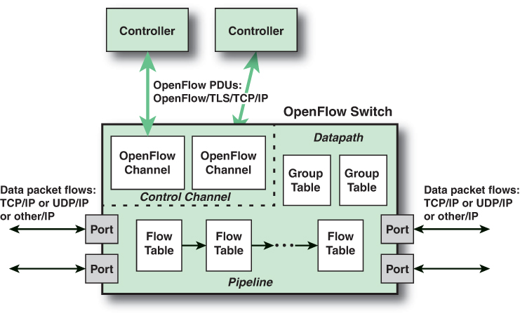
FIGURE 7.5 Main Components of an OpenFlow Switch
OpenFlow defines three types of ports:
Physical port: Corresponds to a hardware interface of the switch. For example, on an Ethernet switch, physical ports map one-to-one to the Ethernet interfaces.
Logical port: Does not correspond directly to a hardware interface of the switch. Logical ports are higher-level abstractions that may be defined in the switch using non-OpenFlow methods (e.g., link aggregation groups, tunnels, loopback interfaces). Logical ports may include packet encapsulation and may map to various physical ports. The processing done by the logical port is implementation dependent and must be transparent to OpenFlow processing. Logical ports must interact with OpenFlow processing in the same manner as OpenFlow physical ports.
Reserved port: Defined by the OpenFlow specification and specifies generic forwarding actions, such as sending to and receiving from the controller, flooding, or forwarding using non-OpenFlow methods, such as “normal” switch processing.
Within each switch, a series of tables are used to manage the flows of packets through the switch. The OpenFlow specification defines three types of tables in the logical switch architecture. A flow table matches incoming packets to a particular flow and specifies what functions are to be performed on the packets. There may be multiple flow tables that operate in a pipeline fashion, as explained shortly. A flow table may direct a flow to a group table, which may trigger a variety of actions that affect one or more flows. A meter table can trigger a variety of performance-related actions on a flow. Using the OpenFlow switch protocol, the controller can add, update, and delete flow entries in tables, both reactively (in response to packets) and proactively.
Before proceeding, it is helpful to define what is meant by the term flow. Curiously, this term is not defined in the OpenFlow specification, nor has there been an attempt to define it in virtually all of the literature on OpenFlow. In general terms, a flow is a sequence of packets traversing a network that share a set of header field values. For example, a flow could consist of all packets with the same source and destination IP addresses or all packets with the same virtual LAN (VLAN) identifier. We provide a more specific definition later in this chapter.
Flow Table Structure
The basic building block of the logical switch architecture is the flow table. Each packet that enters a switch passes through one of more flow tables. Each flow table consists of a number of rows, called entries, consisting of seven components (see Figure 7.6a). The entry components are as follows:
Match fields: These fields are used to select packets that match the values in the fields. The match fields (see Figure 7.6b) identify ingress and egress addresses at various protocol levels. Each of the fields in the match fields component either has a specific value or a wildcard value that matches any value in the corresponding packet header field. A flow table may include a table-miss flow entry, in which case wildcards match all fields (i.e., every field is a match, regardless of value), and the entry has the lowest priority.
Priority: This field shows the relative priority of table entries. It is a 16-bit field with 0 corresponding to the lowest priority. In principle, there could be 216 = 64,000 priority levels.
Counters: This field is updated for matching packets. The OpenFlow specification defines a variety of counters. Table 7.1 lists the required counters that must be supported by an OpenFlow switch.

FIGURE 7.6 OpenFlow Table Entry Formats
TABLE 7.1 Required OpenFlow Counters
Counter
Usage
Bit Length
Reference count (active entries)
Per flow table
32
Duration (seconds)
Per flow entry
32
Received packets
Per port
64
Transmitted packets
Per port
64
Duration (seconds)
Per port
32
Transmit packets
Per queue
64
Duration (seconds)
Per queue
32
Duration (seconds)
Per group
32
Instructions: This field contains instructions to be performed if a match occurs.
Timeouts: This field indicates the maximum amount of idle time before a flow is expired by the switch. Each flow entry has an idle_timeout and a hard_timeout associated with it. A nonzero hard_timeout field causes the flow entry to be removed after the given number of seconds, regardless of how many packets it has matched. A non-zero idle_timeout field causes the flow entry to be removed when it has matched no packets in the given number of seconds.
Cookie: This field contains a 64-bit opaque data value chosen by the controller. It may be used by the controller to filter flow statistics, flow modification, and flow deletion; it is not used when processing packets.
Flags: Flags alter the way flow entries are managed; for example, the flag OFPFF_SEND_FLOW_REM triggers Flow Removed messages (and removes the flow entry) for a flow entry.
It is now possible to offer a more precise definition of the term flow. From the point of view of an individual switch, a flow is a sequence of packets that matches a specific entry in a flow table. The definition is packet oriented in the sense that it is a function of the values of header fields of the packets that constitute the flow and not a function of the path the packets follow through the network. A combination of flow entries on multiple switches defines a flow that is bound to a specific path.
The instructions component of a table entry consists of a set of instructions that are executed if the packet matches the entry. Before describing the types of instructions, we need to define the terms action and action set. Actions describe packet forwarding, packet modification, and group table processing operations. The OpenFlow specification includes the following actions:
Output: This action forwards a packet to the specified port. The port could be an output port to another switch or the port to the controller. In the latter case, the packet is encapsulated in a message to the controller.
Set-Queue: This action sets the queue ID for a packet. When the packet is forwarded to a port using the output action, the queue ID determines which queue attached to this port is used for scheduling and forwarding the packet. Forwarding behavior is dictated by the configuration of the queue and is used to provide basic QoS support.
Group: This action processes a packet through the specified group.
Push-Tag/Pop-Tag: This action pushes or pops a tag field for a VLAN or Multiprotocol Label Switching (MPLS) packet.
Set-Field: The various Set-Field actions are identified by their field type and modify the values of the respective header fields in a packet.
Change-TTL: The various Change-TTL actions modify the values of the IPv4 TTL (time to live), IPv6 hop limit, or MPLS TTL in the packet.
Drop: There is no explicit action to represent drops. Instead, packets whose action sets have no output action should be dropped.
An action set is a list of actions associated with a packet that are accumulated while the packet is processed by each table and that are executed when the packet exits the processing pipeline.
The types of instructions can be grouped into four categories:
Direct packet through pipeline: The Goto-Table instruction directs a packet to a table farther along in the pipeline. The Meter instruction directs a packet to a specified meter.
Perform action on packet: Actions may be performed on a packet when it is matched to a table entry. The Apply-Actions instruction applies the specified actions immediately, without any change to the action set associated with this packet. This instruction may be used to modify the packet between two tables in the pipeline.
Update action set: The Write-Actions instruction merges specified actions into the current action set for this packet. The Clear-Actions instruction clears all the actions in the action set.
Update metadata: A metadata value can be associated with a packet. It is used to carry information from one table to the next. The Write-Metadata instruction updates an existing metadata value or creates a new value.
Flow Table Pipeline
A switch includes one or more flow tables. If there is more than one flow table, they are organized as a pipeline, with the tables labeled with increasing numbers starting with 0. The use of multiple tables in a pipeline, rather than a single flow table, provides the SDN controller with considerable flexibility.
The OpenFlow specification defines two stages of processing:
Ingress processing: Ingress processing always happens, and it begins with table 0 and uses the identity of the input port. Table 0 may be the only table, in which case the ingress processing is simplified to the processing performed on that single table, and there is no egress processing.
Egress processing: Egress processing is the processing that happens after the determination of the output port. It happens in the context of the output port. This stage is optional. If it occurs, it may involve one or more tables. The separation of the two stages is indicated by the numeric identifier of the first egress table. All tables with a number lower than the first egress table must be used as ingress tables, and no table with a number higher than or equal to the first egress table can be used as an ingress table.
Pipeline processing always starts with ingress processing at the first flow table: The packet must first be matched against flow entries of flow table 0. Other ingress flow tables may be used, depending on the outcome of the match in the first table. If the outcome of ingress processing is to forward the packet to an output port, the OpenFlow switch may perform egress processing in the context of that output port.
When a packet is presented to a table for matching, the input consists of the packet, the identity of the ingress port, the associated metadata value, and the associated action set. For Table 0, the metadata value is blank, and the action set is null. At each table, processing proceeds as follows:
If there is a match on one or more entries other than the table-miss entry, then the match is defined to be with the highest-priority matching entry. As mentioned in the preceding discussion, the priority is a component of a table entry and is set via OpenFlow; the priority is determined by the user or application invoking OpenFlow. The following steps may then be performed:
Step 1. Update any counters associated with this entry.
Step 2. Execute any instructions associated with this entry. This may include updating the action set, updating the metadata value, and performing actions.
Step 3. The packet is then forwarded to a flow table further down the pipeline, to the group table, to the meter table, or to an output port.
If there is a match only on a table-miss entry, the table entry may contain instructions, as with any other entry. In practice the table-miss entry specifies one of three actions:
Send the packet to the controller. This enables the controller to define a new flow for this and similar packets or decide to drop the packet.
Direct the packet to another flow table farther down the pipeline.
Drop the packet.
If there is no match on any entry and there is no table-miss entry, the packet is dropped.
For the final table in the pipeline, forwarding to another flow table is not an option. If and when a packet is finally directed to an output port, the accumulated action set is executed and then the packet is queued for output. Figure 7.7 illustrates the overall ingress pipeline process.
If egress processing is associated with a particular output port, then after a packet is directed to an output port at the completion of the ingress processing, the packet is directed to the first flow table of the egress pipeline. Egress pipeline processing proceeds in the same fashion as for ingress processing, except that there is no group table processing at the end of the egress pipeline.

FIGURE 7.7 Packet Flow Through an OpenFlow Switch: Ingress Processing
The Use of Multiple Tables
The use of multiple tables enables the nesting of flows or, put another way, it allows a single flow to be broken down into a number of parallel subflows. For example, an entry in Table 0 defines a flow consisting of packets traversing the network from a specific source IP address to a specific destination IP address. Once a least-cost route between these two endpoints is established, it may make sense for all traffic between these two endpoints to follow that route, and the next hop on that route from this switch can be entered in Table 0. In Table 1, separate entries for this flow can be defined for different transport-layer protocols, such as TCP and UDP. For these subflows, the same output port might be retained so that the subflows all follow the same route. However, TCP includes elaborate congestion control mechanisms not normally found with UDP, so it might be reasonable to handle the TCP and UDP subflows differently in terms of QoS-related parameters. Any of the Table 1 entries could immediately route its respective subflow to the output port, but some or all of the entries may invoke Table 2, further dividing each subflow.
Group Table
In the course of pipeline processing, a flow table may direct a flow of packets to the group table rather than to another flow table. The group table and group actions enable OpenFlow to represent a set of ports as a single entity for forwarding packets. Different types of groups are provided to represent different forwarding abstractions, such as multicasting and broadcasting.
Each group table consists of a number of rows, called group entries, each of which has four components (refer to Figure 7.6c):
Group identifier: This is a 32-bit unsigned integer that uniquely identifies the group. A group is defined as an entry in the group table.
Group type: This component determines the group semantics, as explained later in this chapter.
Counters: This component is updated when packets are processed by a group.
Action buckets: This is an ordered list of action buckets, where each action bucket contains a set of actions to execute and associated parameters.
Each group includes a set of one or more action buckets. Each bucket contains a list of actions. Unlike the action set associated with a flow table entry, which is a list of actions that accumulate while the packet is processed by each flow table, the action list in a bucket is executed when a packet reaches a bucket. The action list is executed in sequence and generally ends with the output action, which forwards the packet to a specified port. The action list may also end with the group action, which sends the packet to another group. This enables the chaining of groups for more complex processing.
OpenFlow Protocol
The OpenFlow protocol describes message exchanges that take place between an OpenFlow controller and an OpenFlow switch. Typically, the protocol is implemented on top of TLS, providing a secure OpenFlow channel.
The OpenFlow protocol enables the controller to perform add, update, and delete actions to the flow entries in the flow tables. It supports three types of messages:
Controller-to-switch: These messages are initiated by the controller and, in some cases, require a response from the switch. This class of messages enables the controller to manage the logical state of the switch, including its configuration and details of flow and group table entries. Also included in this class is the packet-out message, which is sent by the controller to a switch when that switch sends a packet to the controller and the controller decides not to drop the packet but to direct it to a switch output port.
Asynchronous: These types of messages are sent without solicitation from the controller. This class includes various status messages to the controller. Also included is the packet-in message, which may be used by the switch to send a packet to the controller when there is no flow table match.
Symmetric: These messages are sent without solicitation from either the controller or the switch. They are simple yet helpful. Hello messages are typically sent back and forth between the controller and switch when the connection is first established. Echo request and reply messages can be used by either the switch or controller to measure the latency or bandwidth of a controller-switch connection or just verify that the device is up and running. The experimenter message is used to stage features to be built in to future versions of OpenFlow.
In general terms, the OpenFlow protocol provides the SDN controller with three types of information to be used in managing the network:
Event-based messages: Sent by the switch to the controller when a link or port change occurs.
Flow statistics: Generated by the switch based on traffic flow. This information enables the controller to monitor traffic, reconfigure the network as needed, and adjust flow parameters to meet QoS requirements.
Encapsulated packets: Sent by the switch to the controller either because there is an explicit action to send this packet in a flow table entry or because the switch needs information for establishing a new flow.
The OpenFlow protocol enables the controller to manage the logical structure of a switch without regard to the details of how the switch implements the OpenFlow logical architecture.
7.5 SDN Control Plane
The SDN control layer maps application-layer service requests into specific commands and directives to data plane switches and supplies applications with information about data plane topology and activity. The control layer is implemented as a server or cooperating set of servers known as SDN controllers. This section provides an overview of control plane functionality.
Control Plane Functions
Figure 7.8 illustrates the functions performed by SDN controllers.
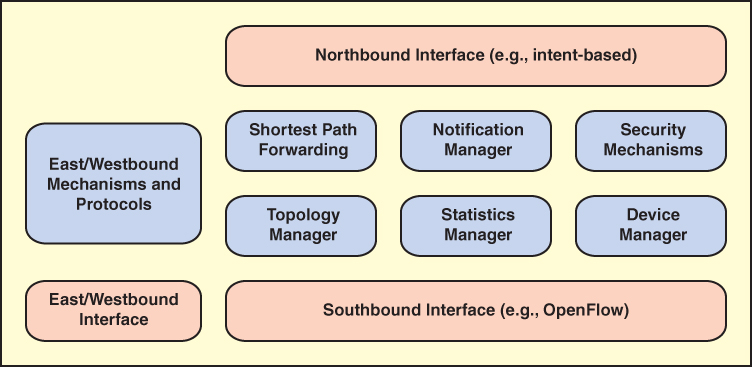
FIGURE 7.8 SDN Control Plane Functions and Interfaces
The figure illustrates the essential functions that any controller should provide, which include the following:
Shortest path forwarding: Uses routing information collected from switches to establish preferred routes.
Notification manager: Receives, processes, and forwards to an application events such as alarm notifications, security alarms, and state changes.
Security mechanisms: Provide isolation and security enforcement between applications and services.
Topology manager: Builds and maintains switch interconnection topology information.
Statistics manager: Collects data on traffic through the switches.
Device manager: Configures switch parameters and attributes and manages flow tables.
The functionality provided by the SDN controller can be viewed as a network operating system (NOS).2 As with a conventional OS, an NOS provides essential services, common APIs, and an abstraction of lower-layer elements to developers. The functions of an SDN NOS, such as those listed above, enable developers to define network policies and manage networks without concern for the details of the network device characteristics, which may be heterogeneous and dynamic. The northbound interface, discussed subsequently, provides a uniform means for application developers and network managers to access SDN service and perform network management tasks. Further, well-defined northbound interfaces enable developers to create software that is not only independent of data plane details but to a great extent usable with a variety of SDN controller servers.
2. An NOS is a server-based operating system oriented to computer networking. It may include directory services, network management, network monitoring, network policies, user group management, network security, and other network-related functions.
Southbound Interface
The functionality of the control plane is visible through four interfaces, which are given geographic names [LATI20]. The southbound interface (SBI) provides the logical connection between the SDN controller and the data plane switches, as shown in Figure 7.9. Some controller products and configurations support only a single southbound protocol. A more flexible approach is the use of a southbound abstraction layer that provides a common interface for the control plane functions while supporting multiple southbound APIs.

FIGURE 7.9 SDN Controller Interfaces
The most commonly implemented southbound API is OpenFlow.
Northbound Interface
The northbound interface (NBI) enables applications to access control plane functions and services without needing to know the details of the underlying network switches. The northbound interface is typically viewed as a software API rather than as a protocol.
Unlike OpenFlow for the SBI, there is no single API or protocol that different developers/vendors can use for the northbound interface. One reason for this lack of standardization is the variation in applications and their requirements. However, there is consensus on the architectural approach known as intent NBI, and a number of open source SDN packages use it [PHAM16].
There are essentially two approaches for developing an NBI:
Prescriptive: The application specifies or constrains the selection and allocation, virtualization and abstraction, or assembly and concatenation of resources needed to satisfy the request.
Nonprescriptive: This is also referred to as intent NBI. The application describes its requirements in application-oriented language, and the controller becomes an intelligent black box that integrates core network services to construct network applications to serve users’ requests.
An important reference on intent NBI is a document issued by the Open Networking Foundation [ONF16], which describes the intent NBI paradigm, its utility and properties, and its potential implementation structure. Figure 7.10, from that document, provides a schematic representation of the architecture.
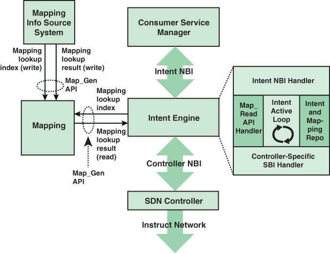
FIGURE 7.10 Schematic Representation of Intent NBI Architecture
The architecture makes use of mappings that can translate intent NBI requests into forms that lower-level entities can understand. Mappings are an information intermediation mechanism that effectively permits consumer and provider systems to communicate in terms that are natural to each. The intent environment is dynamic. The intent system, which is essentially middleware between applications and the SDN controller, continuously evaluates the relationship among a number of elements:
Existing and new intent requests
Mappings
Controlled resource sets and states
The intent engine in Figure 7.10 is a middleware component that has an NBI interface with the controller and an NBI interface with the applications that are managed by a consumer service manager component. The intent engine has five major components:
Information repository (repo): This contains the set of active service intents and mapping lookup values.
Map_Read API handler: This is responsible for reflecting to the repo an up-to-date capture of mapping lookup values.
Intent NBI handler: This is responsible for receiving service intents from the consumer system and reflecting them to the repo (in native form) and for reflecting notifications to the consumer system.
Intent active loop: This element is responsible for continuously evaluating active service intents and mappings from the repo and network information from the SBI handler and taking actions required to instantiate new, or appropriately modify existing, service configurations as a function of detected intent changes (repo), and/or of mapping changes (repo), and/or of network changes (reflected by the SBI handler). Computing appropriate inputs to be reflected to the SBI handler results in the following:
Inputs to the SBI handler may adhere to some model-based form, such as specifying one or more pairs of endpoints for piece-wise interconnection, along with parametric constraints on such interconnections. The function of the intent active loop would then include any required and appropriate parsing and translation of intent request terms into such model form. Instructions relayed to the SBI handler would be based on this model and use the specific terms that result from mapping lookups.
Where network conditions do not permit instructions that deliver all aspects of specified service intents, appropriate notifications are synthesized to be reflected to the intent NBI handler.
Controller-specific SBI handler: This is the only controller-specific component of the intent engine and has the following functions:
It receives inputs from the intent active loop and provides an appropriately modified form of those inputs, as provisioning instructions, to the SDN controller.
It receives information (e.g., topology information) from the SDN controller and forwards it to the intent active loop in an appropriately modified form.
The figure also depicts a mapping information source system. Conceptually, this system associates intent NBI–specific terms, called keys or indices, with controller NBI objects and operations.
This architecture has a number of strengths and benefits:
Intent declarations are declarative and serve to separate consumer and provider system implementations. They are intended to make human and/or machine consumer requests that are forwarded to provider systems as simple as possible. The SDN controller can calculate the optimal result to fulfill the intent request.
The intent request is independent of the controller platforms and implementations. It only expresses the requirements for the application layer and uses application-related vocabulary and information. One intent request can be implemented on different controllers with various algorithms. This makes applications portable.
The intent NBI approach may reduce resource allocation conflicts. Because intent NBI requests do not indicate specific resources to be allocated to specific services, the provider can assign resources to services in ways that reduce the possibility of resource contention.
An example of the types of objects that can be referenced in intent declarations is provided in the intent framework ONOS, which is an open source SDN controller. An intent describes an application’s request to the ONOS core to alter the network’s behavior. At the lowest levels, intents may be described in terms of:
Network resources: A set of object models, such as links, that tie back to the parts of the network affected by an intent.
Constraints: Weights applied to a set of network resources, such as bandwidth, optical frequency, and link type.
Criteria: Packet header fields or patterns that describe a slice of traffic. For example, an intent’s TrafficSelector carries criteria as a set of objects that implement the Criterion interface.
Instructions: Actions to apply to a slice of traffic, such as header field modifications or outputting through specific ports. For example, an intent’s TrafficTreatment carries instructions as a set of objects that implement the Instruction interface.
Eastbound Interface
Eastbound interfaces are used to import and export information among distributed controllers. The eastbound interface supports the creation of multiple domains. In a large enterprise network, the deployment of a single controller to manage all network devices would be unwieldy or undesirable. A more likely scenario is that the operator of a large enterprise or carrier network divides the whole network into a number of nonoverlapping SDN domains, as shown in Figure 7.11.

FIGURE 7.11 SDN Domain Structure
Reasons for using SDN domains include the following:
Scalability: The number of devices an SDN controller can feasibly manage is limited. Thus, a reasonably large network may need to deploy multiple SDN controllers.
Privacy: A carrier may choose to implement different privacy policies in different SDN domains. For example, an SDN domain may be dedicated to a set of customers that implement their own highly customized privacy policies, requiring that some networking information in this domain (e.g., network topology) should not be disclosed to an external entity.
Incremental deployment: A carrier’s network may consist of portions of legacy and nonlegacy infrastructure. Dividing the network into multiple individually manageable SDN domains allows for flexible incremental deployment.
The existence of multiple domains creates a requirement for individual controllers to communicate with each other via a standardized protocol to exchange routing information. No single approach has gained widespread acceptance, and there have been a wide variety of implementations on both open source and proprietary systems [LATI20].
Westbound Interface
The westbound interface enables communication between an SDN controller and a non-SDN network. These interfaces typically use Border Gateway Protocol (BGP) to bridge the gap between SDN and traditional networks.
7.6 SDN Application Plane
The power of the SDN approach to networking is in the support it provides for network applications to monitor and manage network behavior. The SDN control plane provides the functions and services that facilitate rapid development and deployment of network applications.
While the SDN data and control planes are well defined, there is much less agreement on the nature and scope of the application plane. At minimum, the application plane includes a number of network applications—that is, applications that specifically deal with network management and control. There is no agreed-upon set of such applications or even categories of such applications. Further, the application layer may include general-purpose network abstraction tools and services that might also be viewed as part of the functionality of the control plane.
Application Plane Architecture
The application plane contains applications and services that define, monitor, and control network resources and behavior. These applications interact with the SDN control plane via application control interfaces in order for the SDN control layer to automatically customize the behavior and the properties of network resources. The programming of an SDN application makes use of the abstracted view of network resources provided by the SDN control layer by means of information and data models exposed via the application control interface.
This section provides an overview of application plane functionality, which is illustrated in Figure 7.12.
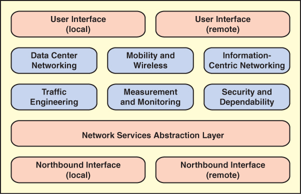
FIGURE 7.12 SDN Application Plane Functions and Interfaces
Northbound Interface
As described in Section 7.5, the northbound interface enables applications to access control plane functions and services without needing to know the details of the underlying network switches. Typically, the northbound interface provides an abstract view of network resources controlled by the software in the SDN control plane.
Figure 7.12 indicates that the northbound interface can be a local or remote interface. For a local interface, the SDN applications are running on the same server as the control plane software (i.e., the controller network operating system). Alternatively, the applications can be run on remote systems, in which case the northbound interface is a protocol or an API that connects the applications to the controller NOS running on a central server. Both architectures are likely to be implemented.
Network Services Abstraction Layer
RFC 7426 (Software-Defined Networking [SDN]: Layers and Architecture Terminology, January 2015) from the Internet Engineering Task Force (IETF) defines a network services abstraction layer between the control and application planes and describes it as a layer that provides service abstractions that can be used by applications and services. Several functional concepts are suggested by the placement of this layer in the SDN architecture:
This layer could provide an abstract view of network resources that hides the details of the underlying data plane devices.
This layer could provide a generalized view of control plane functionality so that applications could be written that would operate across a range of controller network operating systems. This functionality is similar to that of a hypervisor or virtual machine monitor that decouples applications from the underlying OS and underlying hardware.
This layer could provide a network virtualization capability that allows different views of the underlying data plane infrastructure.
Arguably, this layer could be considered to be part of the northbound interface, with the functionality incorporated in the control plane or the application plane.
A wide range of schemes have been developed that roughly fall into this layer, although discussing them is beyond the scope of this chapter.
Network Applications
Many network applications could be implemented for a software-defined network. Different published surveys of SDN have come up with different lists and even different general categories of SDN-based network applications. Figure 7.12 includes six categories that encompass the majority of SDN applications. The following sections discuss these six categories.
Traffic Engineering
Traffic engineering involves dynamically analyzing, regulating, and predicting the behavior of data flowing in networks with the aim of performance optimization to meet service-level agreements (SLAs). Traffic engineering involves establishing routing and forwarding policies based on QoS requirements. With SDN, the task of traffic engineering should be considerably simplified compared to in a non-SDN network. SDN offers a uniform global view of heterogeneous equipment and powerful tools for configuring and managing network switches.
Traffic engineering is an area of great activity in the development of SDN applications. [KREU15] lists the following application types that have been implemented as SDN applications:
On-demand virtual private networks
Load balancing
Energy-aware routing
QoS for broadband access networks
Scheduling/optimization
Traffic engineering with minimal overhead
Dynamic QoS routing for multimedia apps
Fast recovery through fast-failover groups
QoS policy management framework
QoS enforcement
QoS over heterogeneous networks
Multiple packet schedulers
Queue management for QoS enforcement
Divide and spread forwarding tables
Measurement and Monitoring
The area of measurement and monitoring applications can roughly be divided into two categories: applications that provide new functionality for other networking services and applications that add value to OpenFlow-based SDNs.
An example of the first category is in the area of broadband home connections. If a connection is to an SDN-based network, new functions can be added to the measurement of home network traffic and demand, allowing the system to react to changing conditions. The second category typically involves using different kinds of sampling and estimation techniques to reduce the burden of the control plane in the collection of data plane statistics.
Security and Dependability
Security and dependability applications have one of two goals:
Address security concerns related to the use of SDN: SDN involves a three-layer architecture (application, control, and data layers) and new approaches to distributed control and data encapsulation. All of this introduces the potential for new vectors for attack. Threats can occur at any of the three layers or in the communication between layers. SDN applications are needed to provide for the secure use of SDN.
Use the functionality of SDN to improve network security: Although SDN presents new security challenges for network designers and managers, it also provides a platform for implementing consistent, centrally managed security policies and mechanisms for the network. SDN allows the development of SDN security controllers and SDN security applications that can provision and orchestrate security services and mechanisms.
Data Center Networking
The three areas of SDN applications discussed so far—traffic engineering, measurement and monitoring, and security—relate to a broad range of use cases in many different kinds of networks. The remaining three applications areas in Figure 7.12—data center networking, mobility and wireless, and information-centric networking—have use cases in specific types of networks.
Cloud computing, big data, large enterprise networks, and even, in many cases, smaller enterprise networks depend strongly on highly scalable and efficient data centers. [KREU15] lists the following as key requirements for data centers: high and flexible cross-section bandwidth3 and low latency, QoS based on application requirements, high levels of resilience, intelligent resource utilization to reduce energy consumption and improve overall efficiency, and agility in provisioning network resources (e.g., by means of network virtualization and orchestration with computing and storage).
3. Cross-section bandwidth is the maximum bidirectional data rate that can pass between two parts of a network that is divided into two equal halves.
With traditional network architectures, many of these requirements are difficult to satisfy because of the complexity and inflexibility of the network. SDN offers the promise of substantial improvement in the ability to rapidly modify data center network configurations, to flexibly respond to user needs, and to ensure efficient operation of the network.
Mobility and Wireless
In addition to all the traditional performance, security, and reliability requirements of wired networks, wireless networks impose a broad range of new requirements and challenges. Mobile users are continuously generating demands for new services with high quality and efficient content delivery, independent of location. Network providers must deal with problems related to managing the available spectrum, implementing handover mechanisms, performing efficient load balancing, responding to QoS and QoE requirements, and maintaining security.
SDN can provide much-needed tools for a mobile network provider, and in recent years, a number of SDN-based applications for wireless network providers have been designed. Among others, [KREU15] lists the following SDN application areas: seamless mobility through efficient handovers, creation of on-demand virtual access points, load balancing, downlink scheduling, dynamic spectrum usage, enhanced inter-cell interference coordination, per-client and/or per-base station resource block allocations, simplified administration, easy management of heterogeneous network technologies, interoperability between different networks, shared wireless infrastructures, and management of QoS and access control policies.
Information-Centric Networking
Information-centric networking (ICN), also known as content-centric networking, has received significant attention in recent years, mainly driven by the fact that distribution and manipulation of information have become the major functions of the Internet. Unlike in the traditional host-centric networking paradigm, where information is obtained by contacting specified named hosts, ICN is aimed at providing native network primitives for efficient information retrieval by directly naming and operating on information objects.
With ICN, there is a distinction between location and identity, thus decoupling information for its sources. With this approach, information sources can place, and information users can find, information anywhere in the network because the information is named, addressed, and matched independently of its location. In ICN, instead of a source/destination host pair being specified for communication, a piece of information is named. In ICN, after a request is sent, the network is responsible for locating the best source that can provide the desired information. Routing of information requests thus seeks to find the best source for the information, based on a location-independent name.
Deploying ICN on traditional networks is challenging because existing routing equipment needs to be updated or replaced with ICN-enabled routing devices. Further, ICN shifts the delivery model from a host-to-user model to a content-to-user model. This creates a need for clear separation between the task of information demand and supply and the task of forwarding. SDN has the potential to provide the necessary technology for deploying ICN because it provides for programmability of the forwarding elements and a separation of the control and data planes.
A number of projects have proposed using SDN capabilities to implement ICNs. There is no consensus approach to achieving this coupling of SDN and ICN. Suggested approaches include substantial enhancements/modifications to the OpenFlow protocol, developing a mapping of names into IP addresses using a hash function, using the IP option header as a name field, and using an abstraction layer between an OpenFlow switch and an ICN router, so that the layer, the OpenFlow switch, and the ICN router function as a single programmable ICN router.
User Interface
The user interface enables a user to configure parameters in SDN applications and to interact with applications that support user interaction. Again, there are two possible interfaces. A user that is collocated with the SDN application server (which may or may not include the control plane) can use the server’s keyboard/display. More typically, a user logs on to the application server over a network or communications facility.
7.7 Key Terms and Review Questions
Key Terms
application programming interface (API) network operating system (NOS) network services abstraction layer |
Review Questions
1. List the key requirements for a modern networking approach.
2. How does SDN split the functions of a switch?
3. Describe the elements of an SDN architecture.
4. Explain the function of the northbound, southbound, eastbound, and westbound interfaces.
5. What are the two main data plane functions?
6. Explain the difference between an OpenFlow switch, an OpenFlow port, and an OpenFlow channel.
7. Explain the difference between an OpenFlow physical port, an OpenFlow logical port, and an OpenFlow reserved port.
8. Explain the difference between an OpenFlow flow table, an OpenFlow group table, and an OpenFlow meter table.
9. Define flow.
10. Define action and action set.
11. Describe OpenFlow ingress and egress processing.
12. List and briefly define the essential functions of an SDN controller.
13. Characterize the operation of an intent NBI.
14. List key reasons for using SDN domains.
15. Describe the application plane architecture.
16. What is the purpose of a network services abstraction layer?
17. List and briefly describe six network application areas.
7.8 References and Documents
References
KREU15 Kreutz, D., et al. “Software-Defined Networking: A Comprehensive Survey.” Proceedings of the IEEE, January 2015.
LATI20 Latif, Z., et al. “A Comprehensive Survey of Interface Protocols for Software Defined Networks.” Journal of Network and Computer Applications, volume 145, April 15, 2020.
ODCA14 Open Data Center Alliance. Open Data Center Alliance Master Usage Model: Software-Defined Networking Rev. 2.0. ODCA white paper. 2014.
ONF12 Open Networking Foundation. Software-Defined Networking: The New Norm for Networks. ONF white paper, April 12, 2012.
ONF15 Open Networking Foundation. OpenFlow Switch Specification Version 1.5.1. March 26, 2015.
ONF16 Open Networking Foundation. Intent NBI: Definition and Principles. ONF-TR-523, October 2016.
PHAM16 Pham, M., and Hoang, D. “SDN Applications: The Intent-Based Northbound Interface Realisation for Extended Applications.” 2016 IEEE NetSoft Conference and Workshops, May 2016.
STAL16 Stallings, W. Foundations of Modern Networking: SDN, NFV, QoE, IoT, and Cloud. Upper Saddle River, NJ: Pearson Addison Wesley, 2016.
Documents
RFC 7426 Software-Defined Networking (SDN): Layers and Architecture Terminology. January 2015.
ITU-T Y.3300 Framework of Software-Defined Networking. June 2014.