Control Rig Setup for a Biped Character: IK and FK

Character by Mark McDonald (2007).
Former Student Spotlight: Ryan Yokley
Zen and the Art of Rig Planning
When creating a rig for their own personal short films, most animators tend to grant themselves a large amount of wiggle room when it comes to laying out controls and custom interfaces to interact with their rigs. If you’re the only person who is ever going to be fiddling around with the character, you can just modify the controls as you’re going along, right? I mean, what problems could that possibly generate 6 months from now when you’re animating scene 35 of 60 of your thesis masterwork? Ok, you probably sensed the regret there.
Granted, there is a level of rigging that remains protean by necessity; it’s difficult to predict all of the functionality an animator or, help us, a team of them will need during the production cycle. But planning ahead, especially working within a studio production pipeline, is probably the most vital step when creating a comprehensive rig/control scheme for a character – one that will keep things moving smoothly under a tight deadline and won’t require the pipeline to come to a screeching halt every time a tiny change needs to be made to the character. In other words, taking the time to plan out your control scheme is a good habit to get into.
While tricks like file referencing have given some leeway to the once extreme rigidity of initial character setup, it’s important to keep in mind how fast things often have to flow in a production pipeline to meet deadlines. In my limited experience, this is key in the game industry. Large changes to the rig often dictate adjusting massive amounts of in-game animation. So in whatever project you’ve got planned, get the animators together with the script and figure out what they are going to need. If it’s just you, sit down with your script and figure out what you are going to need before you dive into animation.
Unfortunately, in the game industry, changes are often dictated outside of the framework of the animation team. Sometimes memory, programming, or engineering complexities require late changes to the skeleton. However, as suggested by a senior co-worker of mine, aim high when creating your rig and your skeleton, because it’s actually easier to downsize complexity later than it is to try to add functionality.
Ryan Yokley received his Bachelor’s degree in Studio Art from Florida State University in 2002 and his MFA in Animation at the Savannah College of Art and Design in 2006. He has contributed his animation and rigging work to several award winning animated shorts including “The Machine” (Siggraph 2004 SPACE second place in Visual Effects category) and “The Audition” (Siggraph 2005 SPACE first place for Visual Effects category). Ryan did his internship at Vinton Studios (now Laika) in Portland, Oregon, in 2004. The project created by the intern team at Vinton was featured in the October 2004 issue of Animation Magazine. Since then Ryan has been working as a character animator at Rainbow Studios, a division of THQ, in Phoenix, Arizona. His work can be seen at: www.lineofaction.com.

Trigger by Ryan Yokley (2002).

Control Rig Workflow.
Now that there is a skeletal structure inside of the character, a control system will be needed to make the animation process easier. Setting a keyframe on joints directly while animating can be cumbersome, making productive animation both difficult and time-consuming. Maya has a series of tools that can be used to build a customizable control system, or rig. The goal of a good character rig is to give animators simplified, intuitive control over their character’s skeleton, so that the character can be posed and animated easily. This chapter will introduce several approaches and discuss how they are commonly used to create the character rig. The assignments that follow will utilize these techniques to create a basic rig, with a few extras that make the animation process easier. It is important to remember that the approaches shown in this book are not the only way to create a rig. My goal is to give you a variety of approaches that can be adapted for different needs. Before you can explore more advanced control systems, I hope to provide the good foundation necessary for a more complex rig later.
Before we can create controls, however, there needs to be a basic understanding of how things work during the animation process. Animation, by definition, is the ability to make something appear alive through movement. Movement can be created by calculating a change from one position in space to another, using translate, rotate, and scale. Joints are usually rotated to achieve a natural motion when animating a skeleton. When a hierarchy exists, such as with a joint chain, these rotations must be calculated not only for the joint rotated, but for the rest of the hierarchy as well. There are two methods for calculating the positions of the hierarchy during animation – forward kinematics or inverse kinematics. Each method affects the hierarchy differently.

Eyeball man by Neil Helm (2005).
In a nutshell, kinematics is the study of motion. More specifically, it is the section of physics that deals with motion without any application of force and mass. Kinematics is not only movement, but the consideration of how things move. In animation, there are two kinematical systems in place – forward kinematics and inverse kinematics.
Forward kinematics, or FK, is a method where a hierarchy of joints (or objects) is rotated one at a time to create a pose. A key is then set on the rotation channels for each joint (or object). The position of a joint in the hierarchy is calculated based on the positions of each and every joint above. For example, in order to position the wrist, the animator must first consider the position of the torso, the shoulder, and the elbow (from the top of the hierarchy down, in a forward direction). If a character’s arm is moving, the wrist is affected by the elbow, which is affected by the shoulder. Any movement in the character’s spine would also affect the position of the entire arm.

Rotating the spine (right image) with an FK arm repositions the entire arm.
One of the biggest challenges for FK is that it is pretty much impossible to fix a joint in space, as any movement above that joint in the hierarchy would move the joint out of place.
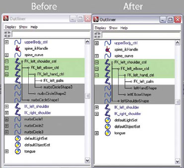
Because it is difficult to select joints when animating, a control system is created to make the selection easier. A NURBS curve is usually used, and the curve is used to control the joint. There are several tools available (discussed later in this chapter) that allow the curve to control the joint. The best way that I have come across, however, is to use a MEL command to parent the shape of a NURBS curve to the transform node of a joint. (I first heard of this during Jason Schliefer’s Maya Masterclasses on Animator Friendly Rigging, but I have done some research and found multiple sources for this approach, so I’m not actually sure where this idea originated. Check out his DVD series available on Autodesk’s website, a great step after understanding this book!) This MEL script actually makes the NURBS curve the shape node of the joint (joints do not have shape nodes associated with them, so we have the ability to assign one with the MEL command). The MEL command is as follows:
parent -add -shape nurbsCircleShape1 joint1;
where nurbsCircleShape1 is the name of the NURBS curve and joint1 is the name of the joint.
Inverse Kinematics
Inverse kinematics, or IK, is a mathematical system that calculates the rotations of a joint chain from the identified start joint all the way to the established end joint of the chain. An IK handle is created at the end of the chain that allows the animator to position the location of the end of a limb. Because of this, IK is a more intuitive way of positioning a character, much like a digital puppet. Once the handle is positioned, the calculations then occur to position the rest of the chain based on the location of the end joint, all the way back up to the start joint (from the bottom of the hierarchy up, or in an inverse direction).
IK enables a character the ability to plant its feet on the ground and remain there when moving the body. This is commonly referred to as stickiness, which is very difficult to achieve using FK. When animating, IK is used when stickiness is needed or when movement is driven from the bottom of the limb; that is, feet planted on the ground (feet stick because of the IK solver in the legs and feet), character pushing against something (hands stick because of the IK solver in the arms and hand), a character throwing a ball (a wrist driven motion with IK in the arms).
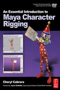
IK in the legs and feet provide the ability to keep the feet planted on the ground when moving the torso down (right image).
Because IK solvers have a tendency to break, or stop solving, while animating, IK handles should never be keyframed directly. Always control IK handles indirectly with a control system. The single chain (SC) or rotate plane (RP) solvers can be controlled by constraining or parenting the IK handle to an object, such as a group node, locator, or a NURBS curve. The Spline IK curve can be controlled using deformers, such as joints or clusters, which can also be parented to a NURBS controller. These approaches will be explored during the assignments for this chapter.
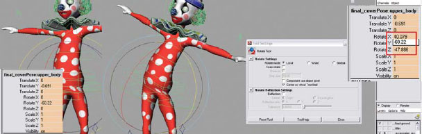
When creating IK handles, Maya automatically creates an IK/FK blend system, which allows you to switch back and forth between IK and FK while animating. This built-in blend system is not 100% reliable and sometimes causes awkward flipping of the joint chain during the blend. We will not be covering the built-in system in this edition. Instead, we will look at building a three joint chain blend, which is a much more traditional and reliable way of switching between IK and FK.
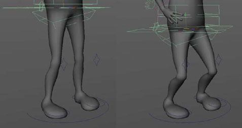
A three joint chain blend. The image on the left is the IK control, the image in the middle is the mid-blend position, and the image on the right is the FK control. The geometry is controlled by the third joint chain, which blends between the IK and the FK control arms.
Usually, a series of IK chains are used through a single joint hierarchy in order to create the control necessary for a limb. For example, a single IK chain from the hip to the toe would not work for the control needed in the leg and foot. The toes, the ankle, and the leg need to be able to move independently from each other. In order to accomplish this, three separate IK chains need to be created and then parented into a hierarchy for maximum control.
The most commonly used IK solvers in Maya for biped setup are the SC solver, the RP solver, and the Spline IK solver. It is important to understand the differences as well as when and why to use each solver.
The SC and the RP solvers are similar in that they both calculate the rotations of all of the joints in an IK chain. The major difference is that the RP solver includes additional control for the ability to change the orientation of the joint chain from the start joint. To demonstrate the difference, imitate the pictures below. Hold your arm out straight and parallel to the floor (the beginning joint chain). Bend your elbow so that your wrist moves toward your shoulder keeping your elbow parallel to the floor (this demonstrates the rotations of the joint chain for both SC and RP solvers). Now rotate your shoulder and bring your elbow down (this demonstrates the change in the orientation of the joint chain for the RP solver by rotating the plane from the shoulder – the start joint of the chain). The SC solver is usually used in the hands and feet, while the RP solver is usually used in the arms and legs.

The character’s right leg (your left) has an SC solver running through the joint chain. The character’s left leg (your right) has an RP solver, which provides the additional ability of rotating the knee from the hip joint.
![]()
Make sure to set preferred angles in joints where you are running SC or RP IK. A preferred angle tells Maya which direction the joint should bend when an IK solver runs through it. If you do not, when you move the IK handle, the joint will bend in the wrong direction, or not bend at all. To set a preferred angle, select the joint in the center of the chain (such as an elbow or knee), rotate it in the direction it should bend, choose the joint ABOVE that joint in the hierarchy, then go to [Skeleton > Set Preferred Angle]. You can then return the rotated joint back to zero by clicking on it and typing 0 in the rotation channels of the channel box.

The character’s spine is controlled by an IK spline solver.
The Spline IK solver is a completely different solver than the RP or SC. The Spline IK handle does NOT directly control the position of the chain. Instead, a NURBS spline curve runs through the identified joint chain. By moving the curve, or control vertices (CVs) on the curve, the solver then positions the joints based on the new shape or position of the curve. This solver is best used for long joint chains such as those needed in the neck, spine, or tail.
Creating controllers from NURBS curves seems to be the most popular way to control a character rig. By using all NURBS curves, it is possible to drag select all controllers simultaneously which can speed up the keyframing process when animating. Additional attributes can be added to the curves for customizable control. There are several ways of linking the NURBS curves with attributes that need control.
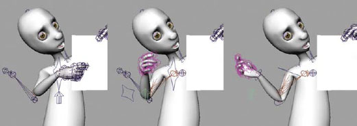
The character’s controllers are all made with NURBS curves.
Rotation Order
Before beginning any discussion about creating associations for control, there really needs to be an understanding about rotation order. Having the correct rotation order on controllers is probably the most important thing when it comes to actually animating with a control rig. To make sure that everything works properly, rotation order needs to be established for joints and FK controls in the very beginning of the setup process. FK control should always be set up before IK, especially if it is an FK/IK control system. The reason for this is that IK begins to place rotations on the joints the moment the solver is placed. This can lead to problems with the FK control setup. So, what exactly is rotation order and why is it so important?
Objects in a 3D environment rotate in either a quaternion rotation method or Euler rotation method. The default method (which we will be using) is Independent Euler-Angle Curves, which calculates the rotation according to the degree set along the X, Y, and Z axis but evaluates the rotation based on the chosen rotation order. The rotation order establishes how the object orients when rotating the object from one position to the next. The default rotational order on all objects in Maya is XYZ.
In order to see how the rotations work you must change your rotate tool mode to Gimbal by double-clicking on the rotate tool button to open the tool settings window and set the rotate tool rotate mode to “Gimbal”. The rotate tool options have three rotate modes: Local, World, and Gimbal. When an object is selected, the rotate tool allows interactive rotation by click-holding on a colored ring and dragging the mouse to rotate.

The rotate tool settings window.
However, in Local and World modes, this rotation is not accurate along the specified colored rings. We don’t always truly rotate along the specified axis for that color (X:red, Y:green, Z:blue). Sometimes more than one rotational value of the object being rotated may change in the XYZ channels in the channel box. When animating, this can be a serious problem and cause all kinds of unpredictable rotational behavior. In Gimbal mode, only a single X, Y, or Z rotation axis value in the channel box will change when clicking on the specified color ring. Gimbal mode is the ONLY mode that shows you exactly what happens.
After rotating the character in Local mode on the Y axis, further rotation on the Z axis also causes the X axis to rotate.
To see what on earth I am talking about, create a sphere in Maya. With the sphere selected, change your rotate tool to Gimbal, and click on the X axis (red ring) of the rotate tool ring and rotate it. You will notice that nothing is affected. The rotate tool looks exactly the same as before we rotated the X axis. Because X is first in the rotation order, it does not affect any of the other axes.

Rotating the sphere in Gimbal mode on the X axis.
If you rotate the Z axis (blue ring), it carries both the X and Y axes with it because it is last in the rotation order, so it affects both of the other axes.
Now, if you rotate the Y axis (green ring) you will notice that the X is carried with the Y, and if the Y axis is rotated 90 degrees, the X axis now lines up with the Z axis. At this point you are now unable to rotate the sphere toward the front or back of 3D space because both the X and Z axes rotate the sphere side to side. This is what is referred to as Gimbal lock, and it can cause some pretty huge frustrations for an animator. Changing the tool back to Local or World mode seems to solve the ability to rotate, but then we are back to inaccurate rotations in multiple axes, which causes crazy flipping during the animation and much more frustration for the animator.

Rotating the sphere in Gimbal mode on the Z axis carries both the X and Y axis rings with it.
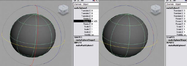
Rotating the sphere in Gimbal mode on the Y axis (left) carries the X axis ring with it – all the way to Gimbal lock (right).
So what is an animator to do? Knowing what to do to fix the issue is helpful, but here is where workflow is a huge concern. The correct rotation order must be chosen while the FK controls are being set up, otherwise the other tools (like constraints, set driven keys, and IK) that were used to make the rig easier to work with simply won’t work anymore. FK Rotational Orders must be established before the other things are set up.
So when you create your FK controls, it is important to think about how that control will be used during animation then set the joint and controller appropriately. The easiest way to figure out which order you will need is to try it out on a sample skeleton and change the orders around. There really is no “only” way of setting these. There is simply preference. In my opinion, the most important rotation should go last (all the way to the right), since it carries the other two rotations with it. The first axis (all the way to the left) should be the least important as it affects only itself.
So, think about which direction the object moves the most. For example, a head turns left to right most often, so that would be rotating on the Y axis. Then I would say for the next motion, the head goes up and down most frequently (or rotating on the X axis). Lastly, the head tilts left to right, rotating along the Z axis. So I would choose a rotation order of ZXY for the head controller.
Don’t worry too much if this is getting a bit confusing. This is one concept that does take some time to sink into your brain and understand. I have included my preferences in the assignments, but feel free to change them as you deem necessary.
Connection Editor [Window > General Editors > Connection Editor]
The connection editor allows you to take one attribute (referred to as the INPUT or upstream) to control one or more attributes of any objects (referred to as the OUTPUT or downstream) in the scene. An easy way to think about how the connection editor works would be to think about how shopping cart wheels rotate. By pushing the cart (translate), the wheels rotate. If the same motion would be duplicated in the Maya environment, the connection editor could be used to connect the input translation value on the Z axis (if the cart faced toward +Z) to the output rotate X value of the wheels. It is important to make sure that the objects that are going to be connected have frozen transformations because making a connection forces the output value to match the input value. A connection turns the attributes that it controls yellow in the channel box.
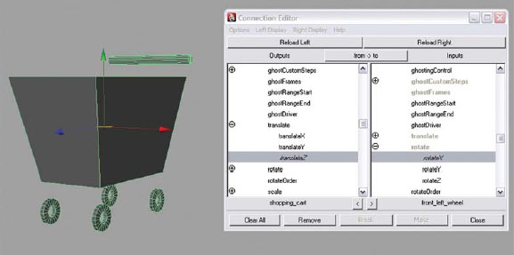
The connection editor can be used to make a direct connection from one attribute to another.
However, this means for every one Maya unit translated in Z, the wheel will rotate only one degree in X. The wheels rotate very slowly with this direct connection. So this is probably not the best way to create this control system. During character setup, the connection editor can be used to connect the NURBS curve controller rotations to the joint or object rotations that they are controlling.

The connection editor can be found in the Window menu under the General Editors submenu.
Expressions [Window > Animation Editors > Expression Editor]
The expression editor also offers the ability to control attributes, but provides even greater control using expressions that contain specific mathematical equations, conditional statements (if, then), or MEL commands. An expression turns the attributes that it controls purple in the channel box.
Returning to our shopping cart example, an expression can be created that gets exactly the same result in a mathematical equation using MEL:
wheel.rotateX = cart.translateZ
However, the great thing here is that we can add more math to make the wheel rotate faster. We can add a multiplier that allows us to increase the speed of the rotation:
wheel.rotateX = cart.translateZ * 45
This equation now rotates the wheel 45 degrees for every Maya unit that the cart is translated.
The above example is just a taste of what can be done with expressions. During character setup, expressions can be used to automate motion, such as a character’s breathing (which will be done in Chapter 8).

The expression editor can use mathematical equations to create attribute control.

The Expression Editor can be found in the Window menu under the Animation Editors submenu.
Set Driven Key [Animate > Set Driven Key > Set…]
Set Driven Key is another tool that creates a control relationship between attributes in a scene file. The difference here is that a range of motion can be established by using keyframes. Set Driven Key is usually used for repetitive motion so that these motions do not need to be animated by hand every time they are needed. Much like the animation process, key poses can be created and keyframed. However, Set Driven Key creates keys which are not dependent on time. Instead, these keys are dependent on the relationship between two attributes. These keys can be manipulated in the Graph Editor. A set driven key turns the attributes that it controls orange in the channel box.
An easy way to think of this relationship is the comparison of a car and a driver. When driving down the street and coming to the corner where the car needs to turn, the driver doesn’t stick his arm out of the window to turn the wheels! Instead, when a driver gets behind the wheel of a car to steer, the driver turns the steering wheel, which then, in turn, is connected to the tire rotation of the car. By turning the steering wheel, the driver can then control the car wheels and their direction.
Set Driven Key works in a similar way. You must first identify the driver (the object that is doing the controlling – also referred to as the driver in Maya), the steering wheel (the specific attribute that will be the controller), the tires (the object, or objects, that are being controlled – referred to as the driven in Maya), and the rotation of the direction of the tires (the specific attribute or attributes being controlled).
During character setup, Set Driven Key is usually used for foot control, finger control, and hand motion.

Set Driven Key can be used to create animated motion linked to other attributes. In the shopping cart example, I have added the ability to steer the front wheels by turning the steering wheel on the Z axis.
When creating Set Driven Keys, it is important to first make sure that your tangents are set in the Preferences to clamped. To do this, go to [Windows > Settings/Preferences > Preferences] click on the Animation category. In the TANGENTS section, choose “clamped” from the dropdown menu for “Default in” and “Default out”.

Set Driven Key can be found in the Animation menu set by pressing (F2) on the keyboard in the Animate menu under the Set Driven Key submenu.
Constraints [Constrain]
Constraints are yet another way to control attributes. One of the benefits of a constraint is that it can be turned off, which proves to be beneficial when creating multiple control options and switching between them. Another benefit is that it can have multiple leaders. A constraint restricts the attributes of one object (follower) to the attributes of another (leader). A constraint turns the attributes that it controls blue in the channel box. If a keyframe is set on the object constrained, the channels will turn green, and the constraint will no longer work. For this reason, group nodes (discussed in the next section) are used to hold the constraint.
There are several different constraints available, but only the following will be used in setup of the character controls.

Constraints can be found in the Animation menu set by pressing (F2) on the keyboard under the Constrain menu.
Point [Constrain > Point]
A point constraint constrains the translation values of an object (follower) to another object (leader). Once the constraint is applied, the pivot of the follower will move to the exact position as the pivot of the leader. To avoid any repositioning, open the option box and choose “maintain offset” before applying the constraint. Once the constraint has been applied, when the leader is moved, then the follower moves also. During character setup, point constraints are often used to control IK handles.
Orient [Constrain > Orient]
An orient constraint constrains the rotation values of an object (follower) to another object (leader). Once the constraint is applied, the rotation of the follower will match to the current rotation values of the leader. To avoid any repositioning, either freeze transformations on both leader and follower, or open the option box and choose “maintain offset” before applying the constraint. Once the constraint has been applied, when the leader is rotated, then the follower rotates along its local axis also. During character setup, orient constraints are often used with a multiple joint chain control system to control joint rotations during the FK/IK switch (this will be explored in the assignments for the arm control rig). Orient constraints can also be used to control the rotations of joints using NURBS curves (leader) and joints (follower).
Parent [Constrain > Parent]
A parent constraint constrains both the translation and rotation values of an object (follower) to another object (leader). The rotational axis for a parent constraint is based on the world axis, not the local axis as with the orient constraint. Because of this, the follower acts as if it were a child to the leader, without actually being part of the hierarchy. Multiple leaders provide the workability of providing multiple parents, which is impossible in a true parent–child relationship. The ability to turn the constraint off provides the keyframing option of “unparenting” during the animation process, which is also impossible in a true parent–child relationship. “Maintain offset” is on by default for this constraint.
During character setup, parent constraints are often used to create parenting relationships that need to be switched during animation (such as having the ability to choose whether the hands follow the body during movement, or stay in place to create stickiness). During the animation process, parent constraints are used also for object interactivity (such as when a character picks up something).
Aim [Constrain > Aim]
An aim constraint constrains the rotation values of an object (follower) to translation position of another object (leader) by establishing an aim vector in the options. To avoid any flipping of the object during the constraining process, open the option box and choose “maintain offset” before applying the constraint. Once the constraint has been applied, when the leader is translated, then the follower rotates along its local axis in order to follow the leader’s position. During character setup, aim constraints are often used for creating eye control.
Pole Vector [Constrain > Pole Vector]
A pole vector constraint constrains the pole vector values of an RP IK solver (follower) to the translation position of another object, or controller (leader). Once the constraint has been applied, when the leader is translated, then the follower will rotate the joint chain through which the IK solver is running. This makes the control of the IK solver interactive and intuitive. During character setup, a pole vector constraint is used only with an RP IK solver.
Geometry [Constrain > Geometry]
A geometry constraint constrains the translation position of an object (follower) to a NURBS surface, NURBS curve, or polygonal surface (leader). It does not lock the translation values of the follower, as other constrains do, so this allows the ability to add a point constraint to follow another leader. Once the constraint has been applied, when the follower is translated, then the follower slides across the geometry (leader). During character setup, geometry constraints can be used with normal constraints for creating eye control for eyes that have separate pupils.
Normal [Constrain > Normal]
A normal constraint constrains the rotation, or orientation, of an object (follower) to a NURBS surface or polygonal surface (leader). Once the constraint has been applied, when the follower is translated, then the follower rotates with the alignment of the normal vectors of the surface geometry (leader). During character setup, normal constraints are used most effectively with geometry constraints for objects that need to slide across a surface, such as pupils that slide across a non-spherical eyeball, or a teardrop rolling down the cheek.
Group Nodes or Null [Edit > Group]
A group node in Maya is a transform node that becomes the parent of the items grouped. It allows you to move, scale, or rotate multiple objects at the same time. However, it can be used for much more.
When we think of a group, we usually think about a collection of items or people, such as a group of desks or a group of children. In Maya, however, a group can be multiple objects, one object, or nothing at all. I like to think of a group node as an invisible box. The “box” can be empty, contain one item, or multiple items. When animating, the “box” can be animated, and the items inside will move along with it. The objects inside the “box” can be animated as well while inside the “box” itself.

An empty group, a group of one object, or a group of several objects as seen in the Hypergraph.
Whenever an object is parented to a joint, group nodes provide a buffer transform node between the joint and the object. Joints, by nature, always contain transform information so that Maya knows where they are positioned in 3D space. When an object is parented to a joint, the object inherits this transform information. This can be a problem, especially when you want to keep transform information frozen on the object. By placing a group node above the object before parenting at the joint, the group node inherits the information from the joint instead of the object. This is especially important when parenting with NURBS curve controllers to joints. By keeping translation and rotation attributes at zero, it is easy to position the character back where they started in the T-pose.
Whenever constraints are used, group nodes provide the ability to continue animating the object constrained. Usually, the constraint is placed on the group node, which is made as the parent of the object being constrained. This way the object itself does not have any of the translation or rotation channels locked, and can still be animated.
If a mistake has been made while setting up attribute controls, simply click on the word of the attribute in the channel box, hold down the RMB (right mouse button) and choose “break connections”. This will remove the link between the attribute controller and the attribute.
Clusters [Create Deformers > Clusters]
A cluster deformer provides the ability to control individual or groups of points (CVs, vertices, or lattice points). By creating the cluster node, it is then possible to create a more intuitive control system. During character setup, clusters are usually used to control the NURBS spline curve that runs through the identified joint chain for the Spline IK.

Clusters can be found in the Animation menu set by pressing (F2) on the keyboard in the Create Deformers menu.
Former Student Spotlight: Ben Willis
Short films are stories: Stories about characters: Characters that have wants, desires, needs, emotions.
You are a storyteller. Even as a rigger, you are a storyteller. You define limitations. You define boundaries. But with boundaries there is freedom for expression.
Whether skinning or modeling, take your time to build the character right. Understand what the character needs. If you take the time now, you will see the freedom it will allow you later on, and how much better your short film will be.
The greatest piece of advice I could ever think to give a first time short film maker is keep things simple. Find that one idea with the most potential for expression in a short amount of time and dedicate all your efforts to that endeavor. Give yourself the best opportunity to see a project from conception to completion. There will always be time to be more ambitious. You WILL make mistakes. Nothing will ever turn out exactly as you intended. But in those “flaws” comes the beauty of making a film. You will learn and you will grow.
Ben Willis graduated from the Savannah College of Art and Design with a BFA in Animation. His first professional project after graduation was working at Charlex as an animator on a short film entitled “One Rat Short”, which won Best in Show and People’s Choice at SIGGRAPH ’06 Electronic Theater. He currently works for Dreamworks Animation as an animator. You can see more of his work on his website: www.benjaminwillis.net.

Ping by Ben Willis (2004).
6.1 The purpose of a control rig is to simplify the animation process, making it easier for animators to pose their characters in a 3D environment.
6.2 Animation, by definition, is the ability to bring something to life through movement.
6.3 Kinematics is the study of motion.
6.4 FK is a method where a hierarchy of joints or objects is rotated into a position and keyframed at every point of the hierarchy.
6.5 IK is a mathematical system that calculates the rotations of joints in a predefined chain.
6.6 When animating, IK provide the ability for stickiness.
6.7 Maya has three different IK solvers: the SC solver, the RP solver, and the spline solver.
6.8 Since IK solvers have a tendency to break and stop solving, a control system is used so that keyframes are not lost during animation.
6.9 It is common to create multiple control chains for different areas of the body for maximum control.
6.10 Maya uses an Euler rotation method when calculating the rotations of joints during an animation. When evaluating a joints rotation from one position to the next, the rotations are considered by a specific order dependent on the X, Y, or Z axis.
6.11 Gimbal lock occurs when two of the joint axes align during a rotation causing the inability to rotate in a particular direction.
6.12 It is important to animate in Gimbal mode so that you know exactly what type of rotations are occurring.
6.13 The connection editor is a tool that allows you to create a direct connection from one attribute to another.
6.14 The expression editor provides a place where MEL programming language can be used to create mathematical expressions within the scene environment.
6.15 Set Driven Key is a powerful tool unique to Maya that provides attribute control using keyframes set on one or more attributes as they relate to the value of the attribute in control.
6.16 Constraints are a leader and follower relationship, where one object’s attribute leads while another object’s attributes follows. Constraints can be keyframed on and off.
6.17 A point constraint controls the translation values of an object.
6.18 An orient constraint controls the rotation values of an object.
6.19 A parent constraint controls both the translation and rotation values based on the world axis.
6.20 An aim constraint controls the rotational values of an object and points them toward another object using an aim vector.
6.21 A pole vector constraint controls the pole vector values of an RP IK solver.
6.22 A geometry constraint constrains the translation position of an object to the surface of another.
6.23 A normal constraint constrains the rotation orientation of an object to the surface of another.
6.24 A group node is an empty transform node, or a transform node above one or more objects in a hierarchy. Think about group nodes as invisible boxes that can be empty or have one or more objects inside.
6.25 Group nodes can be placed above any object when constraints are used.
6.26 Clusters are deformers that provide the ability to control CVs or vertices. In character setup, they are used to help control the Spline IK solver.
Assignment 6.1: Creating a Control System for the Spine Skeleton
Most of the controllers used in these assignments are made from the NURBS circle. In the companion DVD, I have provided some different shapes that can be used instead. If you would like to use the control shapes that I have provided, simply go to [File > Import] and find the Maya file on the DVD to import it into your scene file.
Set up your work environment by doing the following:
1. Open Maya and set your project.
• From your computer’s desktop, go to [Start > Programs] and select Maya.
• Once Maya is open go to [File > Project > Set…] and browse to your project folder then click OK.
2. Open your last saved file: Go to [File > Open] and select 05_asgn05.ma.
3. Continue working in X-ray Joints mode.
4. Make sure that your geometry is placed on a layer and that the layer is set to R for reference so that you are unable to select the geometry by mistake when working.
5. To make selection easier, open your outliner by going to [Windows > Outliner]. (In order to control the spine and still keep it flexible and natural looking, we will create an FK chain that controls an IK chain.)
6. Create an FK joint chain and an IK joint chain for the spine by doing the following:
• Select the spine1 joint.
• Rename the original chain by adding the IK_prefix. Select [Modify > Prefix Hierarchy Names…] and set the following:
i. Enter prefix: “IK_”.
ii. Click OK.
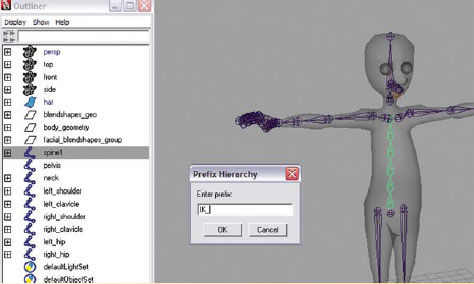
Adding the IK prefix to the spine joint chain.
• Duplicate the IK chain by going to [Edit > Duplicate] or press (ctrl+d). (The duplicated joint chain begins with IK_spine7. Since there already is an IK_spine1 joint that begins the original joint chain, Maya places the next number as to not label with the same joint name. Having two IK_spine1 joint chains would cause confusion in Maya. Maya will not use the exact name for multiple nodes. However, be careful NOT to use the exact name for multiple nodes when the nodes are in different hierarchies.)
• Select the IK_spine7 joint chain and rename the hierarchy by going to [Modify > Search and Replace Names…] and set the following:
i. Search for: “IK”.
ii. Replace with: “FK”.

Renaming the duplicated IK chain as an FK chain using search and replace.
• Select FK_spine7 and in the channel box, rename it to FK_spine1.
You should now have two joint chains for the spine – one FK chain (beginning with FK_spine1) and one IK chain (beginning with IK_spine1).
7. We will now create the FK spine first. Remember, the FK spine should be created first so that the correct rotational orders can be set. It is very helpful to HIDE the IK_spine1 joint chain so that it does not get in the way while creating the FK controls.
![]()
To hide something in Maya, select the object and press (ctrl+h). You will notice that it turns blue in the OUTLINER. To make it visible again, select the object in the OUTLINER and press (shift + h).
8. In the OUTLINER, select the IK_spine1 joint chain and press (ctrl+h) to hide the chain.
9. For the FK chain, we will not need all six joints – four should be plenty. We can remove the extra joints from the FK chain one at a time:
• Select the FK_spine2.
• Go to [Skeleton > Remove Joint].
• Select the FK_spine5.
• Press the (g) key to repeat the last command of removing a joint.

Removing extra joints in the FK spine.
10. Select the move tool by pressing (w), press the (insert) key on the keyboard, and reposition the FK_spine3 joint on so that it is level at the waist of your character. Reposition the FK_spine4 joint (up or down) so that it is level at the base of where your character’s rib cage would be located.

Repositioning the FK spine joints.
11. Create a NURBS control for the upper body by doing the following:
• Go to [Create > EP Curve Tool – option box].
• Under EP Curve Settings, change the following:
Curve degree: choose “1 linear”.
• In the top view, use the grid snap tool by holding the (x) key and click to draw a square around the body of your character. Hit “enter” when completed.
• In the channel box, rename the square upperBody_ctrl.

Creating the upperBody_ctrl.
• In PERSPECTIVE view, select the move tool by pressing (w), hold down the (v) key, position your cursor over the FK_spine1 joint, and click the MMB (middle mouse button) and drag it slightly to snap the upperBody_ctrl into place. (This is an easy way to ensure that the pivot of the square is snapped precisely in place. It might not seem easy at first, but after you have done this a few times, it will be easy. The important thing to remember is to place your mouse cursor over the joint that you want the controller to control. Do not click on the move tool when using the snap key.)
• Use the scale tool by pressing (r) and resize the square if necessary. (This control should be scaled large enough that it is far OUTSIDE of the character’s geometry to make it easy to select.)
• With the upperBody_ctrl selected, go to [Modify > Freeze Transformations]. (To return the translate values to 0 and the scale values to 1.)
• In the OUTLINER, hold down the MMB, click on the FK_Spine1 joint and drag it onto the upperBody_ctrl. (This makes the FK_Spine1 child to the upperBody_ctrl. By moving or rotating this controller, the entire Upper Body will move with it.)
• Change the rotation order for the upperBody_ctrl by doing the following:
i. With the upperBody_ctrl selected, open the attribute editor by pressing (ctrl+a).
ii. Select the upperBody_ctrl tab.
iii. Under Transform Attributes set the following:
1. Rotate order: choose “ZXY”.

Parenting the FK_spine1 to the upperBody_ctrl, then changing the rotate order to ZXY.
12. Create controls for the FK spine by doing the following:
• First, we must reorient the FK spine by selecting the FK_spine1 joint and going to [Skeleton > Orient Joint – option box]. Set the following:
i. Orientation: choose “YZX”.
ii. Second axis world orientation: choose +Z.
(This will ensure that the joint orientation aligns with the world axis, which is necessary for FK control.)
iii. Click Orient.

Reorienting the FK_spine1 joint chain.
• Go to [Create > NURBS Primitives > Circle].
• In the MEL command line, type the MEL script below:
parent -add -shape nurbsCircleShape1 FK_spine3;
(This command gives a NURBS shape to the joint, making it easier to select during animation. It will appear that there are two NURBS circles in the scene.)
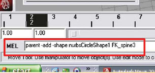
Typing a MEL script in the MEL command line.
• Resize the circle to fit around your character’s geometry by doing the following:
i. Press the (F8) key.
ii. Choose the “select point components” button in the Status Line.
iii. Using the scale tool by pressing (r), click and drag around the points of the circle and scale them larger so that it extends beyond the character’s body to make it easier to select when animating. (This affects both circles visible.)

Scaling the nurbsCircleShape1 to fit around the character’s geometry.
• Press the (F8) key to go back into object mode.
• Select the FK_spine3 joint, and in the channel box, rename FK_spine3 to lower_spine_ctrl.
• Change the rotation order for the lower_spine_ctrl by doing the following:
i. With the lower_spine_ctrl selected, open the attribute editor by pressing (ctrl+a).
ii. Select the lower_spine_ctrl tab.
iii. Under Transform Attributes set the following:
1. Rotate order: choose “ZXY”.
• In the OUTLINER, go to [Display] and make sure there is a check mark next to shapes. If not, click on the word shapes.

Displaying the shapes in the OUTLINER.
• In the OUTLINER, hold down the shift key and click on the plus sign ( + ) next to the upperBody_ctrl to open the hierarchy and display the children.
• Double-click on nurbsCircleShape1 and rename it LowerSpineShape. (We must rename the nurbsCircleShape1 so that Maya does not get confused if we create more NURBS circles later.)
![]()
Feel free to turn the shape option off again later, as displaying shapes can clutter up the OUTLINER and make it confusing when trying to find objects. Just remember to turn it back on when necessary to select shapes.

Renaming the nurbsCircleShape1 to LowerSpineShape.
• In the OUTLINER, select nurbsCircle1 hit the delete key. (We no longer need the NURBS curves – we only needed the shape node.)
13. Repeat this process for the next joint in the spine by doing the following:
• Go to [Create > NURBS Primitives > Circle].
• In the MEL command line, type the MEL script below:
parent -add -shape nurbsCircleShape1 FK_spine4;
• Resize the circle to fit around your character’s geometry by doing the following:
i. Press the (F8) key to go into component mode.
ii. Choose the “select point components” button in the Status Line.
iii. Using the scale tool by pressing (r), click and drag around the points of the new circle and scale them larger so that it extends beyond the character’s body to make it easier to select when animating.
• Press the (F8) key to go back into object mode.
• Select the FK_spine4 joint, and in the channel box, rename FK_spine4 to upper_spine_ctrl.
• Change the rotation order for the upper_spine_ctrl by doing the following:
i. With the upper_spine_ctrl selected, open the attribute editor by pressing (ctrl+a).
ii. Select the upper_spine_ctrl tab.
iii. Under Transform Attributes set the following:
1. Rotate order: choose “ZXY”.
• Double-click on nurbsCircleShape1 and rename it UpperSpineShape. (We must rename the nurbsCircleShape1 so that Maya does not get confused if we create more NURBS circles later.)
• In the OUTLINER, select nurbsCircle1 hit the delete key.
14. Now that we are finished with the FK spine, we can hide it to work on the IK spine. In the OUTLINER, select the upperBody_ctrl and press (ctrl+h) to hide it.
15. In the OUTLINER, select the IK_spine1 joint chain and press (shift + h) to display the chain.
16. Create the IK spine by doing the following:
• Go to [Skeleton > IK Spline Handle Tool – option box] and click “reset tool” then click close.
• In the PERSPECTIVE window, click on the IK_spine1 joint (the bottom spine IK joint) to define the start of the IK joint chain then click on the IK_spine6 joint (the top spine IK joint) to define the end of the chain. (An IK handle appears at the end of the chain.)

Creating the spine ikHandle.
• A Spline IK system is created with a curve running through the selected joints. You can then control this joint system by selecting the CVs of this curve and moving them. It is awkward, however, to select individual CVs (as CVs can only be selected in component mode) and keyframe them (as CVs only have positions not based on the X, Y, and Z coordinates). We will create cluster deformers on each CV to make them easier to select, move, and keyframe on the X, Y, and Z coordinate systems.
![]()
As you place an IK handle, you can adjust the display size to see it better by doing the following:
Select [Display > Animation > IK Handle Sizes…].
Adjust the slider so that the IK handle is an appropriate size.
• In the OUTLINER, double-click on ikHandle1 and rename it spine_ikHandle.
• In the OUTLINER, double-click on curve1 and rename it spine_curve. (Curve1 is the spline curve that controls the IK solver.)
17. Create a control system for the IK spine by doing the following:
• In the PERSPECTIVE view panel, go to [Show > None], then [Show > Curves] and [Show > Deformers].
• In the OUTLINER, select the spine_curve.
• Change to component mode by pressing (F8). Make sure that the “select point components” button is depressed in the Status Line.
• Select the top CV point by click dragging across the spine to first display the CVs, then click dragging around the top CV point.

Selecting a CV on the spine_curve.
• Select [Create Deformers > Cluster]. (A green highlighted “C” will appear at the top of your FK spine joint chain. If it is not at the top, it usually indicates that more than one CV was selected. If this is your situation, simply undo by pressing (z) and reselecting only the top point.)
• Select the next point on the curve. Remember, if you are having trouble seeing it, first select the curve by click dragging across the spine to first display the CVs, then click dragging around the second CV point from the top.
• With the second CV selected, press the (g) key to repeat the last command of [Create Deformers > Cluster].
• Repeat this process for the third and fourth CV points.
• In the OUTLINER, double-click on cluster1handle and rename it spine_cluster1handle.
• In the OUTLINER, double-click on cluster2handle and rename it spine_cluster2handle.
• In the OUTLINER, double-click on cluster3handle and rename it spine_cluster3handle.
• In the OUTLINER, double-click on cluster4handle and rename it spine_cluster4handle.

Creating the clusters on the spine_curve.
• In the PERSPECTIVE view panel, go to [Show > All].
![]()
It is still difficult to select clusters. To make control of the clusters easier, we will parent them to NURBS controllers.
• Go to [Create > NURBS Primitives > Circle].
• In the channel box, rename the circle spine_shoulder_ctrl.
Set the RotateZ channel to “90”.
• In PERSPECTIVE view, select the move tool by pressing (w), hold down the (v) key, position your cursor over the IK_spine6 joint, and click the MMB and drag it slightly to snap the spine_shoulder_ctrl into place.
• Use the scale tool by pressing (r) and resize the circle if necessary. (This control should be scaled large enough that it is far OUTSIDE of the character’s geometry to make it easy to select.)
• With the spine_shoulder_ctrl selected, go to [Modify > Freeze Transformations]. (To return both translate and rotate values to 0 and the scale values to 1.)

Creating the spine_shoulder_ctrl.
• Go to [Create > NURBS Primitives > Circle].
• In the channel box, rename the circle hip_ctrl.
• In PERSPECTIVE view, select the move tool by pressing (w), hold down the (v) key, position your cursor over the pelvis joint, and click the MMB and drag it slightly to snap the hip_ctrl into place.
• Use the scale tool by pressing (r) and resize the circle if necessary. (This control should be scaled large enough that it is OUTSIDE of the character’s geometry to make it easy to select.)
• With the hip_ctrl selected, go to [Modify > Freeze Transformations]. (To return both translate and rotate values to 0 and the scale values to 1.)

Creating the hip_ctrl.
• In the OUTLINER, click on the spine_cluster1handle cluster; then holding down the ctrl key, click on the spine_cluster2handle cluster and the spine_shoulder_ctrl. Press the (p) key to parent them. (This makes the spine_cluster1handle and spine_cluster2handle child to the spine_shoulder_ctrl. When you parent the clusters, they are automatically grouped. Maya displays a warning for notification, and is nothing to worry about.)
• In the OUTLINER, click on the spine_cluster3handle cluster; then holding down the ctrl key, click on the spine_cluster4handle cluster and the hip_ctrl. Press the (p) key to parent them. (This makes the spine_cluster3handle and spine_cluster4handle child to the hip_ctrl.)

Parenting the clusters to the the spine_shoulder_ctrl and hip_ctrl.
• (When spine_ikHandle is selected, notice that there is an attribute named Twist. If you click on the word Twist in the channel box, place your cursor over the PERSPECTIVE view panel, and MMB click and drag left to right, you will notice that the joint rotation is tapered down to the beginning of the IK chain at the IK_spine1 joint. We can control this Twist attribute interactively with the Advanced Twist options in the attribute editor to provide natural left to right rotation of the spine when the shoulders rotate.)

Notice the wireframe of the skinned character on the left as compared to the character on the right. The character on the left is simply rotating the top of the spine, while the character on the right shows how the twist attribute creates natural rotations down the spine when the character turns from right to left.
• Select the spine_ikHandle and press (ctrl+a) to open attribute editor.
• Scroll down to the IK Solver Attributes and click on the arrow (>) to open the section.
• Scroll down to the Advanced Twist Controls and click on the arrow (>) to open the section.
• Under Advanced Twist Controls section, put a check next to “Enable Twist Controls” and set the following:
World Up Type: choose “Object Rotation Up (Start/End)”.
Up Axis: choose “Negative Z”.
Up Vector: type “0” “0” “–1”.
Up Vector 2: type “0” “0” “–1”.
World Up Object: type “hip_ctrl”.
World Up Object 2: type “spine_shoulder_ctrl”.
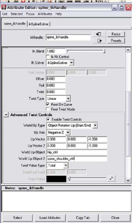
Setting the Advanced Twist Controls.
• Change the rotation order for the hip_ctrl by doing the following:
i. With the hip_ctrl selected, open the attribute editor by pressing (ctrl+a).
ii. Select the hip_ctrl tab.
iii. Under Transform Attributes set the following:
1. rotate order: choose “ZXY”.
• Change the rotation order for the spine_shoulder_ctrl by doing the following:
i. With the spine_spine_shoulder_ctrl selected, open the attribute editor by pressing (ctrl+a).
ii. Select the spine_spine_shoulder_ctrl tab.
iii. Under Transform Attributes set the following:
1. Rotate order: choose “ZXY”.
18. Integrate the IK spine into the existing spine controls by doing the following:
• In the OUTLINER, select the upperBody_ctrl and press (shift + h) to display it.
• In the OUTLINER, hold down the shift key and click on the plus sign ( + ) next to the upperBody_ctrl to open the hierarchy and display the children.
• Select the spine_shoulder_ctrl and press (ctrl+g) to group the spine_shoulder_ctrl node. (We must group the spine_shoulder_ctrl to add a buffer between the joint and the controller as discussed earlier in this chapter.)
• In the OUTLINER, double-click on the group node and rename it spine_shoulder_ctrl_pad.
• In the OUTLINER, hold down the MMB, click on the spine_shoulder_ctrl_pad and drag it onto the FK_spine6 joint. (This makes the spine_shoulder_ctrl_pad child to the FK_spine6 joint.)
• In the OUTLINER, hold down the MMB, click on the hip_ctrl and drag it onto the upperBody_ctrl. (No group is necessary when the parent is a NURBS curve.)

Integrating the IK spine into the FK spine.
19. Save your scene file. Name your scene 06_asgn01.ma.
Assignment 6.2: Creating a Control System for the Neck and Head Skeleton
1. Open Maya and set your project.
a. From your computer’s desktop, go to [Start > Programs] and select Maya.
b. Once Maya is open go to [File > Project > Set…] and browse to your project folder then click “OK”.
2. Open your last saved file: Go to [File > Open] and select 06_asgn01.ma.
3. Continue working in X-ray mode.
4. Make sure that your geometry layer is set to R for reference so that you are unable to select the geometry by mistake when working.
5. To make selection easier, open your OUTLINER by going to [Windows > Outliner].
6. First, we must reorient the neck for FK control by
a. Select the neck joint and go to [Skeleton > Orient Joint – option box]. Set the following:
i. Orientation: choose “YZX”.
ii. Second axis world orientation: choose +Z.
(This will ensure that the joint orientation aligns with the world axis.)
iii. Click orient.
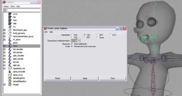
Reorienting the neck joint chain.
b. Go to [Create > NURBS Primitives > Circle].
c. In the MEL command line, type the MEL script below:
parent -add -shape nurbsCircleShape1 neck;
(This command gives a NURBS shape to the joint, making it easier to select during animation. It will appear that there are two NURBS circles in the scene.)
d. Resize the circle to fit around your character’s neck geometry by doing the following:
i. Press the (F8) key.
ii. Choose the “select point components” button in the Status Line.
iii. Using the scale tool by pressing (r), click and drag around the points of the circle and scale them larger so that it extends beyond the character’s neck to make it easier to select when animating. (This affects both circles visible.)
e. Press the (F8) key to go back into object mode.
f. Select the neck joint, and in the channel box, rename neck to neck_ctrl.
g. Change the rotation order for the neck_ctrl by doing the following:
i. With the neck_ctrl selected, open the attribute editor by pressing (ctrl+a).
ii. Under Transform Attributes set the following:
1. Rotate order: choose “ZXY”.

Adding a nurbsCircleShape1 to the neck joint.
h. In the OUTLINER, go to [Display] and make sure there is a check mark next to shapes. If not, click on the word shapes.
i. In the OUTLINER, hold down the shift key and click on the plus sign ( + ) next to the neck_ctrl to open the hierarchy and display the children.
j. Double-click on nurbsCircleShape1 and rename it neckShape. (We must rename the nurbsCircleShape1 so that Maya does not get confused if we create more NURBS circles later.)
k. In the OUTLINER, select nurbsCircle1 and hit the delete key. (We no longer need the NURBS curves – we only needed the shape node.)

Finding the nurbsCircleShape1 in the OUTLINER.
7. Repeat this process for the head joint by doing the following:
a. Go to [Create > NURBS Primitives > Circle].
b. In the MEL command line, type the MEL script below:
parent -add -shape nurbsCircleShape1 head;
c. Resize the circle to fit around your character’s head geometry by doing the following:
i. Press the (F8) key to go into component mode.
ii. Choose the “select point components” button in the Status Line.
iii. Using the scale tool by pressing (r), click and drag around the points of the new circle and scale them larger so that it extends beyond the character’s head to make it easier to select when animating. (Some students like using the move tool by pressing (w) and moving the points up around the forehead area, like a head band, because the area around the neck is starting to get a bit congested with controllers – or you could rotate the points into a different direction, like in the image below.)
d. Press the (F8) key to go back into object mode.
e. Select the head joint, and in the channel box, rename head to head_ctrl.
f. Change the rotation order for the head_ctrl by doing the following:
i. With the head_ctrl selected, open the attribute editor by pressing (ctrl+a).
ii. Under Transform Attributes set the following:
1. Rotate order: choose “ZXY”.

Adding a nurbsCircleShape1 to the head joint.
g. In the OUTLINER, select nurbsCircle1 and hit the delete key.
h. Double-click on nurbsCircleShape1 and rename it headShape.
8. Integrate the neck and head into the existing spine controls by doing the following:
a. In the PERSPECTIVE window, select the neck_ctrl, hold down the (shift) key and click the shoulder_spine_ctrl, and press (p) to parent.
9. Save your scene file. Name your scene 06_asgn02.ma.
Assignment 6.3: Creating a Control System for the Clavicle
1. Open Maya and set your project.
a. From your computer’s desktop, go to [Start > Programs] and select Maya.
b. Once Maya is open go to [File > Project > Set…] and browse to your project folder then click “OK”.
2. Open your last saved file: Go to [File > Open] and select 06_asgn02.ma.
3. Continue working in X-ray mode.
4. Make sure that your geometry layer is set to R for reference so that you are unable to select the geometry by mistake when working.
5. To make selection easier, open your OUTLINER by going to [Windows > Outliner].
6. In the OUTLINER, select the left_shoulder joint chain and the right_shoulder joint chain – then press (ctrl+h) to hide the chain so that it is not in the way as we set up the arm.
7. Create the IK clavicle by doing the following:
a. Go to [Skeleton > IK Handle Tool – option box] and set the following:
i. Click “reset tool” then under IK Handle Settings change the following:
Current solver: choose “ikSCsolver”.
Place a check mark in the box next to Sticky.
Then click “close”.
b. In the PERSPECTIVE window, click on the left_clavicle joint (to define the start of the IK joint chain) then click on the left_clavicleTip joint (to define the end of the chain. An IK handle appears at the end of the chain).
c. In the OUTLINER, double-click on ikHandle1 and rename it leftClavicle_ikHandle. (This chain will control the clavicle movement.)
d. Repeat for the right clavicle.

Creating the Clavicle_ikHandles.
8. Create a control system for the IK clavicle by doing the following:
a. First create the controllers by doing the following:
i. Go to [Create > EP Curve Tool – option box]
1. Under EP Curve Settings, change the following:
Curve degree: choose “1 linear”.
ii. In the FRONT view, use the grid snap tool by holding the (x) key and click to draw an arrow around the shoulder of your character. Hit “enter” when completed.

Drawing an arrow shaped curve using the EP curve tool.
iii. In the channel box, rename the arrow left_clavicle_ctrl.
iv. With the left_clavicle_ctrl selected go to [Modify > Center Pivot].
v. In PERSPECTIVE view, select the move tool by pressing (w), hold down the (v) key, position your cursor over the left_clavicleTip joint, and click the MMB and drag it slightly to snap the left_clavicle_ctrl into place.
vi. Move and scale the arrow by doing the following:
1. Press the (F8) key.
2. Choose the “select point components” button in the Status Line.
vii. Using the scale tool by pressing (r), click and drag around the points of the arrow and scale them. This control should be scaled large enough that it is ABOVE the character’s shoulder to make it easy to select when animating. Use the rotate tool by pressing (e) and rotate the arrow slightly away from the neck.
viii. With the left_clavicle_ctrl selected, go to [Modify > Freeze Transformations]. (To return both translate and rotate values to 0 and the scale values to 1.)

Positioning the left_clavicle_ctrl.
ix. Duplicate the left_clavicle_ctrl by going to [Edit > Duplicate] or press (ctrl+d).
x. In the OUTLINER, double-click on left_clavicle_ctrl1 and rename it right_clavicle_ctrl.
ix. In PERSPECTIVE view, select the move tool by pressing (w), click on the X axis (red arrow), hold down the (v) key, position your cursor over the right_clavicleTip joint, and click the MMB and drag it slightly to snap the right_clavicle_ctrl into place.
xii. With the right_clavicle_ctrl selected set the following in the channel box: RotateY: type “180”.

Duplicating the arrow and positioning the left_clavicle_ctrl.
xiii. Use the scale tool by pressing (r) and resize the arrow if necessary. With the right_clavicle_ctrl selected, go to [Modify > Freeze Transformations]. (To return both translate and rotate values to 0 and the scale values to 1.)
xiv. UThe rotation order does not need to be changed on this controller, because rotations are not necessary for control.
10. Create control between the controllers and the IK handles by doing the following:
a. In the OUTLINER, click on the leftClavicle_ikHandle with the MMB and drag it onto the left_clavicle_ctrl. (This makes the leftClavicle_ikHandle child to the left_clavicle_ctrl.)
b. In the OUTLINER, click on the rightClavicle_ikHandle with the MMB and drag it onto the right_clavicle_ctrl. (This makes the rightClavicle_ikHandle child to the right_clavicle_ctrl.)
11. Integrate the clavicles into the existing spine controls by doing the following:
a. In the PERSPECTIVE window, select the left_clavicle joint, hold down the (shift) key and click the right_clavicle joint, the left_clavicle_ctrl, the right_ clavicle_ctrl, the shoulder_spine_ctrl, and then press (p) to parent.

The new OUTLINER hierarchy after integrating the clavicles into the existing spine controls.
12. In the OUTLINER, select the left_shoulder joint chain and right_shoulder joint chain and press (shift + h) to display them.
13. Save your scene file. Name your scene 06_asgn03.ma.
Assignment 6.4: Creating a Control System for the Arm
1. Open Maya and set your project.
a. From your computer’s desktop, go to [Start > Programs] and select Maya.
b. Once Maya is open go to [File > Project > Set…] and browse to your project folder then click “OK”.
2. Open your last saved file: Go to [File > Open] and select 06_asgn03.ma.
3. Continue working in X-ray mode.
4. Make sure that your geometry layer is set to R for reference so that you are unable to select the geometry by mistake when working.
5. To make selection easier open your OUTLINER by going to [Windows > Outliner].
6. In the OUTLINER, select the upperBody_ctrl and press (ctrl+h) to hide the chain, so that it is not in the way as we set up the arm.
We will be creating 3 joint chains for the arm. One chain will control the geometry, and two chains will have control systems – one for FK and one for IK. A switch will be implemented for the chain that controls the geometry so that the animator can choose which control system it will follow.
7. Create an FK joint chain for the arm by doing the following:
a. Select the left_shoulder joint.
b. Duplicate it by going to [Edit > Duplicate] or press (ctrl+d).
8. Add FK_ prefix to duplicated chain by selecting [Modify > Prefix Hierarchy Names…] and set the following:
a. Enter prefix: “FK_”.
b. Click OK.
(The duplicated joint chain now begins with the FK_left_shoulder1.)
9. In the OUTLINER, double-click on FK_left_shoulder1 and remove the 1, renaming it to FK_left_shoulder.
10. In the OUTLINER, hold down the shift key and click on the plus sign ( + ) next to the FK_left_shoulder to open the hierarchy and display the children.

The new FK_left_shoulder hierarchy as seen in the OUTLINER.
11. For the FK chain, we will not need the FK_left_forearm joint. We can remove the extra joint from the chain by doing the following:
a. Select the FK_left_shoulder joint.
b. Go to [Skeleton > Remove Joint].
12. In the OUTLINER, hold down the shift key and click on the plus sign ( + ) next to the FK_left_wrist to open the hierarchy and display the children.
13. For the FK chain, we will not need the finger joints. We can remove the extra joints from the chain by doing the following in the OUTLINER:
a. Select the FK_left_middle1 joint and hit the (delete) key on the keyboard.
b. Select the FK_left_ring1 joint and hit the (delete) key on the keyboard.
c. Select the FK_left_index1 joint and hit the (delete) key on the keyboard.
d. Select the FK_left_pinkyPalm joint and hit the (delete) key on the keyboard.
e. Select the FK_left_thumbPalm joint and hit the (delete) key on the keyboard.
Your joint chain should be left with only four joints:
FK_left_shoulder, FK_left_elbow, FK_left_wrist, and FK_left_palm.

The FK_left_shoulder hierarchy after removing the unnecessary joints.
14. Create an IK joint chain for the arm by doing the following:
a. Select the FK_left_shoulder joint.
b. Duplicate it by going to [Edit > Duplicate] or press (ctrl+d).
15. Select the FK_left_shoulder1 joint and rename the hierarchy by going to [Modify > Search and Replace Names…] and set the following:
a. Search for: “FK”.
b. Replace with: “IK”.
(The duplicated joint chain now begins with the IK_left_shoulder1.)
16. In the OUTLINER, double-click on IK_left_shoulder1 and remove the 1, renaming it to IK_left_shoulder.

The new IK_left_shoulder hierarchy as seen in the OUTLINER.
17. At this time, we can mirror this chain for the right side by doing the following:
a. Select the IK_left_shoulder joint, then go to [Skeleton > Mirror Joint – option box] and enter the following:
Mirror Across: choose “YZ” axis.
Mirror Function: choose “behavior”.
Replacement names for duplicated joints:
Search for: enter “left”.
Replace with: enter “right”.
Then click “mirror” to execute the command. (We will not mirror the FK arm at this time. Instead, we will now create the FK arm controls first and then mirror, saving time, and some repetition.)
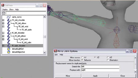
Mirroring the IK_left_shoulder joint for the right arm.
Remember, the FK arm should be created first so that the correct rotational orders can be set. It is very helpful to HIDE the joint chains that you don’t need so that they do not get in the way while creating the FK controls.
18. In the OUTLINER, select the IK_left_shoulder joint chain and the IK_right_shoulder joint chain – then press (ctrl+h) to hide them.
19. In the OUTLINER, select the left_shoulder joint chain and the right_shoulder joint chain – then press (ctrl+h) to hide them.
20. Create controls for the FK arm by doing the following:
a. Go to [Create > NURBS Primitives > Circle].
b. In the MEL command line, type the MEL script below:
parent -add -shape nurbsCircleShape1 FK_left_shoulder;
c. Resize the circle to fit around your character’s upper arm geometry by doing the following:
i. Press the (F8) key.
ii. Choose the “select point components” button in the Status Line.
iii. Using the scale tool by pressing (r), the move tool by pressing (w), and the rotate tool by pressing (e), click and drag around the points of the circle and scale them larger so that it extends beyond the character’s arm. Position it over the upper arm, and rotate to face forward to make it easier to select when animating.
d. Press the (F8) key to go back into object mode.
e. Select the FK_left_shoulder joint, and in the channel box, rename FK_left_shoulder to FK_left_shoulder_ctrl.
f. Change the rotation order for the FK_left_shoulder_ctrl by doing the following:
i. With the FK_left_shoulder_ctrl selected, open the attribute editor by pressing (ctrl+a).
ii. Under Transform Attributes set the following:
1. Rotate order: choose “XZY”.

Adding a nurbsCircleShape1 to the FK_left_shoulder joint.
21. Repeat this process for the elbow joint by doing the following:
a. Go to [Create > NURBS Primitives > Circle].
b. In the MEL command line, type the MEL script below:
parent -add -shape nurbsCircleShape2 FK_left_elbow;
c. Resize the circle to fit around your character’s forearm geometry by doing the following:
i. Press the (F8) key to go into component mode.
ii. Choose the “select point components” button in the Status Line.
iii. Using the scale tool by pressing (r), the move tool by pressing (w), and the rotate tool by pressing (e), click and drag around the points of the circle and scale them larger so that it extends beyond the character’s forearm, position it over the upper arm, and rotate to face forward to make it easier to select when animating.
d. Press the (F8) key to go back into object mode.
e. Select the FK_left_elbow joint, and in the channel box, rename FK_left_elbow to FK_left_elbow_ctrl.
f. Change the rotation order for the FK_left_elbow_ctrl by doing the following:
i. With the FK_left_elbow_ctrl selected, open the attribute editor by pressing (ctrl+a).
ii. Under Transform Attributes set the following:
1. Rotate order: choose “XZY”.

Adding a nurbsCircleShape2 to the FK_left_elbow joint.
22. Repeat this process for the wrist joint by doing the following:
a. Go to [Create > NURBS Primitives > Circle].
b. In the MEL command line, type the MEL script below:
parent -add -shape nurbsCircleShape3 FK_left_wrist;
c. Resize the circle to fit around your character’s hand geometry by doing the following:
i. Press the (F8) key to go into component mode.
ii. Choose the “select point components” button in the Status Line.
iii. Using the scale tool by pressing (r), the move tool by pressing (w), and the rotate tool by pressing (e), click and drag around the points of the circle and scale them larger so that it extends beyond the character’s hand, position it over the upper arm, and rotate to face forward to make it easier to select when animating.
d. Press the (F8) key to go back into object mode.
e. Select the FK_left_wrist joint, and in the channel box, rename FK_left_wrist to FK_left_hand_ctrl.
f. Change the rotation order for the FK_left_hand_ctrl by doing the following:
i. With the FK_left_hand_ctrl selected, open the attribute editor by pressing (ctrl+a).
ii. Under Transform Attributes set the following:
1. Rotate order: choose “ZYX”.

Adding a nurbsCircleShape3 to the FK_left_wrist joint.
g. In the OUTLINER, select nurbsCircle1, nurbsCircle2, and nurbsCircle3 and hit the delete key. (We no longer need the NURBS curves – we only needed their shape nodes.)
h. In the OUTLINER, go to [Display] and make sure there is a check mark next to shapes. If not, click on the word shapes.
i. In the OUTLINER, hold down the shift key and click on the plus sign ( + ) next to the FK_left_spine_shoulder_ctrl to open the hierarchy and display the children.
j. Double-click on nurbsCircleShape1 and rename it leftShoulderShape (we must rename the nurbsCircleShape1 so that Maya does not get confused if we create more NURBS circles later.
k. Double-click on nurbsCircleShape2 and rename it leftElbowShape.
l. Double-click on nurbsCircleShape3 and rename it leftHandShape.
Renaming nurbsCircleShape1, nurbsCircleShape2, nurbsCircleShape3 in the OUTLINER, and deleting the NURBS circle curves.
23. At this time, we can mirror this chain for the right side by doing the following:
a. Select the FK_left_shoulder_ctrl joint, then go to [Skeleton > Mirror Joint – option box] and enter the following:
Mirror Across: choose “YZ” axis.
Mirror Function: choose “behavior”.
Replacement names for duplicated joints:
Search for: enter “left”.
Replace with: enter “right”.
Then click “mirror” to execute the command.

Mirroring the FK_left_shoulder_ctrl for the right arm.
b. When the arm is mirrored, the NURBS shapes do not. We must move them into the correct area of the arm. To do this, select the FK_right_hand_ctrl and reposition the curve by doing the following:
i. Press the (F8) key.
ii. Choose the “select point components” button in the Status Line.
iii. Using the move tool by pressing (w), click and drag around the points of the circle and position them over the right hand.
iv. In the channel box, rename.
c. Select the FK_right_elbow_ctrl and reposition the curve by doing the following:
i. Press the (F8) key.
ii. Choose the “select point components” button in the Status Line.
iii. Using the move tool by pressing (w), click and drag around the points of the circle and position them over the right forearm.
d. Select the FK_right_shoulder_ctrl and reposition the curve by doing the following:
i. Press the (F8) key.
ii. Choose the “select point components” button in the Status Line.
iii. Using the move tool by pressing (w), click and drag around the points of the circle and position them over the right upper arm.

Positioning the mirrored curves over the right arm.
24. Because there still might be problems with Gimbal lock, we can add one more control above the shoulder to add another level of control to position the FK arm.
a. First create the controller by doing the following:
i. Go to [Create > NURBS Primitives > Circle].
ii. In the channel box, rename the circle left_FKarm_ctrl.
iii. In PERSPECTIVE view, select the move tool by pressing (w), hold down the (v) key, position your cursor over the FK_left_shoulder joint, and click the MMB and drag it slightly to snap the left_FKarm_ctrl into place.
iv. Use the scale tool by pressing (r) and resize the circle if necessary. (This control should be scaled large enough that it is OUTSIDE of the character’s arm to make it easy to select.)
v. With the left_FKarm_ctrl selected, go to [Modify > Freeze Transformations]. (To return both translate and rotate values to 0 and the scale values to 1.)
vi. Duplicate the left_FKarm_ctrl by going to [Edit > Duplicate] or press (ctrl+d).
vii. In the OUTLINER, double-click on left_FKarm_ctrl1 and rename it right_FKarm_ctrl.
viii. In PERSPECTIVE view, select the move tool by pressing (w), hold down the (v) key, position your cursor over the FK_right_shoulder joint, and click the MMB and drag it slightly to snap the right_FKarm_ctrl into place.
ix. With the right_FKarm_ctrl selected, go to [Modify > Freeze Transformations]. (To return both translate and rotate values to 0 and the scale values to 1.)
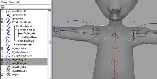
Creating the left and right FKarm_ctrl to aid in the prevention of Gimbal lock.
b. In the OUTLINER, click on the FK_left_shoulder_ctrl with the MMB and drag it onto the left_FKarm_ctrl.
c. In the OUTLINER, click on the FK_right_shoulder_ctrl with the MMB and drag it onto the right_FKarm_ctrl.
25. Now that we are finished with the FK arm, we can hide it to work on the IK arm. In the OUTLINER, select the left_FKarm_ctrl and the right_FKarm_ctrl – then press (ctrl+h) to hide them.
26. In the OUTLINER, select the IK_left_shoulder joint chain and the IK_right_shoulder joint chain – then press (shift + h) to display the chain.
27. Create the left IK arm by doing the following:
a. Set a preferred angle in the left arm by doing the following:
i. Select the IK_left_elbow joint and in the channel box set the following: RotateY: type “–25”.
ii. Select the IK_left_shoulder joint, then go to [Skeleton > Set Preferred Angle].
iii. Select the IK_left_elbow joint and in the channel box set the following: RotateY: type “0”. (MAKE SURE YOU DO THIS to make the elbow straight again.)

Setting a preferred angle on the left arm.
![]()
We must first set a preferred angle in the arm so that Maya knows which direction to bend the arm when we run the IK solver through the joints. Be sure to straighten the arm again afterward.
b. Go to [Skeleton > IK Handle Tool – option box] and set the following:
i. Click “reset tool” then under IK Handle Settings change the following:
Place a check mark in the box next to Sticky.
Then click “close”.
c. In the PERSPECTIVE window, click on the IK_ left_shoulder joint (to define the start of the IK joint chain) then on the IK_ left_wrist joint. (To define the end of the chain. An IK handle appears at the end of the chain.)
d. In the OUTLINER, double-click on ikHandle1 and rename it leftArm_ikHandle. (This chain will control the arm movement.)
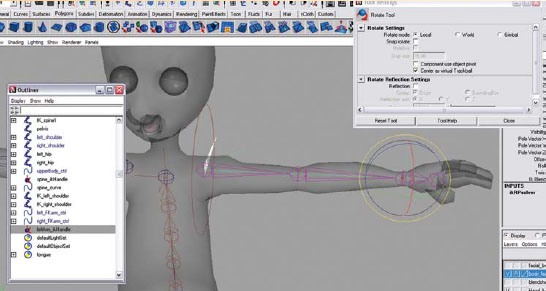
Creating an RP IK solver in the left arm.
e. It is a great idea to check to make sure the IK handle moves correctly along the X axis. You can do this by doing the following:
f. Select the leftArm_ikHandle and move the IK handle along the X axis (red arrow) toward the body to confirm that the arm bends in the correct direction. Be sure to press the (z) key to undo the move.
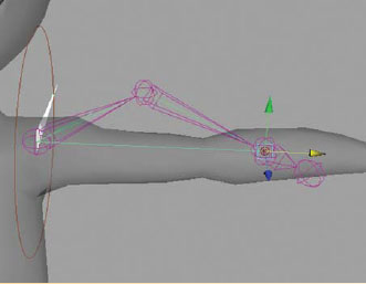
Moving the leftArm_ikHandle along the X axis to make sure the arm bends correctly.
g. Go to [Skeleton > IK Handle Tool – option box] and set the following:
i. Under IK Handle Settings change the following:
Current solver: choose “ikSCsolver”.
Keep a check mark in the box next to Sticky.
Then click “close”.
h. In the PERSPECTIVE window, click on the IK_ left_wrist joint (to define the start of the IK joint chain) then on the IK_ left_palm joint. (To define the end of the chain. An IK handle appears at the end of the chain.)
i. In the OUTLINER, double-click on ikHandle1 and rename it leftWrist_ikHandle. (This chain will control the wrist movement.)

Creating a Single Chain IK solver in the left wrist.
![]()
Unfortunately, IK solvers do not mirror the way we would like them to behave, so we will need to repeat the steps for the right side. You can repeat the right arm when suggested to do so, or wait until the end to redo the right side all at once.
28. Repeat the above to create the right IK arm.
29. Now that we are finished with the IK arm, we make everything visible again. In the OUTLINER, select the left_FKarm_ctrl, hold down the (ctrl) key and select the right_FKarm_ctrl, the left_shoulder joint chain, the right_shoulder joint chain, and the UpperBody_ctrl – then press (shift + h) to display them.

Displaying the hidden arms in the OUTLINER.
30. Create a control system for the IK arm by doing the following:
a. First create the controllers by doing the following:
i. Go to [Create > NURBS Primitives > Circle].
ii. In the channel box, rename the circle left_IKhand_ctrl.
iii. In PERSPECTIVE view, select the move tool by pressing (w), hold down the (v) key, position your cursor over the IK_left_wrist joint, and click the MMB and drag it slightly to snap the left_IKhand_ctrl into place.
iv. Use the scale tool by pressing (r) and resize the circle if necessary. (This control should be scaled large enough that it is OUTSIDE of the character’s arm to make it easy to select.)
v. With the left_IKhand_ctrl selected, go to [Modify > Freeze Transformations]. (To return both translate and rotate values to 0 and the scale values to 1.)
vi. Select the left_IKhand_ctrl and reposition the curve around the hand by doing the following:
1. Press the (F8) key.
2. Choose the “select point components” button in the Status Line.
3. Using the move tool by pressing (w), click and drag around the points of the circle and position them over the right wrist.
vii. Change the rotation order for the left_IKhand_ctrl by doing the following:
1. With the left_IKhand_ctrl selected, open the attribute editor by pressing (ctrl+a).
2. Under Transform Attributes set the following:
a. Rotate order: choose “ZYX”.

Creating and positioning the left_IKhand_ctrl to control the leftArm_ikHandle.
viii. Duplicate the left_IKhand_ctrl by going to [Edit > Duplicate] or press (ctrl+d).
ix. In the OUTLINER, double-click on left_IKhand_ctrl1 and rename it right_IKhand_ctrl.
x. In PERSPECTIVE view, select the move tool by pressing (w), hold down the (v) key, position your cursor over the IK_right_wrist joint, click the MMB and drag it slightly to snap the right_IKhand_ctrl into place.
ix. With the right_IKhand_ctrl selected set the following in the channel box: RotateZ: type “180” (this will flip the controller over the right hand).
xii. With the right_IKhand_ctrl selected, go to [Modify > Freeze Transformations]. (To return both translate and rotate values to 0 and the scale values to 1.)
xiii. In the channel box, rename the circle left_IKelbow_ctrl.
xiv. In PERSPECTIVE view, with the left_IKelbow_ctrl selected, select the move tool by pressing (w), hold down the (v) key, position your cursor over the IK_left_elbow joint, click the MMB and drag it slightly to snap the left_IKelbow_ctrl into place.
xvi. With the move tool, click on the Z axis (blue arrow) and move the controller arm distance behind the character.
xvii. With the left_IKelbow_ctrl selected set the following in the channel box: RotateX: type “90”.
xviii. Use the scale tool by pressing (r) and resize the circle if necessary.
xix. With the left_IKelbow_ctrl selected, go to [Modify > Freeze Transformations]. (To return both translate and rotate values to 0 and the scale values to 1.)
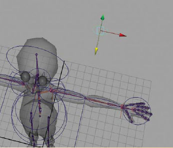
Creating and positioning the left_IKelbow_ctrl to control the leftArm_ikHandle’s pole vector.
xx. he rotation order does not need to be changed on this controller because rotations are not necessary for control.
xxi. Duplicate the left_IKelbow_ctrl by going to [Edit > Duplicate] or press (ctrl+d).
xxii. In the OUTLINER, double-click on left_IKelbow_ctrl1 and rename it right_IKelbow_ctrl.
xxiii. In PERSPECTIVE view, select the move tool by pressing (w) and click on the X axis (red arrow), hold down the (v) key, position your cursor over the IK_right_elbow joint, click the LMB (left mouse button) and drag it slightly to snap the right_IKelbow_ctrl into place. (By selecting the X axis first, the move is constrained to that axis only.)
xxiv. With the right_IKelbow_ctrl selected, go to [Modify > Freeze Transformations]. (To return both translate and rotate values to 0 and the scale values to 1.)
31. Create control between the controllers and the IK handles by doing the following:
a. In the OUTLINER, click on the left_IKhand_ctrl (the leader), hold down the (ctrl) key and click on the leftArm_ikHandle (the follower), then go to [Constrain > Point – option box] and set the following:
1. Go to [Edit > Reset Settings].
2. Place a check mark in the box next to Maintain Offset.
Then click “add”.

Creating a point constraint between the left_IKhand_ctrl (leader) and the leftArm_ikHandle (follower).
![]()
This point constraint constrains the arm IK handle’s translations to the controller so that when you move the controller, the IK handle follows it, BUT, when you rotate the controller, the IK handle does not. This is important in the arm setup because we don’t want the entire arm to rotate when we rotate the hand.
b. In the OUTLINER, click on the leftWrist_ikHandle with the MMB and drag it onto the left_IKhand_ctrl. (This makes the leftWrist_ikHandle child to the left_IKhand_ctrl so that it moves and rotates with the left_IKhand_ctrl, which is desirable in this case so that the wrist rotates with the forearm.)
c. In the OUTLINER, click on the left_IKelbow_ctrl (the leader), hold down the (ctrl) key and click on the leftArm_ikHandle (the follower), then go to [Constrain > Pole Vector].

Creating a pole vector constraint between the left_IKelbow_ctrl (leader) and the leftArm_ikHandle (follower).
d. Repeat the constraints and parenting for the right arm.
e. Integrate the elbow controls into the existing spine controls by doing the following:
i. In the PERSPECTIVE window, select the left_IKelbow_ctrl, shift select the right_IKelbow_ctrl, the spine_shoulder_ctrl, and press (p) on the keyboard to parent.
![]()
You can now test out your arm controls. Select the left_IKhand_ctrl and move it around toward the body so that the elbow bends. You can also rotate this control to control the wrist. Select the left_IKelbow_ctrl and move it up and down to control the position of the elbow. Be sure to press the (z) key several times to undo the moves.
32. The next part will create an integrated arm where the joint chain that will eventually control the geometry has a switch to choose between the FK control arm and the IK control arm. Do the following:
a. Create a constraint system with two leaders, the FK control arm and the IK control arm. To set this up, do the following:
i. In the OUTLINER, select the left_shoulder, and while holding down the (ctrl) key, select the left_FKarm_ctrl and the IK_left_shoulder.
ii. Press (ctrl+g) to create a group of the three arms to make it easier to select.
iii. In the OUTLINER, double-click on group1 and rename it leftArm_grp.
iv. In the OUTLINER, select the right_shoulder, and while holding down the (ctrl) key, select the right_FKarm_ctrl and the IK_right_shoulder.
v. Press (ctrl+g) to create a group of the three arms to make it easier to select.
;vi. In the OUTLINER, double-click on group1 and rename it rightArm_grp.
vii. In the OUTLINER, hold down the shift key and click on the plus sign ( + ) next to the leftArm_grp to open the hierarchy and display the children. (You might want to collapse the palm, pinkyPalm, and thumbPalm joints so that the arm hierarchy is not as long – you can do this by clicking on the negative sign ([–]) next to them.)
viii. In the OUTLINER, click first on the FK_left_shoulder_ctrl, and while holding down the (ctrl) key, click second on the IK_left_shoulder and click third on the left_shoulder, then go to [Constrain > Orient – option box] and set the following:
1. Go to [Edit > Reset Settings].
2. Place a check mark in the box next to Maintain Offset.
Then click “add”.

Creating an orient constraint between the FK_left_shoulder_ctrl, the IK_left shoulder (both leaders) and the left_shoulder (follower).
ix. In the OUTLINER, click first on the FK_left_elbow_ctrl, and while holding down the (ctrl) key, click second on the IK_left_elbow and click third on the left_elbow, then press the (g) key to repeat the last command of applying an orient constraint.

Creating an orient constraint between the FK_left_elbow_ctrl, the IK_left elbow (both leaders) and the left_elbow (follower).
x. In the OUTLINER, click first on the FK_left_hand_ctrl, and while holding down the (ctrl) key, click second on the IK_left_wrist and click third on the left_wrist, then press the (g) key to repeat the last command of applying an orient constraint.

Creating an orient constraint between the FK_left_hand_ctrl, the IK_left wrist (both leaders) and the left_wrist (follower).
ix. In the OUTLINER, click first on the FK_left_hand_ctrl, and while holding down the (ctrl) key, click second on the IK_left_wrist and click third on the left_forearm, then go to [Constrain > Orient – option box] and set the following:
1. Go to [Edit > Reset Settings].
2. Place a check mark in the box next to Maintain Offset.
3. Under Constraint axes: place a check mark in the box next to X.
Then click “add”.
(This constrain for the forearm is different from the other joints because we only want the forearm to twist with the wrist. It would look like the character’s arm is broken if the forearm bent with the wrist. Because of this we only constrain the X axis.)

Creating an orient constraint between the FK_left_hand_ctrl, the IK_left wrist (both leaders) and the left_forearm (follower).
33. Repeat the constraints on the right arm.
![]()
When creating the orient constraints on the right arm, MAKE SURE TO RESET THE ORIENT CONSTRAINT TO CONSTRAIN ALL AXES. To do this, open the option box and click the “reset tool” button as noted in the directions.
34. Create a switch to change the leader between the FK control arm and the IK control arm. To set this up, do the following:
a. Go to [Create > NURBS Primitives > Circle].
b. In the channel box, rename nurbsCircle1 to left_FKIK_switch.
c. In PERSPECTIVE view, with the left_FKIK_switch selected, select the move tool by pressing (w), hold down the (v) key, position your cursor over the left_wrist joint, and click the MMB and drag it slightly to snap the left_FKIK_switch into place.
i. With the move tool, click on the Y axis (green arrow) and move the controller slightly above the wrist.
ii. With the left_FKIK_switch selected, select the scale tool by pressing (r) and scale the left_FKIK_switch smaller.
iii. With the left_FKIK_switch selected set the following in the channel box: RotateX: type “90”.
iv. The rotation order does not need to be changed on this controller, because rotations are not necessary for control.

Creating and positioning the left_FKIK_switch to control the ability to turn the orient constraints on and off between the control arms.
v. Duplicate the left_FKIK_switch by going to [Edit > Duplicate] or press (ctrl+d).
vi. In the OUTLINER, double-click on left_FKIK_switch1 and rename it right_FKIK_switch.
vii. In PERSPECTIVE view, select the move tool by pressing (w) and click on the X axis (red arrow), hold down the (v) key, position your cursor over the IK_right_wrist joint, and click the LMB and drag it slightly to snap the left_FKIK_switch1 into place. (By selecting the X axis first, the move is constrained to that axis only.)
d. In the OUTLINER, hold down the shift key and click on the plus sign (+) next to the FK_left_shoulder_ctrl to open the hierarchy and display the children.
e. In the OUTLINER, hold down the MMB, click on the left_FKIK_switch and drag it onto the left_wrist joint. (This makes the left_FKIK_switch child to the left_wrist joint.)
f. In the OUTLINER, hold down the shift key and click on the plus sign (+) next to the FK_right_shoulder_ctrl to open the hierarchy and display the children.
g. In the OUTLINER, hold down the MMB, click on the right_FKIK_switch and drag it onto the right_wrist joint. (This makes the right_FKIK_switch child to the right_wrist joint.)
h. With the right_FKIK_switch selected, hold down the (shift) key and select left_FKIK_switch, then go to [Modify > Freeze Transformations]. (To return both translate and rotate values to 0 and the scale values to 1.)
i. With the left_FKIK_switch and right_FKIK_switch selected, go to [Modify > Add Attribute]. Using the default settings, enter the following:
i. Attribute name: type “FKIK”.
ii. Under Numeric Attribute Properties.
1. Minimum: type “0”.
2. Maximum: type “10”.
iii. Click “OK”.
![]() Data Type to Float. (Floating point numbers (or floats) have a fractional part (decimal points), allowing us to set any value between a minimum value and a maximum value which allows a smooth transition from one number to the next. The only type of attributes that we will be using in this setup is a Float.)
Data Type to Float. (Floating point numbers (or floats) have a fractional part (decimal points), allowing us to set any value between a minimum value and a maximum value which allows a smooth transition from one number to the next. The only type of attributes that we will be using in this setup is a Float.)

Adding a custom attribute to the FKIK_switch controllers using [Modify > Add Attribute].
35. Make the switch function. To set this up, we will use Set Driven Key to turn the constraints on and off. To sum things up, when the FKIK switch is set to 0, the FK constraints will be turned on and the IK constraints will be turned off so that the arm will follow the FK control arm. When the FKIK switch is set to 10, the IK constraints will be turned on and the FK constraints will be turned off so that the arm will follow the IK control arm. Do the following:
a. In the OUTLINER, select the left_shoulder_orientConstraint1 and go to [Animate > Set Driven Key > Set…]. (This places left_shoulder_orientConstraint1 as the driven in the Set Driven Key window.)
i. Select the left_FKIK_switch and click “Load Driver” in the Set Driven Key window.
ii. In the Driver section of the Set Driven Key window, choose “FKIK” in the right column.
iii. In the Driven section of the Set Driven Key window, choose “FK_left_shoulder_ctrlW0” in the right column, hold down the (shift) key and also click on “IK_left_shoulderW1”.
iv. In the Driven section of the Set Driven Key window, click on left_shoulder_orientConstraint1to select it.
v. In the channel box, change IK_left_shoulderW1 to “0”.
vi. In the Set Driven Key window, click “Key”. (This click changes the Driven attributes to orange in the channel box, indicating a key has been set on the shoulder constraint.)

Loading the Set Driven Key window and setting the first key so that when the FKIK_switch is set to “0”, the shoulder will follow the FK_controlled shoulder.
vii. In the Driver section of the Set Driven Key window, click on left_FKIK_switch to select it.
viii. In the channel box, change FKIK to “10”.
ix. In the Driven section of the Set Driven Key window, click on left_shoulder_orientConstraint1to select it.
x. In the channel box, change FK_left_spine_shoulder_ctrlW0 to “0” and IK_left_shoulderW1 to “1”.
ix. In the Set Driven Key window, click “Key”.
b. Repeat these steps for the elbow, forearm, and wrist.

Setting the second key so that when the FKIK_switch is set to “10”, the shoulder will follow the IK_controlled shoulder.
36. Make the switch also to control the visibility of the controllers. Since the IK controllers will only work when the FKIK switch is set to 10, we can hide them when IK has been turned off. Since the FK controllers will only work when the FKIK switch is set to 0, we can hide them when IK has been turned on. Do the following:
a. We will start with the FK controls:
i. In the OUTLINER, select the left_FKarm_ctrl, and then click “Load Driven” in the Set Driven Key window. (We only need the left_FKarm_ctrl since it is the parent of the other FK controls)
ii. The left_FKIK_switch remains the Driver with “FKIK” chosen in the right column.
iii. In the Driven section of the Set Driven Key window, choose “visibility” in the right column.
iv. In the Driven section of the Set Driven Key window, click on left_FKarm_ctrl to select it.
v. In the Channel Box, change visibility to “0” which turns the visibility off (since the last step ended with the FKIK switch on 10, we will key the FK visibility off first to save some steps.)
vi. In the Set Driven Key window, click “Key”
i. In the Driver section of the Set Driven Key window, click on left_FKIK_switch to select it.
ii. In the channel box, change FKIK to “0”.
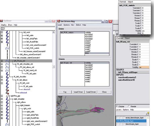
Loading the Set Driven Key window and setting the first key so that when the FKIK_switch is set to “10”, the FK controllers are not visible.
iii. In the Driven section of the Set Driven Key window, click on left_FKarm_ctrl to select it.
iv. In the channel box, change visibility to “1” which turns the visibility on.
v. In the Set Driven Key window, click “Key”.
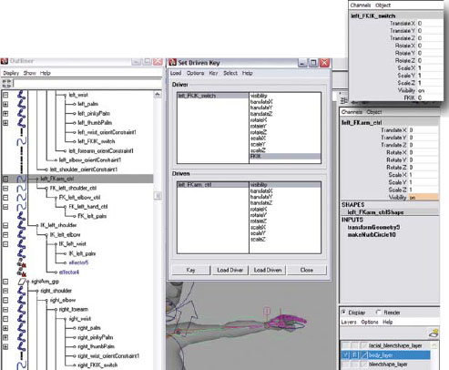
Setting the second key so that when the FKIK_switch is set to “0”, the FK controllers are visible.
c. Repeat this process for the IK controls:
i. In the PERSPECTIVE window, select the left_IKhand_ctrl, hold down the (ctrl) key and click left_IKelbow_ctrl, then click “Load Driven” in the Set Driven Key window.
ii. The left_FKIK_switch remains the Driver with “FKIK” chosen in the right column.
iii. In the Driven section of the Set Driven Key window, choose “visibility” in the right column.
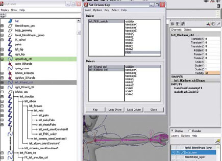
Loading the Set Driven Key window and setting the first key so that when the FKIK_switch is set to “0”, the IK controllers are not visible.
iv. In the Driven section of the Set Driven Key window, click on left_IKarm_ctrl, hold down the (shift) key and also click on left_IKelbow_ctrl to select them.

Setting the second key so that when the FKIK_switch is set to “10”, the IK controllers are visible.
v. In the channel box, change visibility to “0”.
vi. In the Set Driven Key window, click “Key”.
vii. In the Driver section of the Set Driven Key window, click on left_FKIK_switch to select it.
viii. In the channel box, change FKIK to “10”.
ix. In the Driven section of the Set Driven Key window, click on left_IKarm_ctrl, hold down the (shift) key and also click on left_IKelbow_ctrl to select them.
x. In the channel box, change visibility to “1”.
ix. In the Set Driven Key window, click “Key”.
xii. Repeat making the switch function for the right arm.
37. Integrate the FK and IK arms into the existing shoulder controls by doing the following:
a. In the PERSPECTIVE window, click on the left_FKIK_switch, hold down the (shift) key and click the right_FKIK_switch. In the channel box, set the FKIK attribute to “0” to turn IK off.
b. In the OUTLINER, click on the leftArm_grp, hold down the (shift) key on the keyboard and in the PERSPECTIVE window, click on the left_clavicle_ctrl and press (p) on the keyboard to parent them.
c. In the OUTLINER, click on the rightArm_grp, hold down the (shift) key on the keyboard and in the PERSPECTIVE window, click on the right_clavicle_ctrl and press (p) on the keyboard to parent them.
38. Save your scene file. Name your scene 06_asgn04.ma.
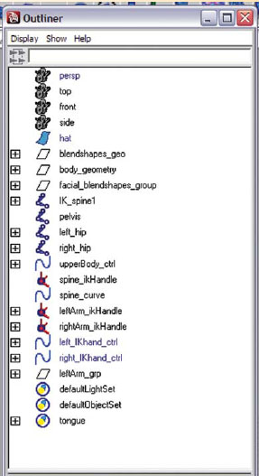
The new OUTLINER hierarchy after integrating the arms into the existing spine controls.
Assignment 6.5: Creating a Control System for the Fingers
1. Open Maya and set your project.
a. From your computer’s desktop, go to [Start > Programs] and select Maya.
b. Once Maya is open go to [File > Project > Set…] and browse to your project folder then click “OK”.
2. Open your last saved file: Go to [File > Open] and select 06_asgn04.ma.
3. Continue working in X-ray mode.
4. Make sure that your geometry layer is set to R for reference so that you are unable to select the geometry by mistake when working.
5. To make selection easier open your OUTLINER by going to [Windows > Outliner].
6. Create a control system for the fingers by doing the following:
a. Go to [Create > NURBS Primitives > Circle].
b. In the channel box, rename nurbsCircle1 to left_finger_ctrl.
c. In PERSPECTIVE view, with the left_finger_ctrl selected, select the move tool by pressing (w), hold down the (v) key, position your cursor over the left_wrist joint, and click the MMB and drag it slightly to snap the left_finger_ctrl into place.
i. With the left_finger_ctrl selected, set the following in the channel box: RotateZ: type “90”.
ii. With the move tool, click on the Y axis (green arrow) and move the controller slightly above the wrist, around the left_FKIK_switch.
iii. With the left_finger_ctrl selected, select the scale tool by pressing (r) and scale the left_finger_ctrl larger than the left_FKIK_switch.
iv. The rotation order does not need to be changed on this controller, because rotations are not necessary for control.

Creating and positioning the left_finger_ctrl.
v. Duplicate the left_finger_ctrl by going to [Edit > Duplicate] or press (ctrl+d).
vi. In the OUTLINER, double-click on left_finger_ctrl1 and rename it right_finger_ctrl.
vii. In PERSPECTIVE view, select the move tool by pressing (w) and click on the X axis (red arrow), hold down the (v) key, position your cursor over the right_finger_ctrl, and click the MMB and drag it slightly to snap the right_finger_ctrl into place. (By selecting the X axis first, the move is constrained to that axis only.)
d. In the PERSPECTIVE window, select the left_finger_ctrl, hold down the (shift) key and click the left_FKIK_switch, and press (p) to parent.
e. In the PERSPECTIVE window, select the right_finger_ctrl, hold down the (shift) key and click the right_FKIK_switch, and press (p) to parent.
f. With the right_finger_ctrl selected, hold down the (shift) key and select left_finger_ctrl, then go to [Modify > Freeze Transformations]. (To return both translate and rotate values to 0 and the scale values to 1.)
7. Add attributes to the finger control for the finger movements by doing the following:
a. With the left_finger_ctrl and right_finger_ctrl selected, go to [Modify > Add Attributes] and using the default settings, enter the following:
i. Attribute name: type “indexFlexCurl”.
ii. Under Numeric Attribute Properties
1. Minimum: type “–10”.
2. Maximum: type “10”.
3. Click “Add”.

Adding custom attributes to the fingers using [Modify > Add Attribute].
i. Attribute name: type “middleFlexCurl”.
ii. Under Numeric Attribute Properties
1. Minimum: type “–10”.
2. Maximum: type “10”.
3. Click “Add”
c. Enter the following:
i. Attribute name: type “ringFlexCurl”.
ii. Under Numeric Attribute Properties
1. Minimum: type “–10”.
2. Maximum: type “10”.
3. Click “Add”.
d. Enter the following:
i. Attribute name: type “pinkyFlexCurl”.
ii. Under Numeric Attribute Properties
1. Minimum: type “–10”.
2. Maximum: type “10”.
3. Click “Add”.
e. Enter the following:
i. Attribute name: type “thumbFlexCurl”.
ii. Under Numeric Attribute Properties
1. Minimum: type “–10”.
2. Maximum: type “10”.
3. Click “Add”.
f. Enter the following:
i. Attribute name: type “thumbSpread”.
ii. Under Numeric Attribute Properties
1. Minimum: type “–10”.
2. Maximum: type “10”.
3. Click “Add”.
g. Enter the following:
i. Attribute name: type “fingerSpread”.
ii. Under Numeric Attribute Properties
1. Minimum: type “–10”.
2. Maximum: type “10”.
3. Click “OK”.
i. Attribute name: type “grab”.
ii. Under Numeric Attribute Properties
1. Minimum: type “0”.
2. Maximum: type “10”.
3. Click “Add”.
These are the attributes that you will control with Set Driven Key. They now show up in the channel box for the left_finger_ctrl. For more control over the fingers, you might even want break apart the finger motion into two separate attributes for each finger: a bend attribute for the first knuckle of the finger and a curl attribute for the last two knuckles. If you make a mistake, you can go to [Modify > Edit Attribute] to make changes.

The left_finger_ctrl in the channel box, with all of the finger attributes added.
![]()
When creating the poses for the fingers using Set Driven Key, you can do all the selecting and manipulating in the work area (PERSPECTIVE window) or use the OUTLINER or Hypergraph if selecting the joints in the view panel becomes too tedious. The joints can be selected from inside the Set Driven Key editor as well but make sure to reselect them all in the “Driven” section before pressing the “Key” button in the set driven window.
8. Use Set Driven Key to add functionality to the attributes by doing the following:
a. In the OUTLINER, select the left_index1 joint, hold down the (ctrl) key and click left_index2 joint and left_index3 joint and go to [Animate > Set Driven Key > Set…]. (This places the joints as the driven in the Set Driven Key window.)
b. Add functionality to the indexFlexCurl attribute.
i. Select the left_finger_ctrl and click “Load Driver” in the Set Driven Key window.
ii. In the Driver section of the Set Driven Key window, choose “indexFlexCurl” in the right column.
iii. In the Driven section of the Set Driven Key window, click on left_index1 joint, hold down the (ctrl) key and click left_index2 joint and left_index3 to select them.
iv. In the Driven section of the Set Driven Key window, choose “rotate Z” in the right column.
v. In the Set Driven Key window, click “Key”. (This sets a default finger pose position at attribute value of 0.)

Loading the Set Driven Key window and setting the first key so that when the indexFlexCurl attribute is set to “0”, the index finger is in the default (original) position.
vi. In the Driver section of the Set Driven Key window, click on left_finger_ctrl to select it.
vii. In the channel box, change indexFlexCurl to “10”.
viii. In the PERSPECTIVE window, select the rotate tool by pressing the (e) key, rotate the index finger joints (index1, index2, and index3) along the Z axis (the blue ring) into a curled bent position. (Notice how your finger bends when you make a fist and try to mimic the position.)
ix. In the Set Driven Key window, click “Key”. (This sets a keyed pose of the finger in a bent position at attribute value of “10”.)
x. In the Driver section of the Set Driven Key window, click on left_finger_ctrl to select it.
ix. In the channel box, change indexFlexCurl to “–10”.

Setting the second key so that when the indexFlexCurl is set to “10”, the index finger is in the curled position.
xii. In the PERSPECTIVE window, select the rotate tool by pressing the (e) key, rotate the index finger joints (index1, index2, and index3) along the Z axis (the blue ring) into a flexed position. (Notice how your finger flexes when you stretch your hand and try to mimic the position.)
xiii. In the Set Driven Key window, click “Key”. (This click changes the Driven attributes to orange in the channel box, indicating a key has been set.)
xiv. To test and see if the control works, click on the word indexFlexCurl in the channel box, then in the PERSPECTIVE window, MMB click and drag your mouse left to right. You should see your character’s index finger flex and curl.

Setting the third key so that when the indexFlexCurl is set to “10”, the index finger is in the flexed position.
xv. In the channel box, change indexFlexCurl to “0”.
![]()
This exact procedure is repeated for the middle finger, the ring finger, the pinky, and the thumb. The important thing to remember is to make sure you change the driver attribute and reload the new joints as your driven.
c. Repeat these steps for the middleFlexCurl, ringFlexCurl, pinkyFlexCurl, and thumbFlexCurl attributes.
![]()
This procedure is similar for the thumbSpread and fingerSpread attributes. The main differences are the direction of the rotations and that multiple joints need to be rotated to achieve the position. Each position will be slightly different depending on how the hand was modeled.
d. Repeat these steps for the thumbSpread attribute.
i. In the Driver section of the Set Driven Key window, choose “thumbSpread” in the right column.
ii. Select the select the left_thumbPalm joint, hold down the (ctrl) key and click left_thumb1 joint, then click “Load Driven” in the Set Driven Key window.
iii. In the Driven section of the Set Driven Key window, click on left_thumbPalm joint, hold down the (ctrl) key and click left_thumb1 joint to select them.
iv. In the Driven section of the Set Driven Key window, click “rotate Y, then hold down the (ctrl) key and click rotate Z” in the right column.
v. In the Set Driven Key window, click “Key”. (This sets a default finger pose position at attribute value of 0.)

Loading the Set Driven Key window and setting the first key so that when the thumbSpread attribute is set to “0”, the thumb is in the default (original) position.
vi. In the Driver section of the Set Driven Key window, click on left_finger_ctrl to select it.
vii. In the channel box, change thumbSpread to “10”.
viii. In the PERSPECTIVE window, select the rotate tool by pressing the (e) key, rotate the thumb finger joints (thumbPalm and thumb1) along the Y or Z axis into a position next to the index finger.
ix. In the Set Driven Key window, click “Key”. (This sets a keyed pose of the thumb in a cupped position at attribute value of “10”.)
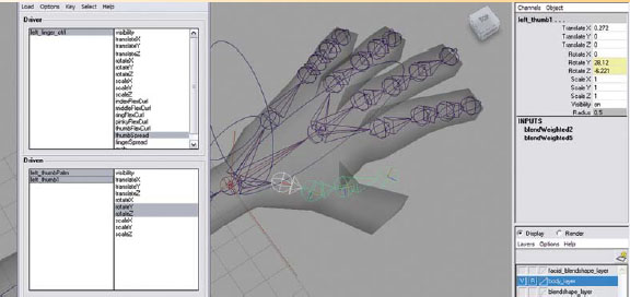
Setting the second key so that when the thumbSpread is set to “10”, the thumb is near the index finger in a closed position.
x. In the Driver section of the Set Driven Key window, click on left_finger_ctrl to select it.
xi. In the channel box, change thumbSpread to “–10”.
xii. In the PERSPECTIVE window, select the rotate tool by pressing the (e) key, rotate the thumb finger joints (thumbPalm and thumb1) along the Y or Z axis into a position away from the index finger.
xiii. In the Set Driven Key window, click “Key”. (This sets a keyed pose of the thumb in a cupped position at attribute value of “–10”.)
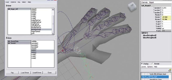
Setting the third key so that when the thumbSpread is set to “–10”, the thumb is away from the index finger in a spread position.
xiv. To test and see if the control works, click on the word thumbSpread in the channel box, then in the PERSPECTIVE window, MMB click and drag your mouse left to right.
xv. In the channel box, change thumbSpread to “0”.
e. Repeat these steps for the fingerSpread attribute.
i. In the Driver section of the Set Driven Key window, choose “fingerSpread” in the right column.
ii. Select the select the left_index1 joint, hold down the (ctrl) key and click the left_middle1 joint, the left_ring1 joint, and the left_pinky1 joint, click “Load Driven” in the Set Driven Key window.
iii. In the Driven section of the Set Driven Key window, click the left_index1 joint, hold down the (ctrl) key and click the left_middle1 joint, the left_ring1 joint, and the left_pinky1 joint to select them.
iv. In the Driven section of the Set Driven Key window, choose “rotate Y” in the right column.
v. In the Set Driven Key window, click “Key”.
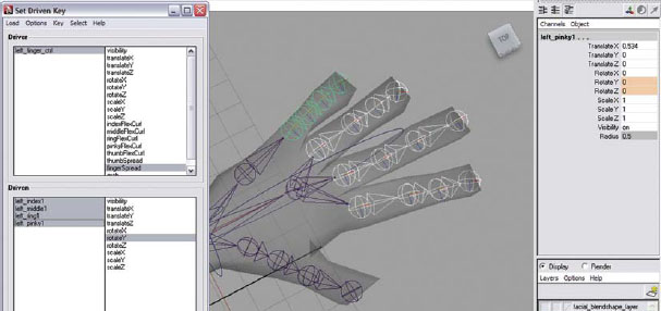
Loading the Set Driven Key window and setting the first key so that when the fingerSpread attribute is set to “0”, the hand is in the default (original) position.
vi. In the Driver section of the Set Driven Key window, click on left_finger_ctrl to select it.
vii. In the channel box, change fingerSpread to “10”.
viii. In the PERSPECTIVE window, select the rotate tool by pressing the (e) key, rotate the finger joints (left_index1, left_middle1, left_ring1, and left_pinky1) along the Y axis (the green ring) into a squeezed closed position where all of the fingers would be touching.
ix. In the Set Driven Key window, click “Key”.

Setting the second key so that when the fingerSpread is set to “10”, the fingers are in a closed position.
x. In the Driver section of the Set Driven Key window, click on left_finger_ctrl to select it.
ix. In the channel box, change fingerSpread to “–10”.
xii. In the PERSPECTIVE window, select the rotate tool by pressing the (e) key, rotate the finger joints (left_index1, left_middle1, left_ring1, and left_pinky1) along the Y axis (the green ring) into a spread open position.
xiii. In the Set Driven Key window, click “Key”.

Setting the third key so that when the fingerSpread is set to “–10”, the fingers are in a spread open position.
xiv. To test and see if the control works, click on the word fingerSpread in the channel box, then in the PERSPECTIVE window, MMB click and drag your mouse left to right. You should see your character’s fingers spread and close.
xv. In the channel box, change fingerSpread to “0”.
![]()
This last position is for grabbing. It’s a position where the thumb and pinky are cupped forward with the rest of the hand. Think about a pose where the hand is reaching for a doorknob.
f. Repeat these steps for the grab attribute.
i. In the Driver section of the Set Driven Key window, choose “grab” in the right column.
ii. Select all of the joints in the hand (except for the Tip joints) and click “Load Driven” in the Set Driven Key window.
iii. In the Driven section of the Set Driven Key window, click on all of the joints to select them.
iv. In the Driven section of the Set Driven Key window, click “rotate X, then hold down the (ctrl) key and click rotate Y and rotate Z” in the right column.
v. In the Set Driven Key window, click “Key”. (This sets a default finger pose position at attribute value of 0.)

Loading the Set Driven Key window and setting the first key so that when the grab attribute is set to “0”, the hand is in the default (original) position.
vi. In the Driver section of the Set Driven Key window, click on left_finger_ctrl to select it.
vii. In the channel box, change grab to “10”.
viii. In the PERSPECTIVE window, select the rotate tool by pressing the (e) key, and rotate the finger joints along the X, Y, or Z axis into a cupped bent position. (The goal is to make it so that the hand can grab something, so they would be rotated slightly inward toward the palm.)
ix. In the Set Driven Key window, click “Key”. (This sets a keyed pose of the fingers in a cupped position at attribute value of “10”.)

Setting the second key so that when the grab is set to “10”, the fingers are in a cupped position.
x. To test and see if the control works, click on the word pinkyCup in the channel box, then in the PERSPECTIVE window, MMB click and drag your mouse left to right.
ix. In the channel box, change pinkyCup to “0”.
9. Repeat adding functionality to the attributes for the right fingers.
10. Save your scene file. Name your scene 06_asgn05.ma.
Assignment 6.6: Creating a Control System for the Legs and Feet
For the leg control, we will only be setting up an IK control system since most of the time our characters will be walking on something. If you think you need an FK control system, you can follow the setup for the arms and adapt it to the legs.
1. Open Maya and set your project.
a. From your computer’s desktop, go to [Start > Programs] and select Maya.
b. Once Maya is open, go to [File > Project > Set…] and browse to your project folder then click “OK”.
2. Open your last saved file: Go to [File > Open] and select 06_asgn05.ma.
3. Continue working in X-ray mode.
4. Make sure that your geometry layer is set to R for reference so that you are unable to select the geometry by mistake when working.
5. To make selection easier open your OUTLINER by going to [Windows > Outliner].
6. Create the IK in the leg by doing the following:
a. Set a preferred angle in the left leg by doing the following:
i. Select the left_knee joint and the right_knee joint in the channel box set the following: RotateY: type “40”.
ii. Select the left_hip joint, then go to [Skeleton > Set Preferred Angle].
iii. Select the left_knee joint and in the channel box set the following: RotateY: type “0” (this will make the knee straight again).
(We must first set a preferred angle in the leg so that Maya knows which direction to bend the leg when we run the IK solver through the joints.)
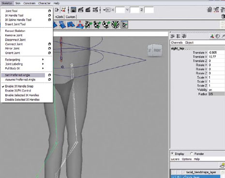
Setting a preferred angle on the legs.
b. Go to [Skeleton > IK Handle Tool – option box] and set the following:
i. Click “reset tool” then under IK Handle Settings change the following:
Place a check mark in the box next to Sticky.
Then click “close”.
c. In the PERSPECTIVE window, click on the left_hip joint (to define the start of the IK joint chain) then on the left_ankle joint (to define the end of the chain; an IK handle appears at the end of the chain.) See image on page 251
d. In the OUTLINER, double-click on ikHandle1 and rename it leftLeg_ikHandle. (This chain will control the leg movement.)
e. It is a great idea to check to make sure the IK handle moves correctly along the Y axis. You can do this by doing the following:
f. Select the leftLeg_ikHandle and move the IK handle along the Y axis (green arrow) toward the body to confirm that the leg bends in the correct direction. Be sure to press the (z) key to undo the move.

Creating an RP IK solver in the left leg.
![]()
The direction that the IK handle points is not relevant. Its direction does not have any effect on the solver.

Moving the leftLeg_ikHandle along the Y axis to make sure the leg bends correctly.
g. Go to [Skeleton > IK Handle Tool – option box] and set the following:
i. Under IK Handle Settings change the following:
Current solver: choose “ikSCsolver”.
Keep a check mark in the box next to Sticky.
Then click “close”.
h. In the PERSPECTIVE window, click on the left_ankle joint (to define the start of the IK joint chain) then on the left_ball joint (to define the end of the chain. An IK handle appears at the end of the chain).
i. In the OUTLINER, double-click on ikHandle1 and rename it leftAnkle_ikHandle. (This chain will control the ankle movement.)

Creating an SC IK solver in the left ankle.
j. Press the (y) key to select the last tool used – in this case, the IK Handle Tool.
k. In the PERSPECTIVE window, click on the left_ball joint (to define the start of the IK joint chain) then on the left_toe joint (to define the end of the chain; an IK handle appears at the end of the chain).
l. In the OUTLINER, double-click on ikHandle1 and rename it leftToe_ikHandle. (This chain will control the toe movement.)
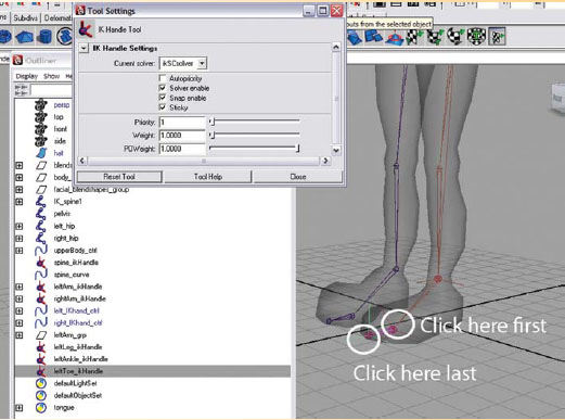
Creating an SC IK solver in the left toe.
m. Repeat steps to create the IK for the right leg.
7. Create a control system for the IK leg by doing the following:
a. First create the controllers by doing the following:
i. Go to [Create > NURBS Primitives > Circle].
ii. In the channel box, rename the circle left_foot_ctrl.
iii. In PERSPECTIVE view, select the move tool by pressing (w) on the keyboard and reposition the curve around the foot. DO NOT make it even with the sole of the foot as the animator will have a hard time seeing it through the floor plane. Make sure the pivot of the controller is in the ankle by doing the following: With the curve and the move tool still selected, press the (insert) key on the keyboard, hold down the (v) key, then position your cursor over the IK_left_ankle joint, click the MMB, and drag it slightly to snap the left_foot_ctrl pivot into place in the ankle.
iv. Use the scale tool by pressing (r) and resize the circle if necessary. (This control should be scaled large enough that it is OUTSIDE of the character’s foot to make it easy to select.)
v. With the left_foot_ctrl selected, go to [Modify > Freeze Transformations]. (To return both translate and rotate values to 0 and the scale values to 1.)
vi. Select the left_foot_ctrl and reshape the curve around the foot by doing the following:
1. Press the (F8) key.
2. Choose the “select point components” button in the Status Line.
3. Using the move tool by pressing (w), click and drag around the points of the circle and position them to reshape the curve into a shoeprint shape.
vii. Change the rotation order for the left_foot_ctrl by doing the following:
1. With the left_foot_ctrl selected, open the attribute editor by pressing (ctrl+a).
2. Select the left_foot_ctrl tab.
3. Under Transform Attributes set the following:
a. Rotate order: choose “ZXY”.
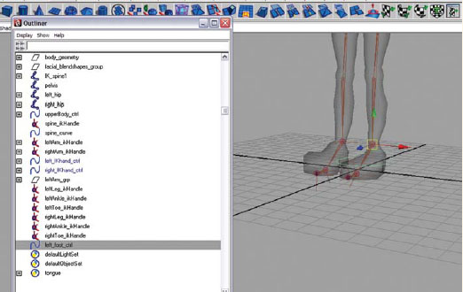
Creating and positioning the left_foot_ctrl.
viii. Duplicate the left_foot_ctrl by going to [Edit > Duplicate] or press (ctrl+d).
ix. In the OUTLINER, double-click on left_foot_ctrl1 and rename it right_foot_ctrl.
x. In PERSPECTIVE view, select the move tool by pressing (w), hold down the (v) key, position your cursor over the IK_right_ankle joint, and click the MMB and drag it slightly to snap the right_IKfoot_ctrl into place.
xi. With the right_foot_ctrl selected set the following in the channel box: ScaleX: type “−1” (this will flip the controller over the right foot).
xii. With the right_foot_ctrl selected, go to [Modify > Freeze Transformations]. (To return both translate and rotate values to 0 and the scale values to 1.)
xiv. In the channel box, rename the circle left_knee_ctrl.
xv. In PERSPECTIVE view, with the left_knee_ctrl selected, select the move tool by pressing (w), hold down the (v) key, position your cursor over the left knee joint, and click the MMB and drag it slightly to snap the left_knee_ctrl into place.
xvii. With the move tool, click on the Z axis (blue arrow) and move the controller leg distance in front of the character.
xviii. With the left_knee_ctrl selected set the following in the channel box: RotateX: type “90”.
xix. Use the scale tool by pressing (r) and resize the circle if necessary.
xix. With the left_knee_ctrl selected, go to [Modify > Freeze Transformations]. (To return both translate and rotate values to 0 and the scale values to 1.)
xx. The rotation order does not need to be changed on this controller, because rotations are not necessary for control.

Creating and positioning the left_knee_ctrl to control the leftLeg_ikHandle’s pole vector.
xxi. uplicate the left_knee_ctrl by going to [Edit > Duplicate] or press (ctrl+d).
xxii. In the OUTLINER, double-click on left_knee_ctrl1 and rename it right_knee_ctrl.
xxiii. In PERSPECTIVE view, select the move tool by pressing (w) and click on the X axis (red arrow), hold down the (v) key, position your cursor over the right_knee joint, and click the LMB and drag it slightly to snap the right_knee_ctrl into place. (By selecting the X axis first, the move is constrained to that axis only.)
xxiv. With the right_knee_ctrl selected, go to [Modify > Freeze Transformations]. (To return both translate and rotate values to 0 and the scale values to 1.)
8. You may notice that we have created three separate IK chains for the leg and foot. A biped is capable of moving their toes, their ankle, and their leg independently from each other. Because of this, a single IK chain from the hip to the toe would not work for the control needed. We are now going to create a hierarchal system that provides maximum control and protect the animator from losing their work if an IK handle stops solving. Create control between the controllers and the IK handles by doing the following:
a. Go to [Create > Locator].
i. In the channel box, rename the locator left_heel_pivot.
ii. In PERSPECTIVE view, select the move tool by pressing (w), hold down the (v) key, then position your cursor over the left_ball joint (the joint in the ball of the foot), click the MMB and drag it slightly to snap the left_heel_pivot into place. Click on the Z axis (blue arrow) and move the locator to the heel of your character’s foot or shoe geometry.
iii. With the left_heel_pivot selected, go to [Modify > Freeze Transformations]. (To return both translate and rotate values to 0 and the scale values to 1.)

Creating and positioning a locator in the heel of the foot.
b. Repeat this again. Go to [Create > Locator].
i. In the channel box, rename the locator left_toe_pivot.
ii. In PERSPECTIVE view, select the move tool by pressing (w), hold down the (v) key, then position your cursor over the left_toe, joint, click the MMB and drag it slightly to snap the left_toe_pivot into place.
iii. With the left_toe_pivot selected, go to [Modify > Freeze Transformations]. (To return both translate and rotate values to 0 and the scale values to 1.)
c. Repeat this again. Go to [Create > Locator].
i. In the channel box, rename the locator left_ball_pivot.

Creating and positioning a locator in the toe of the foot.
ii. In PERSPECTIVE view, select the move tool by pressing (w), hold down the (v) key, then position your cursor over the left_ball joint, click the MMB and drag it slightly to snap the left_ball_pivot into place.
iii. With the left_ball_pivot selected, go to [Modify > Freeze Transformations]. (To return both translate and rotate values to 0 and the scale values to 1.)

Creating and positioning a locator in the ball of the foot.
iv. Duplicate the left_ball_pivot locator by going to [Edit > Duplicate] or press (ctrl+d).
v. In the OUTLINER, double-click on left_ball_pivot1 and rename it left_toe_wiggle.
d. Repeat (or duplicate) for the right side.
e. In the OUTLINER, click on the leftToe_ikHandle with the MMB and drag it onto the left_toe_wiggle locator. (This makes the leftToe_ikHandle child to the left_toe_wiggle locator.)
f. In the OUTLINER, click on the leftLeg_ikHandle with the MMB and drag it onto the left_ball_pivot locator. (This makes the leftLeg_ikHandle child to the left_ball_pivot locator.)
g. In the OUTLINER, click on the left_ball_pivot locator, hold down the (ctrl) key on the keyboard and click on the left_toe_wiggle locator, click on the leftAnkle_ikHandle, click on the left_toe_pivot locator and then press (p) on the keyboard. (This makes the left_ball_pivot locator, the left_toe_wiggle locator, and the leftAnkle_ikHandle child to the left_toe_pivot locator.)
h. In the OUTLINER, click on the left_toe_pivot locator with the MMB and drag it onto the left_heel_pivot locator. (This makes the left_toe_pivot locator child to the left_heel_pivot locator.)
i. In the OUTLINER, click on the left_heel_pivot locator with the MMB and drag it onto the left_foot_ctrl. (This makes the left_heel_pivot locator child to the left_foot_ctrl.)

The OUTLINER hierarchy before and after parenting the IK handles with the locators to make the foot hierarchy.
j. In the PERSPECTIVE window, click on the left_knee_ctrl (the leader), hold down the (ctrl) key and click on the leftLeg_ikHandle (the follower), then go to [Constrain > Pole Vector].
k. In the OUTLINER, click on the left_IKknee_ctrl with the MMB and drag it onto the left_foot_ctrl. (This makes the left_IKknee_ctrl child to the left_ foot_ctrl.)
l. Repeat for the right leg.

Creating a pole vector constraint between the left_knee_ctrl (leader) and the leftLeg_ikHandle (follower).
![]()
You can now test out some of your leg controls. Select the left_foot_ctrl and move it around toward the body so that the knee bends. You can also rotate this control to control the ankle. Select the left_knee_ctrl and move it left to right to control the position of the knee. Be sure to press the (z) key several times to undo the moves.
9. Add attributes to the foot control for the foot movements by doing the following:
a. Select the right_foot_ctrl, hold down the (shift) key and select left_foot_ctrl, then go to [Modify > Add Attribute] and enter the following:
i. Attribute name: type “footRoll”.
ii. Under Numeric Attribute Properties
1. Minimum: type “−5”.
2. Maximum: type “10”.
3. Click “Add”.
iii. Attribute name: type “heelTwist”
1. Click “Add”.
iv. Attribute name: type “toeTwist”
1. Click “Add”.
v. Attribute name: type “toeWiggle”
1. Click “OK”.

Adding custom attributes to the left_foot_ctrl and right_foot_ctrl using [Modify > Add Attribute].
10. Make the footRoll attribute function using Set Driven Key by doing the following:
a. In the OUTLINER, select the left_heel_pivot locator, hold down the (ctrl) key and click the left_toe_pivot locator and the left_ball_pivot locator, then go to [Animate > Set Driven Key > Set…].
![]()
When you are using Set Driven Key, remember to change the driver first, then the driven, then set a key (you are changing the pose for each keyframe, much like you do in the timeline when animating, but this is an attribute value instead of a time position).
b. Select the left_foot_ctrl and click “Load Driver” in the Set Driven Key window.
i. In the Driver section of the Set Driven Key window, choose “footRoll” in the right column.
ii. In the Driven section of the Set Driven Key window, click on the left_heel_pivot, hold down the (ctrl) key and click the left_toe_pivot and left_ball_pivot to select them.
iii. In the Driven section of the Set Driven Key window, choose “RotateX” in the right column.
iv. In the Set Driven Key window, click “Key”. (This sets a default position of the foot at the footRoll value of “0”.)
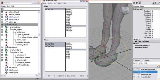
Loading the Set Driven Key window and setting the first key so that when the footRoll attribute is set to “0”, the foot is in the default (original) position.
v. In the Driver section of the Set Driven Key window, click on left_foot_ctrl to select it.
vi. In the channel box, change left_foot_ctrl to “−5”.
vii. In the Driven section of the Set Driven Key window, click on left_heel_pivot to select it.
viii. In the channel box, change RotateX to “−25”.
ix. In the Set Driven Key window, click “Key”. (This sets the key for the first pose of the foot roll – the heel contacting the ground with the toe raised.)

Setting the second key so that when the footRoll is set to “–5”, the heel is planted on the ground and the toe is in the air.
x. In the Driver section of the Set Driven Key window, click on left_foot_ctrl to select it.
ix. In the channel box, change left_foot_ctrl to “5”.
xii. In the Driven section of the Set Driven Key window, click on left_ball_pivot to select it.
xiii. In the channel box, change RotateX to “40”.
xiv. In the Set Driven Key window, click “Key”. (The second pose is already keyed at the default position, so this is the third pose of the foot roll – the heel leaving the ground with the ball on the ground.)
xv. In the Driven section of the Set Driven Key window, click on left_toe_pivot to select it.
xvi. In the Set Driven Key window, click “Key”.

Setting the third key so that when the footRoll is set to “5”, the ball is planted on the ground and the heel is in the air.
xvii. In the Driver section of the Set Driven Key window, click on left_foot_ctrl to select it.
xviii. In the channel box, change left_foot_ctrl to “10”.
xix. In the Driven section of the Set Driven Key window, click on left_toe_pivot to select it.
xx. In the channel box, change RotateX to “20”.
xxi. In the Set Driven Key window, click “Key”.
xxii. In the Driven section of the Set Driven Key window, click on left_ball_pivot to select it.
xxiii. In the channel box, change RotateX to “20”.
xxiv. In the Set Driven Key window, click “Key”. (This sets the key for the fourth pose of the foot roll – the ball leaving the ground with the tip of the toe on the ground.)
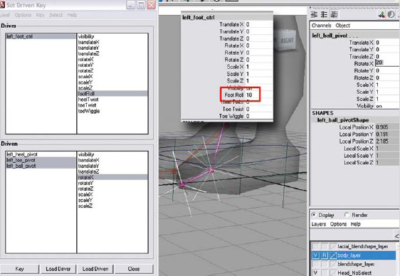
Setting the fourth key so that when the footRoll is set to “10”, the ball lifts off of the ground with the heel in the air.
c. Test the foot roll to make sure that it works properly.
i. In the Driver section of the Set Driven Key window, click on left_foot_ctrl to select it.
ii. In the channel box, click on the words Foot Roll.
iii. Place your cursor in the PERSPECTIVE window, click and hold your MMB, and drag left to right to see the foot roll.
d. Repeat for the right leg.
![]()
Remember, if you make a mistake you can start all over again by breaking the connections in the channel box. In the OUTLINER, select the left_heel_pivot locator, hold down the (ctrl) key and click the left_toe_pivot locator and the left_ball_pivot locator, then click on the word RotateX in the channel box, RMB and choose “break connections” which will delete the keyframes and you can start again.
11. Make the remaining attributes function using the Connection Editor. Do the following:
a. Go to [Window > General Editors > Connection Editor].
b. In the OUTLINER, select the left_foot_ctrl and click “Reload Left” Scroll down to the bottom of the list and choose “heelTwist”.
c. In the OUTLINER, select the left_heel_pivot and click “Reload Right” Scroll down to Rotate and click on the (+) to open the values. Choose “RotateY” to make the connection.

Using the connection editor to create a direct relationship between the left_foot_ctrl.heelTwist attribute and the left_heel_Pivot.rotateY attribute.
d. Click “Clear All”.
e. In the OUTLINER, select the left_foot_ctrl and click “Reload Left” Scroll down to the bottom of the list and choose “toeTwist”.
f. In the OUTLINER, select the left_toe_pivot and click “Reload Right” Scroll down to Rotate and click on the (+) to open the values. Choose “RotateY” to make the connection.

Using the connection editor to create a direct relationship between the left_foot_ctrl.toePivot attribute and the left_toe_Pivot.rotateY attribute.
h. In the OUTLINER, select the left_foot_ctrl and click “Reload Left” Scroll down to the bottom of the list and choose “toeWiggle”.
i. In the OUTLINER, select the left_toe_wiggle and click “Reload Right” Scroll down to Rotate and click on the (+) to open the values. Choose “RotateX” to make the connection.

Using the connection editor to create a direct relationship between the left_foot_ctrl.toeWiggle attribute and the left_toe_wiggle.rotateX attribute.
j. Test the attributes to make sure that they work properly.
i. In the OUTLINER section click on left_foot_ctrl to select it.
ii. In the channel box, click on the words heelTwist.
iii Place your cursor in the PERSPECTIVE window, click and hold your MMB, and drag left to right to see the foot roll, repeat the test for toeTwist and toeWiggle.
k. Repeat the connections for the right leg.
12. Integrate the legs into the existing spine controls by doing the following:
a. In the OUTLINER, select the left_hip, hold down the (ctrl) key, click the right_hip, the pelvis, and press (p) to parent.
b. In the OUTLINER, select the pelvis, hold down the (shift) key, and in the PERSPECTIVE window click the hips_ctrl and press (p) to parent.
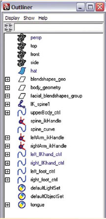
The new OUTLINER hierarchy after integrating the legs into the existing spine controls.
13. Save your scene file. Name your scene 06_asgn06.ma.
Assignment 6.7: Creating a Control System for the Eyes and Face
1. Open Maya and set your project.
a. From your computer’s desktop, go to [Start > Programs] and select Maya.
b. Once Maya is open go to [File > Project > Set…] and browse to your project folder then click “OK”.
2. Open your last saved file: Go to [File > Open] and select 06_asgn06.ma.
3. Turn X-ray Joints mode off by going to [Shading > X-ray Joints].
4. Make sure that your geometry layer is set to R for reference so that you are unable to select the geometry by mistake when working.
5. To make selection easier open your OUTLINER by going to [Windows > Outliner].
6. The eyes become part of the skeletal structure so that they move along with the skeleton, but do not deform. In the OUTLINER, select the right_eye_geo and left_eye_geo, then group them together by pressing (ctrl+g). Double-click on the group in the OUTLINER and rename the group eye_geo_group.
7. In the PERSPECTIVE view, with the eye_geo_group selected, shift select the headTip joint and press (p) to parent the eye_geo_group to the top joint in the head.
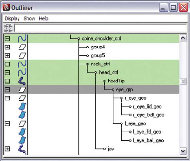
Parenting the Eye groups to the headTip joint.
8. Create a control system for the eyes by doing the following:
a. Go to [Create > NURBS Primitives > Circle].
b. In the channel box, rename nurbsCircle1 to eye_ctrl.
c. With the eye_ctrl selected set the following in the channel box: RotateX: type “90”.
d. In the FRONT orthographic with the eye_ctrl selected, select the move tool by pressing (w) and position the eye_ctrl in front of your character’s face.
e. In the PERSPECTIVE view, with the move tool, click on the Z axis (blue arrow) and move the controller in front of your character’s face, about half an arm’s length.
f. With the eye_ctrl selected, select the scale tool by pressing (r) and scale if necessary.

Creating and positioning the eye_ctrl.
g. Duplicate the eye_ctrl by going to [Edit > Duplicate] or press (ctrl+d).
h. In the channel box, rename eye_ctrl1 to left_eye_ctrl.
i. With the left_eye_ctrl selected, select the scale tool by pressing (r) and scale it smaller.
j. In the FRONT orthographic view, with the left_eye_ctrl selected, select the move tool by pressing (w) and position the left_eye_ctrl in front of the left_eye.
k. Duplicate the left_eye_ctrl by going to [Edit > Duplicate] or press (ctrl+d).
l. In the OUTLINER, double-click on left_eye_ctrl1 and rename it right_eye_ctrl.
m. In PERSPECTIVE view, select the move tool by pressing (w) and click on the X axis (red arrow), and position the right_eye_ctrl in front of the right_eye.
n. With the right_eye_ctrl selected, hold down the (shift) key and select left_eye_ctrl and eye_ctrl then go to [Modify > Freeze Transformations]. (To return both translate and rotate values to 0 and the scale values to 1.)
o. The rotation order does not need to be changed on these controllers, because rotations are not necessary for control.

Creating and positioning the left_eye_ctrl and the right_eye_ctrl.
p. In the OUTLINER, click on the left_eye_ctrl with the MMB and drag it onto the eye_ctrl. (This makes the left_eye_ctrl child to the eye_ctrl.)
q. In the OUTLINER, click on the right_eye_ctrl with the MMB and drag it onto the eye_ctrl. (This makes the right_eye_ctrl child to the eye_ctrl.)
r. In the OUTLINER, click on the eye_ctrl with the MMB and drag it onto the upperBody_ctrl. (This makes the eye_ctrl child to the upperBody_ctrl.)
s. In the PERSPECTIVE window, select the eye_ctrl, hold down the (shift) key, click the upperBody_ctrl and press (p) to parent. (Parenting the eye_ctrl to the upperBody_ctrl provides the ability to fix the character’s gaze in space. As another option, you could parent the eye_ctrl to the face_ctrl which is created next.)
9. Make the controllers function using Constraints by doing the following:
a. In the PERSPECTIVE window, click on the left_eye_ctrl (the leader), hold down the (ctrl) key, and click on the left eyeball_geo (the follower), then go to [Constrain > Aim – option box].
b. Place a check mark in the box next to Maintain Offset.
c. Then click “add”.
d. Repeat this for the right eye.
e. You can test the controls out by selecting them and moving them around in the PERSPECTIVE window.

Creating an aim constraint between the left_eye_ctrl (leader) and the left eyeball geometry (follower). Make sure the geometry is selected second to add the constraint correctly.
10. Create a control system for the facial expression by doing the following:
a. Go to [Create > NURBS Primitives > Circle].
b. In the channel box, rename nurbsCircle1 to face_ctrl.
c. With the face_ctrl selected set the following in the channel box: RotateX: type “90”.
d. In the PERSPECTIVE view panel, with the face_ctrl selected, select the move tool by pressing (w) and position the face_ctrl above your character’s head.
e. With the face_ctrl selected, select the scale tool by pressing (r) and scale if necessary.
f. The rotation order does not need to be changed on this controller, because rotations are not necessary for control.
g. In the PERSPECTIVE view, click on the face_ctrl, hold down the (shift) key, click on the head_ctrl, and then press (p) to parent. (This makes the face_ctrl child to the head_ctrl.)
h. With the face_ctrl selected go to [Modify > Freeze Transformations]. (To return both translate and rotate values to 0 and the scale values to 1.)

Creating and positioning the left_eye_ctrl and the right_eye_ctrl.
11. Add attributes to the face control to control the blend shapes by doing the following:
a. Select the face_ctrl and go to [Modify > Add Attribute] and enter the following:
i. Attribute name: type “leftEyeBlink”.
ii. Under Numeric Attribute Properties
1. Minimum: type “–10”.
2. Maximum: type “10”.
3. Click “Add”.
iii. Attribute name: type “rightEyeBlink”.
1. Minimum: type “–10”.
2. Maximum: type “10”.
3. Click “Add”.
iv. Attribute name: type “leftEyebrowRaise”
1. Minimum: type “–10”.
2. Maximum: type “10”.
3. Click “Add”.
v. Attribute name: type “rightEyebrowRaise”
1. Minimum: type “–10”.
2. Maximum: type “10”.
3. Click “Add”.
vi Attribute name: type “leftEyebrowFurrow”
1. Minimum: type “–10”.
2. Maximum: type “10”.
3. Click “Add”.
vii. Attribute name: type “rightEyebrowFurrow”
1. Minimum: type “–10”.
2. Maximum: type “10”.
3. Click “Add”.
viii. Attribute name: type “nose”
1. Minimum: type “–10”.
2. Maximum: type “10”.
3. Click “Add”.
ix. Attribute name: type “smileFrown”
1. Minimum: type “–10”.
2. Maximum: type “10”.
3. Click “Add”.
x. Attribute name: type “puckerWide”
1. Minimum: type “–10”.
2. Maximum: type “10”.
3. Click “Add”.
ix. Attribute name: type “mouthOpen”
1. Minimum: type “0”.
2. Maximum: type “10”.
3. Click “Add”.
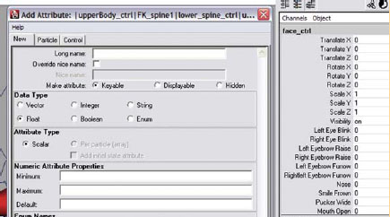
Adding custom attributes to the face_ctrl using [Modify > Add Attribute].
12. Before making the controls work, you must import your referenced model (at this point your model MUST be completed before importing). If you have not done so already, do the following:
a. Go to [File > Reference Editor].
b. Click on the file in the bottom half of the reference editor.
c. Go to [File > Import Objects from Reference].
13. Delete history on geometry that will be skinned. This should already be done, but it is a good idea to make sure that history is deleted on all skinable geometry. Go to [Edit > Delete by Type > Non Deformer History]. DO NOT DELETE HISTORY ON EYELIDS, as this will remove the makeNurbsSphere input, and the eye blinks will no longer work.
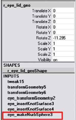
To verify that the INPUTS still exist on the eyelids, click on each eyelid and check the channel box.
14. Make sure blend shapes are applied by clicking on the base shape and checking the INPUT section of the channel box. If the blend shape input is not listed, then do the following:
a. Select your target shapes then shift select your base shape.
b. Select [Create Deformers > Blend Shapes].
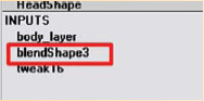
Verifying that the blend shape input still exist on the geometry base shape by checking the INPUTS in the channel box.
15. Make the leftEyeBlink attribute function using Set Driven Key by doing the following:
a. In the PERSPECTIVE window, select the left eyeball_geo. In the channel box, under the INPUTS section, click on makeNurbSphere, then go to [Animate > Set Driven Key > Set…].
b. Select the face_ctrl and click “Load Driver” in the Set Driven Key window.
i. In the Driver section of the Set Driven Key window, choose “leftEyeBlink” in the right column.
ii. In the Driven section of the Set Driven Key window, click on the makeNurbsSphere to select it.
![]()
If your eyelid does not have the input for makeNurbSphere1 you will need to recreate the eyes, or find an earlier version of your saved files and import those into this file.
iii. In the Driven section of the Set Driven Key window, in the right column choose “startSweep” then hold down the (ctrl) key and click on “endSweep”.
iv. In the Set Driven Key window, click “Key”. (This sets a default position of the leftEyeBlink value of “0”.)

Loading the Set Driven Key window and setting the first key so that when the leftEyeBlink attribute is set to “0”, the face is in the default (original) position.
v. In the Driver section of the Set Driven Key window, click on face_ctrl to select it.
vi. In the channel box, change leftEyeBlink to “10”.
vii. In the Driven section of the Set Driven Key window, click on makeNurbsSphere to select it.
viii. Change the start and end sweep to a closed position. In the channel box, change startSweep to about “0”, change endSweep to about “359.8”.
ix. In the Set Driven Key window, click “Key”.

Setting the second key so that when the leftEyeBlink is set to “10”, the left eye is blinking.
x. In the Driver section of the Set Driven Key window, click on face_ctrl to select it.
ix. In the channel box, change leftEyeBlink to “–10”.
xii. In the Driven section of the Set Driven Key window, click on makeNurbsSphere to select it.
xiii. Change the start and end sweep to a wide eyed position. In the channel box, change startSweep to about “70”, change endSweep to about “315” (these values could be more or less for your character).

Setting the third key so that when the leftEyeBlink is set to “–10”, the left eye is open wide.
xiv. In the Set Driven Key window, click “Key”.
c. Test the leftEyeBlink to make sure that it works properly.
i. In the Driver section of the Set Driven Key window, click on face_ctrl to select it.
ii. In the channel box, click on the words Left Eye Blink. Place your cursor in the PERSPECTIVE window, click and hold your MMB, and drag left to right to see the eye blink.
d. Repeat for the rightEyeBlink.
16. Make the leftEyebrowRaise attribute function using Set Driven Key by doing the following:
a. In the Driver section of the Set Driven Key window, choose “leftEyebrowRaise” in the right column.
b. Go to [Window > Animation Editors > Blend Shape] click on the “select” button in the blend shape window. Then click on “Load Driven” in the Set Driven Key window.
i. In the Driven section of the Set Driven Key window, in the right column choose “left_eyebrow_raise” then hold down the (ctrl) key and click on “left_squint”.
ii. In the Set Driven Key window, click “Key”. (This sets a default position of the leftEyebrowRaise value of “0”.)

Loading the Set Driven Key window and setting the first key so that when the leftEyebrowRaise attribute is set to “0”, the face is in the default (original) position.
iii. In the Driver section of the Set Driven Key window, click on face_ctrl to select it.
iv. In the channel box, change leftEyebrowRaise to “10”.
v. In the Driven section of the Set Driven Key window, click on blendShape1 to select it.
vi. In the channel box, change left_eyebrow_raise to “1”.
vii. In the Set Driven Key window, click “Key”.
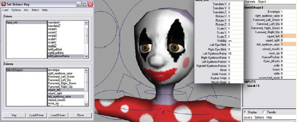
Setting the second key so that when the leftEyebrowRaise is set to “1”, the blend shapes cause the left eyebrow to raise.
viii. In the Driver section of the Set Driven Key window, click on face_ctrl to select it.
ix. In the channel box, change leftEyebrowRaise to “–10”.
x. In the Driven section of the Set Driven Key window, click on blendShape1 to select it.
ix. In the channel box, change left_ squint to “1”.
xii. In the Set Driven Key window, click “Key”.
xiii. Repeat these steps for the rightEyebrowRaise.

Setting the third key so that when the leftEyebrowRaise is set to “–1”, the blend shapes cause the eyes to squint.
17. Make the remaining attributes function using Set Driven Key the same way using the following as Driver and Driven:
a. Driver: face_ctrl : “leftEyebrowFurrow”.
b. Driven: blendShape1: “left_furrow_up” and “left_furrow_down”.
c. Driver: face_ctrl: “rightEyebrowFurrow”.
d. Driven: blendShape1: “right_furrow_up” and “right_furrow_down”.
e. Driver: face_ctrl: “nose”.
f. Driven: blendShape1: “scrunched_nose” and “nose_up (optional)”.
g. Driver: face_ctrl: “smileFrown”.
h. Driven: blendShape1: “smile” and “sad_frown”.
i. Driver: face_ctrl: “puckerWide”.
j. Driven: blendShape1: “narrow_pucker” and “wide”.
k. Driver: face_ctrl: “mouthOpen”.
l. Driven: blendShape1: “open”.
18. Save your scene file. Name your scene 06_asgn07.ma.
Assignment 6.8: Creating a Control System for the Tails, Ears, and Other Things That Move (Neckties)
Well congratulations, you have successfully learned many of the tools and techniques used to create a control rig for a 3D character. Depending on your design, however, you may still have a few body parts that need to be addressed. So here’s a chance to apply what you’ve learned.
If your character has ears, it is usually a good idea to add some type of joint system to control them. Ears can be a very expressive part of a character’s body and really helped an animator show great emotion from a character. Usually, three or four joints may be enough to create controls for short ears, but if the character has lengthy ones you may want to include a few more. Remember to check the local rotation axis and reorient the joints if necessary. You can use Set Driven Key or an IK chain with a controller to control the ear joints. Just make sure, if you’re using IK, to parent the ear controller to the existing head control. This way the ears won’t stick behind the character as he moves around.
Tails, antenna, and neckties can be easily controlled using the same system that we created for the spine. Usually the Spline IK creates a very fluid movement for long joint chains. Again, make sure the controllers for these body parts are parented to the existing control system. Tail controllers should be parented to the upper body control, antenna would most appropriately be parented to the head control, and a necktie of course would probably work best on the net control.
Whatever you are rigging, applying the tools that you’ve learned in this chapter can provide you with much of the control that will be needed when animating. This chapter has also provided you with a great foundation for learning more advanced techniques.