
OpenGL was designed to be the easily transportable standard high-end 3D graphics API for the next decade. OpenGL implementations exist for various X Windows, OS/2, Microsoft Windows 95 and NT implementations running on Sun, DEC, and SGI platforms. OpenGL provides a standard interface and standard functionality for rendering high-quality 3D graphics—a design intended to foster the acceptance of OpenGL across a wide variety of platforms, as well as to provide video board manufacturers with a well-defined collection of functionality on which to build graphics accelerators.
The predecessor to OpenGL was Silicon Graphics Incorporated’s (SGI) 3D graphics language, IRIS GL, designed for SGI’s IRIS line of graphics workstations. SGI was very successful in rapidly dominating the 3D graphics workstation market with a combination of fast hardware platforms and specialized video hardware that implemented many of the IRIS GL routines in the video hardware itself.
One of the deficiencies of Microsoft’s Windows platforms has always been their graphics capabilities, and 3D graphics in particular. With the advent of the 32-bit Microsoft Windows platforms, Microsoft got together with SGI, and they set about to create a hardware- and vendor-independent 3D graphics library that would bring the benefits of an IRIS GL–type library to platforms in addition to SGI’s. The benefits to Microsoft were to make Microsoft Windows a serious competitor for the workstation market, and for SGI it was a chance to expand into the PC marketplace.
Of course, Microsoft is hedging its bet with its purchase of RenderMorphics in February 1995. Thus Microsoft acquired the RenderMorphics Reality Lab—a 3D API designed for games—that is, a quick-and-dirty, graphics-object oriented library. However, most of the RenderMorphics API can be considered a superset of OpenGL’s, since they both have a vertex-based rendering engine. The polygon-and vertex-based Direct3DRM model requires the application to handle all of the scene management, without requiring a thorough knowledge of how 3D graphics work. It’s reasonable to assume that the video hardware manufacturers are working on the common features of the OpenGL/Direct3D API first. D3D is an API that is polygon- and vertex-based, and sounds a lot like OpenGL. Perhaps I’m biased, but I believe that given a choice between a high-level data-hiding API and a lower-level high-access to the underlying data API, graphics programmers will choose the low-level API, since getting as close to the metal as possible usually means getting the most speed possible.
My experience has been that the best graphics programmers usually go for the most flexible, most powerful interface, even if they end up having to do some things for themselves. Although Direct 3DRM may serve to boost the Windows games market and to drive the associated hardware, the applications that really stand out are those that push the envelope. Having absolute control over the scene management, the objects, the textures, the lighting, and so on seems like an excellent payoff for learning a new, complex interface, as opposed to a new, simpler one. You probably think so, too, or else you’d be reading something else!
Enough evangelizing—I’m starting to sound like a Microsoft employee. I don’t want to give the impression that you’ll have to go back to pixel-by-pixel programming. OpenGL is low level in the sense that it’s supposed to sit just above the hardware—it defines the API that the hardware (or, at worst, the emulation software) will provide. The advantage of OpenGL is in the higher-level functionality that it provides. Although it’s true that OpenGL is a low-level library, it’s a library for creating and rendering surfaces and objects. OpenGL gives you control over the object’s coloring, texturing, lighting, and shading. You get hidden-surface removal, modeling and viewing transformations, clipping and stenciling functionality, and object selection—all provided in an interface that can (and eventually will) be hardware resident. This is the dawn of a new age in personal computer programming. Not only our applications but also our very interfaces are going to become rich, textured things. The aesthetic appeal will be such a driving force that soon it will be as impossible to imagine using the flat Windows 3.1 interface as it is for a Mac user to imagine using the DOS prompt.
The OpenGL architecture is designed and maintained by the OpenGL Architecture Review Board. The Board, or “ARB,” is a collection of companies interested in seeing that a standard 3D architecture is provided across a variety of hardware platforms and operating systems. Two ARB members—Microsoft and SGI—have been working together on OpenGL since 1991.
The OpenGL standard is maintained by the ARB. Periodic revisions to OpenGL are made on the basis of requests from the OpenGL user community. The OpenGL features and the conformance tests are revised whenever a new version of the OpenGL standard is released. The conformance tests come into play when a vendor licenses OpenGL for a new platform. In order to be called OpenGL compliant, the vendor’s implementation must pass the conformance tests. These tests verify correct support for all the OpenGL features that the vendor has implemented. The vendor must implement a certain minimum set of OpenGL features and is free to choose which of the optional features or enhancements it wants to additionally implement. All of the features in the vendor’s implementation must pass the conformance tests, ensuring that all versions of OpenGL run code the same way on all platforms. Since OpenGL is designed to be exact in its rendering, a program running on an SGI Indigo workstation should produce nearly the same image, (in some cases pixel-for-pixel), given the same window size, as the program running on a Windows PC. The only differences should be the running time. In reality, an SGI workstation will probably have more features in its OpenGL implementation than a generic Windows implementation, but that hardware limitation can be fixed with the appropriate video hardware.
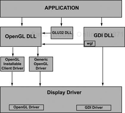
OpenGL works in much the same way that GDI works. It’s just an additional graphics layer that programs can address. GDI’s functionality resides in the GDI32.DLL (dynamic link library), which gets loaded whenever a program makes a GDI call. OpenGL is similar, in that whenever a program makes an OpenGL call, the OPENGL32 and GLU32 DLLs are loaded. Figure 3.1 shows how calls in an application program get processed on their way to becoming pixels on the screen. Windows NT maintains the client/server model that’ll be familiar to UNIX OpenGL programmers.
The OpenGL API found in Windows consists of about 150 functions in the API proper, some auxiliary functions, and some new Win32 functions designed to help set up a window for OpenGL rendering. Your particular implementation depends on any drivers that came with your video hardware and their configuration, since one of the benefits of OpenGL is that the hardware interface software can be custom tailored to your video card to provide maximum performance as well as expanded capabilities. Most of this will be almost totally hidden from view, although you should be aware that having a good video software/hardware combination is crucial to having optimized OpenGL performance on your system.
A vertex specified in OpenGL’s model coordinate system goes through quite a few steps before it turns up, if ever, as a pixel on your screen. Figure 3.2 diagrams the steps that a vertex goes through on its way to the screen buffer. A vertex is first run through the Modelview Matrix, which is a concatenation of the modeling and the viewing matrices (we’ll get into this in chapter 5). Basically these transformations turn the raw model coordinates—the ones that you use to construct your model—into coordinates located as they would be if viewed from that viewpoint.
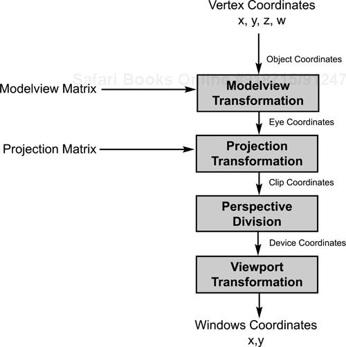
The next transformation is by the Projection Matrix, which allows OpenGL to then clip out vertices that are outside of the specified viewing volume. This is the point at which things that are out of view, or outside of the viewing volume (you specify a finite volume, not something stretching to infinity), are removed from consideration. At this point we have only those objects that are visible on the screen. We then apply the perspective division, which means that the w parameter is used to generate what’s called normalized device coordinates. Most of the time we leave w as 1, since you’d change it only under special circumstances. The final step is to apply the viewport transformation, which is where the 3D coordinates get turned into 2D framebuffer coordinates for eventual rendering on the screen or bitmap. In this step the depth buffer comes into play for hidden-surface removal.
You may be familiar with the Painter’s Algorithm for hidden-surface removal. This technique just draws everything, starting with the things in the back and ending up with the things in the front. The objects in the background get gradually obscured by things drawn in front of them. Although this method is very simple to implement, you still have to render everything in the scene (and rendering is a very expensive step), and you have to know about the geometry of the objects you’re rendering—a geometry that can’t be too complicated. The depth buffer takes care of this for you.
At this point in the rendering pipeline, we’re just about to render to the screen at a specific pixel location. The color of the object goes into the color buffer. The depth of the object—its distance from the viewpoint—goes into the depth, or z-buffer. If we’re drawing two objects that have some pixels that overlap, the first object will, after it’s rendered, have values in the color and depth buffers. When the next object is rendered, OpenGL will first check to see whether the pixel it’s about to draw is in front of (with respect to the viewpoint) any pixel from the first object that’s already been drawn. It does this by checking the z value of the current pixel with the value of the one already in the z-buffer at that particular location. If the new pixel is closer to the viewpoint, OpenGL places the new pixel’s color in the color buffer and its depth in the depth buffer. All this is done off in memory somewhere rather than checking the screen pixel, since nothing has been rendered yet; we try to avoid accessing screen memory whenever possible. Thus only those pixels that are in view are drawn, not entire objects. Although this may sound like a variation on the Painter’s Algorithm, the important difference is that we don’t render pixels that shouldn’t be rendered. It’s always faster to do some calculations than to draw things unnecessarily.
This technique of comparing buffer values to new pixel values is also used for other effects, such as stencil buffers and alpha accumulation values. A stencil buffer allows you to specify a stencil, such as the windows of a StarFighter cockpit, in which to render your OpenGL objects, thus leaving the interior of the cockpit alone. The alpha component is how we get translucency—the ability to see one object through another object. Unfortunately the alpha color component is ignored in the generic Windows 95 and NT OpenGL implementation, but you might have hardware that supports it. It works just like the depth buffer, except that if an object in the buffer is translucent but in front of the new pixel, the color of the pixel to be drawn is combined with the color of the pixel already in the color buffer, giving the effect of looking through the current object at an object behind it. In the generic implementation colors are always opaque, but when you see the effect of translucency, you’ll find the results stunning!
Figure 3.1 contains an area for an installable client driver. These drivers are hardware-specific methods of accelerating the rendering speed of applications, and are provided by the hardware manufacturers in order to take advantage of their video hardware. Just what capabilities are provided are up to the board manufacturer. It can be nothing at all or just GDI acceleration, if the board has no 3D-specific hardware; or just some OpenGL functions in hardware (the Mini Client Driver), up to a full-blown accelerated rendering pipeline that can offer performance orders of magnitude over generic implementation. Despite a lack of clear direction, the majority of board manufacturers seem determined to outdo one another. Standards for measuring OpenGL performance are still emerging, but soon we’ll be seeing boards that claim to be able to render so many tens of thousands of 25-pixel, anti-aliased, Gouraud-shaded, mipmapped, textured, lit triangles per second. The biggest advantage is that these will soon be the standard video boards found on PCs. Unlike the slow start on CD-ROMS or sound boards, which usually had to be an additional purchase before they became standard items, video boards are a given for all PCs.
A number of terms and phrases pop up frequently. So let’s quickly go over them so you’ll know what they mean when you see them.
Aliasing, antialiasing: When a line or a curve gets rasterized, you usually end up with a jagged, stepladder effect. That’s aliasing. Antialiasing is the effect of using partial pixel intensities to blur the jagged edges so that they appear to be smooth. As you might expect, antialiasing is computationally expensive. Aliasing effects decrease with higher-resolution screens, so if you’re considering turning antialiasing on, you might want to do this depending on the resolution of the screen your program’s currently running on.
Buffers: Computer memory is set aside for some purpose in buffers to denote color, z-value, stencils, textures, and so on. Generally the more and deeper the buffer, the better (and more expensive and slower to execute—all else being equal).
Depth: Depending on the context, this can refer either to a distance along the z-axis or, less restrictively, the distance away from the viewpoint or to the number of bits available in a buffer. For example, we can speak of depth of color (32K colors is deeper that 256 colors, that is, 15 bits deep as opposed to 8 bits) or of the z-buffer, in which case we’re referring to the magnitude of the values that can be stored. Depth is another word for granularity.
Lighting: This term refers to the effects of a light source on the colors that an object displays. These effects include ambient lighting, the omnidirectional light everywhere in a room; diffuse lighting, the lightening of surface colors due to a light source shining on the surface; and specular lighting, the effects of the “shininess” of a surface. Lighting and texture mapping are the two most important methods that OpenGL has for making rendered scenes appear rich and complex.
Matrix: Usually we mean a 4 ˘ 4 matrix that can perform scaling, rotation, and translation when applied to a vertex. OpenGL, however, also uses some internal matrices that we can access and modify.
Model, object: An object is usually a “piece” that’s generally rendered as an entity. A model is just a collection of objects that go together somehow. A car might be a model, made up of a body object, four wheel objects, and so on. Since OpenGL doesn’t have any native objects, this usually becomes a project-specific term. In this book it means whatever we happen to be rendering.
Normal, or surface normal: Given any plane, the surface normal is a vector that extends perpendicularly from the plane. This is used in lighting calculations to compute the angle at which light is reflected from the surface.
Plane: A mathematically flat surface, extending into infinity, a plane can also be thought of as a boundary used to define OpenGL’s viewing area and clipping effects. If you have three points in space that don’t coexist or lie on the same line, you can define a plane from them.
Polygon: Generally a polygon is a closed, flat surface bounded by three or more line segments. OpenGL has a slightly more restrictive definition for the polygons that it can render. See chapter 4. A polygon, the basic building block of OpenGL objects, is a flat, non-convex surface bounded by three or more vertices. You make everything out of these flat surfaces, usually ending up with hundreds or thousands of them (frequently machine or database generated, so don’t worry).
Primitive: Both native OpenGL primitives and user-defined primitives are any collection of polygons created as a whole. An object, on the other hand, is usually a collection of one or more primitives.
Quadrilateral: This term refers to a polygon of four sides, or a quad.
Rasterization: The last step in rendering is rasterization, the reduction of 3D primitives into 2D images.
Red Book, Blue Book: These are the standard OpenGL reference guides, the OpenGL Programming Guide, which has a red cover, and the OpenGL Reference Manual, which has a blue cover, respectively. The Microsoft online documentation has excerpts from these books, but by themselves the books are invaluable resources for both the novice and the expert OpenGL programmer. See the bibliography at the end of this book.
Rendering: This is the process of taking one or more objects specified in an abstract object model and turning them into shaded, textured, illuminated objects in a raster image. By contrast, drawing means writing directly to the raster image. If you want to change the scene in 3D graphics, you change the objects and let the rendering process draw the results.
Shading: This is the interpolation of color (usually after lighting effects have been calculated) across an object, usually from the vertices. OpenGL supports two shading models. Flat shading uses only one vertex to calculate shading for the entire polygon, which sometimes results in each polygon standing out from its neighbors (but it’s fast!). Smooth shading, which in OpenGL is called Gouraud shading (rhymes with Thoreau), linearly interpolates the lighting effects from each vertex. It looks great but is computationally expensive. Another popular interpolation method, called Phong shading, achieves even better results but was deemed too computationally expensive for the initial release of OpenGL.
State machine: OpenGL is a state machine; you change a current parameter by direct action—setting the color, for example. That state remains in effect until it’s changed. This means that your program has to be state-aware.
Tessellate: This refers to the act of decomposing a complicated, usually curved, surface into a collection of simpler shapes, the objective being to simplify rendering those shapes. Sometimes done with pencil and paper, tessellation is more frequently done by handing a description of a curved or complicated surface to a function that breaks the surface down into component polygons.
Texture mapping: The effect of applying a texture bitmap, usually a 2D bitmap, onto a 3D object is to give the appearance of having a highly textured surface, like painting a picture on the surface. Texture mapping is a highly efficient way to give a realistic look to an otherwise simple object. A picture of a building placed onto a square makes the square look like a building, and it’s a heck of a lot faster to render than all those door and window objects if you added them to your model.
Transformation: OpenGL has many transformation steps, or the mathematical act of applying some form of scaling, rotation, or translation. Transformation involves going from model coordinates to viewing coordinates, through projection, and on to rasterization. Transformation generally means that we’re applying some matrix calculations to our model’s vertices to get them into another state.
Vertex: In this book the term vertex of a polygon refers to the intersection of two edges—the corner of a polygon. I’ll be referring to a vertex as either a particular corner of an object or the location of that corner as a two-, three-, or four-element coordinate. All objects, at their lowest level, are defined by their vertices.
Windows, windows: In this book Windows refers to Microsoft Windows—either Windows NT or Windows 95—unless specifically noted. The term windows, on the other hand, refers to an on-screen window, the kind that the operating system opens up and that we render to.
Programming OpenGL usually means creating some type of primitive. Most of the examples in the next section will be using OpenGL commands that are new to you, simply because you need to make a variety of OpenGL calls before anything can be seen on the screen. This section is a quick introduction to the basics of OpenGL commands and how to set up for and describe vertices.
In order to further optimize the rendering of primitives, OpenGL restricts the time that you can describe primitives to be wrappered between two calls to the API, glBegin() and glEnd(). This is similar to the Windows requirement of wrappering drawing code with a fetch and release of a DC (drawing context) when preparing to draw to a window. All OpenGL descriptions of primitives start with glBegin(xxx), where xxx is an OpenGL-defined constant that identifies the OpenGL primitive you’re about to describe. In order to further simplify the API interface, only a restricted set of OpenGL functions may be called between a glBegin()/glEnd() pair. These calls are the ones that describe vertices or their attributes.
OpenGL has an abundance of function calls that differ only in the type of arguments they take. These functions result in the same commands being executed but with a variety of ways of initiating the function call. (Remember, this is a C interface, not a C++ one!) Following with the tradition started in the Red and Blue Books, I’ll use a generic notation for those calls that have multiple formats. For example:
void glSomeFunction{3}{bsifd}{v}(arguments);The first optional term in curly braces indicates that this particular function is the one that takes three arguments. Some groups of functions take two, three, and four arguments. The second set of braces indicates that this function can take five (of eight) possible argument types: b = byte, s = short, i = integer, f = float, d = double. The last term in curly braces indicates that a vector form of the command also exists. Instead of passing in the required number of parameters, in this case you’d pass in a vector containing the proper amount. Thus the following commands for describing a 3D vertex are all functionally equivalent:
GLdouble v[3] = { 1.0, 2.0, 3.0 }; // create a vector

glVertex3i(1,2,3); // ints
glVertex3f(1.0f,2.0f,3.0f); // floats
glVertex3d(1.0,2.0,3.0); // doubles
glVertex3dv( v ); // the 3 element double vector
Rather than type in function calls with items in curly braces, any function being generically talked about in the text but having a multitude of interface formats will be referenced as glSomeFunction*(), so don’t be confused when you see this; it’s just a reminder that there are many ways to call this function.
As we’ve seen, the glVertex*( ) function is used to construct a primitive in OpenGL. The arguments are the vertex’s x, y, and (optionally) z, and w coordinates. We’ll be using the two-argument and three-argument forms for most of the book. The two-argument form uses z = 0, placing the vertices on the x-y plane. The three-argument form accepts a z coordinate. The fourth argument, the w parameter, allows you to play with the normalized coordinate values. Generally we just leave this as a value of 1.0 and ignore it. The full format of all the 2D and 3D versions of the glVertex*() command are listed next; as you can see, we save a lot to space by using the generic format.
glVertex2s( GLshort, GLshort ); // two shorts
glVertex2i( GLint, GLint ); // two ints
glVertex2f( GLfloat, GLfloat ); // two floats
glVertex2d( GLdouble, GLdouble ); // two doubles
glVertex2sv( GLshort[] ); // vector of two shorts
glVertex2iv( GLint[] ); // vector of two ints
glVertex2fv( GLfloat[] ); // vector of two floats
glVertex2dv( GLdouble[] ); // vector of two doubles

glVertex3s( GLshort, GLshort, GLshort ); // three shorts
glVertex3i( GLint, GLint, GLint ); // three ints
glVertex3f( GLfloat, GLfloat, GLfloat ); // three floats
glVertex3D(GLdouble, GLdouble, GLdouble ); // three doubles
glVertex3sv( GLshort[] ); // vector of three shorts
glVertex3iv( GLint[] ); // vector of three ints
glVertex3fv( GLfloat[] ); // vector of three floats
glVertex3dv( GLdouble[] ); // vector of three doubles
How does all this functionality become available? There are two ways that OpenGL might be on your system. If you have Microsoft Windows NT 3.5 or later, or you’ve recently obtained Windows 95 on a new machine then you’re all set—all the functionality is already in your system. OpenGL is part of Windows NT, and beginning in late 1996, machines that come with Windows 95 will come with OpenGL installed. Be aware, though, that prior to the release of Windows NT 4.0, there were different versions of OpenGL floating around. Windows NT 3.51 had an updated version of OpenGL from NT 3.5, and Microsoft made a set of DLLs available for Windows 95. You should have your programs carefully check out the current system’s capabilities before making any assumptions about the capabilities of the version of OpenGL they are running. If you are running an early version of Windows 95 and don’t have the OpenGL DLLs, you can either use the DLLs on the CD-ROM that came with this book, or you can check the online resource listed in chapter 12 for the latest versions.
OpenGL is made available in your system through a system DLL. A DLL, or dynamic-link-library, is a library that resides separately from your program but is an integral part of it. At program run time the operating system will load the DLLs your program requires. One advantage of the DLL system is that your executable is smaller and faster to load, especially if other programs already have the DLLs loaded for you, since DLLs are loaded only once and then shared. The biggest advantage is that by using a DLL, you’ll get the benefit whenever any other program or new operating system brings in an updated DLL. For example, when Microsoft released OpenGL 1.1 with its speed enhancements, any program that used only OpenGL 1.0 features will still benefit from the improvements in OpenGL 1.1. This will be just as true when some future OpenGL version 6.0 becomes available.
On Microsoft Windows platforms the main library is the opengl32.dll. This library is the main repository of all the gl*() routines. If your program uses nothing more than the main OpenGL routines, this is the only library you’ll need to link to.
The utility library—glu32.dll—is the repository of all the glu*() routines. The utility routines contain several collections of commands that complement the main OpenGL routines. These commands provide such things as rendering spheres and other geometric shapes, manipulating bitmaps, performing surface tessellation, creating projection matrices, and handling errors. The utility library is considered part of a standard OpenGL implementation.
The auxiliary library, glaux.lib, is only a library, since it’s a system-dependant wrapper about some of the operating system. As the repository of all the aux*() routines, the auxiliary library is not an official part of OpenGL per se. However, it’s such a valuable learning aid that it accompanies most, if not all, OpenGL implementations. The auxiliary library is designed to insulate you from having to know much about the windowing system that you’re experimenting on. You can use the auxiliary library to create an entire, running OpenGL program that can react to mouse and keyboard events with fewer than fifty lines of code. Of course, it won’t be able to do a whole lot with such insulation from the operating system. However, it’s very useful for examining the behavior of OpenGL commands without having to worry about getting a framework set up beforehand.
The source code for this library is distributed as part of the WIN32 SDK and the Microsoft Developer Network (MSDN) Level 2 membership. If you examine the source code, you’ll readily find evidence of an even earlier toolkit, called the TK toolkit, which was originally part of the OpenGL toolkit found on X Windows systems. Examining the sources for the AUX library, the other OpenGL examples found on the MSDN CD, and the sources that accompanied your compiler is a good way to see how OpenGL programs are written and to get an idea of other things that you can do with OpenGL.
Installing OpenGL on Windows 95 is straightforward. If you have an early release of Windows 95 and don’t have the glu32.dll or the opengl32.dll on your system, simply copy them to the system subdirectory of your Windows directory. That’s all.
Learning OpenGL is a lot like learning a new programming language; you can get as much out of it as you care to invest. I don’t want to give you the impression that OpenGL is particularly easy—it is easy. It just does complicated things that sometimes require some head scratching to figure out. And of course the advanced features will require some thought before you can use them, but that’s true of any powerful language.
The nice thing about OpenGL is that it’s pretty easy to get started with, building up your knowledge to a point where you’re ready to take on something more complex. I find that when I have a new toy, such as the Visual C++ updates I seem to keep getting, I’ll peruse the manual, looking for new things or things that I don’t know much about yet. I find that frequently I’ll run across some problem or implementation that will tickle the back of my mind and something I’ll have read will pop up, and I’ll have a flash of insight into how to use some feature I haven’t tried yet.
OpenGL is conducive to this method of learning, since you can always achieve some effect you thought was impossible, just by applying a feature that you don’t know or haven’t thought much about. And the best way of learning is to jump right in and start programming!
The next chapter will cover all the necessary but boring details of implementing OpenGL on a Windows platform. Then you’ll be ready to start writing your own OpenGL programs.