Timber frame is the second most popular construction method for homes in England and Wales, with 15% of UK housing output. It is the most popular in Scotland with 75% of market share.6 There are different types but they all use a timber frame as structural support, timber sheathing and insulation between or outside timber studs. Timber frame is best suited to low-rise development of one to four storeys, but solid timber panels and engineered timber can be used to build apartments up to 10 storeys. A vapour barrier is required to prevent moisture entering the wall structure from the inside. A breather membrane is required to protect against external moisture and an outer leaf of cladding protects from weather and solar radiation.
The timber frame is usually manufactured off-site to different levels of completion – either as an open or closed panel. The panels are taken to site and erected by the supplier or sub-contractor. Some contractors and sites will favour ‘stick construction’ over prefabricated panels, but off-site manufacture of panels or modules can enable better performance.
There are a wide range of types of timber frame, with different types of insulation, moisture barrier, airtightness and erection methods.
The typical methods are shown in Figure 5.1, below.
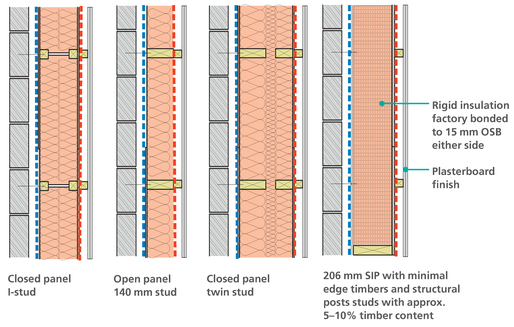
Figure 5.1
Different types of timber frame construction.
Summary
Advantages
- » Fast speed of construction, typically 20–30% quicker than masonry.
- » Ability to easily monitor insulation and airtightness membranes.
- » Flexible aesthetics with different external claddings possible.
- » Good airtightness achievable with membrane or ply board.
- » Good thermal performance as timber has lower conductivity than masonry.
- » Timber is a renewable material and can be reused following demolition.
Disadvantages
- » Thermal performance and timber fraction is often estimated at design stage and timber and steel content is often higher in reality.
- » Lightweight construction means it is hard to integrate exposed thermal mass, so it is vulnerable to overheating.
- » Timber easily absorbs water and deforms, so must be kept dry during construction.
- » Differential movement between timber and masonry / windows can lead to poor construction accuracy.
Recommendations
- » Consider prefabricated panels that minimise site work.
- » Timber frame must be at least 150 mm above ground level (NHBC).
- » Select insulation that will not allow air gaps.
- » Design so timber does not bridge the whole of the insulation zone.
- » Specify steel web floors to allow service zone.
- » Consider I-beam or twin stud wall to minimise thermal bridging of solid timber.
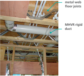
Figure 5.3
Masonry floor and upstand commonly used in timber frame construction (right).
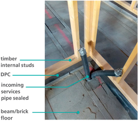
Figure 5.2
Steel web timber joist floor creates service zone (left).
Common Problems
- » Timber and steel content of construction is often not known at design stage, so thermal performance is often worse.
- » Without a service zone, the VCL is vulnerable to damage, causing poor airtightness and condensation issues.
- » Rigid insulation in between timber studs is difficult to fit accurately without gaps.

Figure 5.4
Excessive timber and steel content compromises thermal performance.

Figure 5.5
VCL is penetrated by incoming services.
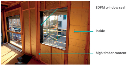
Figure 5.6
Rigid insulation in between timber studs is difficult to fit accurately without gaps.
Good Practice
Timber is approximately five times more conductive than insulation, so more timber results in poor thermal performance. Figure 5.7 demonstrates how an extra layer of insulation should be installed inside or outside the frame to minimise thermal bridging.
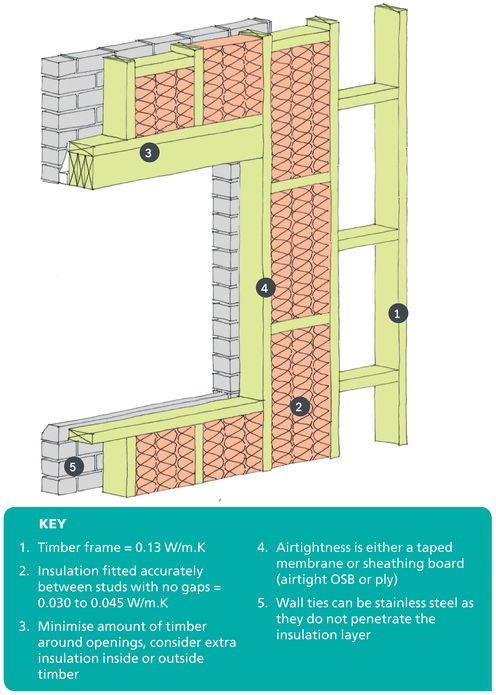
Figure 5.7
3d drawing showing typical timber frame construction and the need to install extra insulation layer in order to minimise thermal bridging.
Details
The rest of this chapter highlights good practice detailing for timber frame with emphasis on thermal performance. The location of these junctions are shown in this section drawing through a typical house. The most significant external envelope details affecting heat demand are drawn with good practice airtightness and continuous insulation where practical. Heat loss is calculated and psi-values provided where useful for SAP calculations.

Detail 5.1 Level Threshold
The door must line up with the insulation underneath and timber frame insulation in the adjoining wall. The screed acts as the airtightness in the floor which is taped to the door frame.

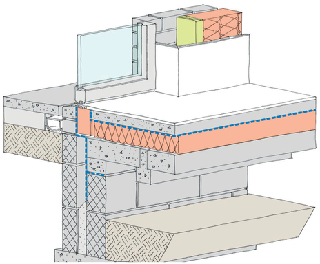
Figure 5.8
3D illustration of level threshold showing structural insulation (e.g. Foamglas) under door frame.
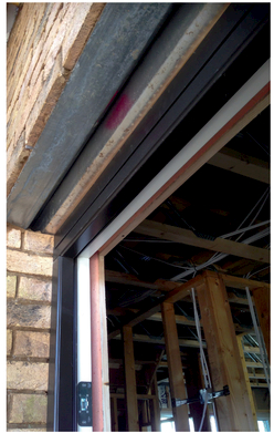
Figure 5.9
Door frame and lintel (left).
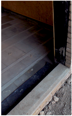
Figure 5.10
Door level threshold (right).
Detail 5.2 Intermediate Floor
Ensure the ends of floor joists are fully insulated and airtight with the correct sequencing. Thermal bridging can be reduced by adding an extra layer of insulation to the outside of the timber frame.

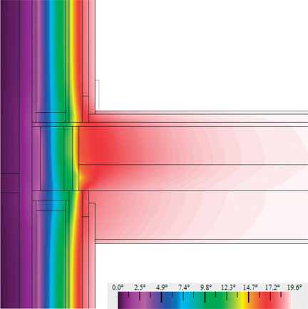
Figure 5.11
Heat flux diagram corresponding to Detail 5.2 (opposite).
Heat flux diagram and psi-value
This heat flux diagram shows heat flow through the external wall at intermediate floor level (see Detail 5.2). This is normally an area of significant heat loss, and so the design must allow for insulation in the floor cassette or externally to prevent thermal bridging. This detail has a psi-value of 0.067 W/m.K, which is a 52% reduction in heat loss compared to the default value of 0.14 W/m.K.
The temperature factor is above the critical value of 0.75, and so there is no risk of condensation or mould growth. Please refer to Appendix 3 for further information.
| SAP Appendix K Reference | E7 |
|---|---|
| psi-value | 0.067 W/m.K |
| temperature factor | fRsi = 0.94 |
| approved value | 0.07 W/m.K |
| default value | 0.14 W/m.K |
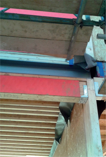
Figure 5.12
Intermediate floor timber cassette (left).

Figure 5.13
Internal view of intermediate floor - I joists (right).
Detail 5.3 Party Wall
Thermal and acoustic performance must be considered in a party wall, so non rigid insulation is preferable. An additional service zone could be added to improve airtightness which improves both acoustic and thermal performance.

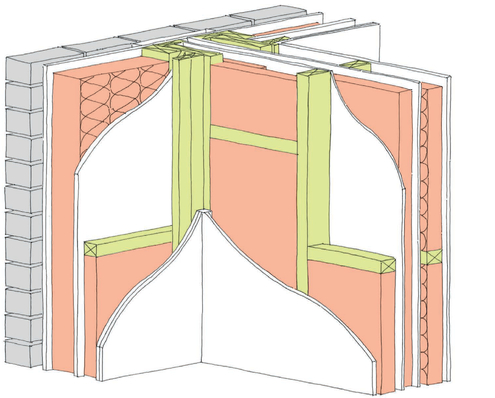
Figure 5.14
3D illustration of the external wall and party wall junction showing the importance of specifying full fill insulation for thermal and acoustic performance.

Figure 5.15
Party wall construction (left).
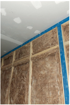
Figure 5.16
Airtightness tape sealing junctions (right).
Detail 5.4 Window Detail
There are three psi-values that should be calculated for a window: the jamb, cill and lintel. There are significant reductions in heat loss when the psi-value is calculated for each detail. Insulating the window reveal results in a significant improvement in the thermal performance. Moving the window in line with the SIP panel will further improve thermal performance.

Psi-value
The three psi-values that account for the performance of the window junctions in this case are significantly better than the default value.
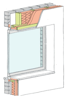
Figure 5.17
3D illustration of the window installation.
| SAP Appendix K Reference | E2 Lintel | E3 Sill | E4 Jamb |
|---|---|---|---|
| psi-value | 0.069 W/m.K | 0.028 W/m.K | 0.067 W/m.K |
| temperature factor | fRsi = 0.92 | fRsi = 0.92 | fRsi= 0.91 |
| approved value | 0.3 W/m.K | 0.04 W/m.K | 0.05 W/m.K |
| default value | 1.0 W/m.K | 0.08 W/m.K | 0.1 W/m.K |
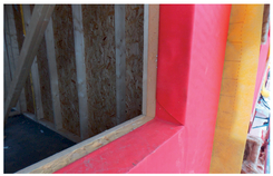
Figure 5.18
SIP window opening from outside (top left).
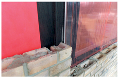
Figure 5.19
EPDM seal adhered to red breather membrane (top right).
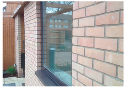
Figure 5.20
Complete window from outside (bottom left).

Figure 5.21
Window opening from inside (bottom right).
Detail 5.5 Recessed Door
Canopies over doors often require additional structural steel which needs to be properly insulated or thermally separate from the thermal envelope. Recessed doors are a point of increased heat loss area and are difficult to insulate. Ensure adequate insulation and sequencing is agreed to achieve performance.


Figure 5.22
Heat flux diagram corresponding to Detail 5.5 (opposite).
Heat flux diagram and psi-value
This heat flux diagram shows heat flow through a recessed external door junction. This is normally an area of significant heat loss and so the design must allow for insulation in the floor cassette to prevent thermal bridging. This detail has a psi-value of 0.071 W/m.K, which is a 78% reduction in heat loss compared to the default value of 0.32 W/m.K.
| SAP Appendix K Reference | E20 |
|---|---|
| psi-value | 0.071 W/m.K |
| temperature factor | fRsi = 0.88 |
| approved value | N/A |
| default value | 0.32 W/m.K |

Figure 5.23
Recessed entrance with double steel lintel (left).
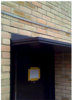
Figure 5.24
Canopy installed above door with thermally separate structure (right).
Detail 5.6 Flat Roof
Continuous insulation around a timber frame is important to ensure no thermal bridging through the timber.

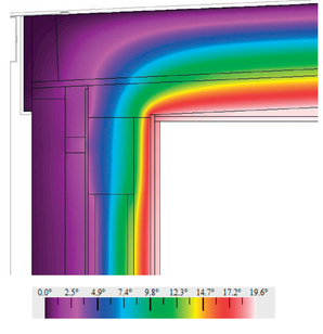
Figure 5.25
Heat flux diagram corresponding to Detail 5.6 (opposite).
Heat flux diagram and psi-value
This heat flux diagram shows heat flow through the flat roof and external wall junction. The top of the wall has a significant amount of timber for structural reasons, which increases the heat loss. The internal insulation has reduced the amount of heat loss to improve on the default. This detail has a psi-value of 0.062 W/m.K, which is 22% better than the default value of 0.08 W/m.K.
The temperature factor is above the critical value of 0.75, and so there is no risk of condensation or mould growth.
| SAP Appendix K Reference | E14 |
|---|---|
| psi-value | 0.062 W/m.K |
| temperature factor | fRsi = 0.95 |
| approved value | N/A |
| default value | 0.08 W/m.K |
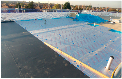
Figure 5.26
Layers of construction on timber flat roof.