Off-site manufacture of building elements, rooms or whole buildings becomes more attractive as traditional construction gets more expensive and demand outstrips supply. There is a range of off-site construction types, broadly split into three categories:
These three types can be used in combination with each other and so various hybrid systems can be used like CLT volumetric or SIPs with a concrete frame. They all require an element of standardisation of the design and require the designer to work with the manufacturer at an early stage to understand the requirements of each system. Previous chapters have examined SIPs and CLT panelised construction, so this chapter looks at the volumetric approach. The most common approach for volumetric is to construct the modules with a steel frame with insulated timber infill panels. Steel frame volumetric has some structural benefits, but the steel frame has high thermal conductivity, and so generally does not perform as well as a timber volumetric solution. Any steel structure needs to be fully insulated inside the thermal envelope or fully separated so no thermal bridging occurs. Timber frame has structural span and height limitations, and so CLT is recommended as an optimum solution for volumetric. This chapter provides some key details for volumetric CLT construction.

Figure 7.1
Elemental – bathroom, kitchen, services pods. etc. (left).

Figure 7.2
Panelised – timber SIPS, timber panels, CLT, pre-cast concrete panels (centre).

Figure 7.3
Volumetric – steel/ timber, CLT, timber (right).
Summary
Advantages
- » Construction of modules in factory allows for better quality assurance.
- » Excellent airtightness potential.
- » Excellent thermal continuity.
- » Fast construction on site – typically 70% less time on site compared with masonry (NAO 2005).
- » Steel or timber structure is possible.
- » Reduced damage and waste of materials.
- » Better working conditions: weather, access, stability and safety.
- » Can be delivered in a range of aesthetics to be indistinguishable from traditional housing.
Disadvantages
- » Designing for modules to fit on a lorry can be restrictive.
- » Requires greater investment and coordination up front.
- » Coordinatation and design work is needed much earlier.
- » Overhead costs of factory production means a consistent supply / demand of housing is preferable to keep cost per dwelling down.
- » The quality, performance and aesthetics of modular construction can vary.
Recommendations
- » Check the detailed design of the volumetric system to ensure it does not have significant thermal bridges caused by excess steelwork.
- » Consider timber structures like CLT for modular construction that can provide continuous thermal performance without a steel structure.
- » Design using the standard dimensions and spans of the modules, or agree variations and capabilities with manufacturer.
- » Ensure coordination with services is done up front so it can ‘plug and play’ once on site.
- » Designers should work with the manufacturer early on to understand opportunites and limitations in order to improve the design for better performance.
Good practice
This chapter illustrates some good practice CLT detailing used on construction projects For more information, please refer to technical bulletins available from the Structural Timber Association.8


Figure 7.4
CLT provides an airtight structure to be taped at junctions (below left).

Figure 7.5
CLT must be carefully coordinated with services before construction (below centre).

Figure 7.6
CLT is vulnerable to moisture and so needs to have a concrete or masonry upstand and other significant damp-proof detailing (below right).
Detail 7.1 Separating Floor
Thermal insulation must be co-ordinated around the fire barrier and damp proof course, and installed tightly up against it with no gaps.
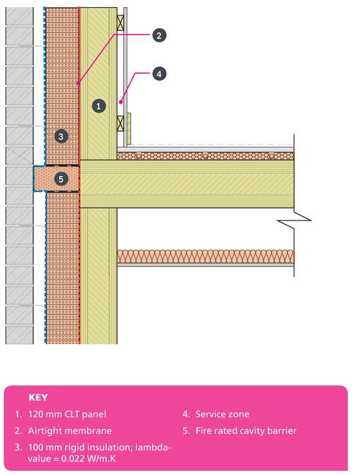

Figure 7.7
Heat flux diagram corresponding to Detail 7.1 (opposite).
Heat flux diagram and psi-value
This heat flux diagram of the external wall and intermediate floor junction shows the importance of continuous external insulation and heat loss that is possible through a timber floor even when it is well insulated. The psi-value for this detail is 0.082W/m.K, which is a 41% reduction in heat loss compared to the default value of 0.14 W/m.K. The temperature factor is above the critical value of 0.75, and so there is no risk of condensation or mould growth. Please refer to Appendix 3 for further information.
| SAP Appendix K Reference | E7 |
|---|---|
| psi-value | 0.082W/m.K |
| temperature factor | fRsi = 0.96 |
| approved value | 0.07 |
| default value | 0.14 W/m.K |
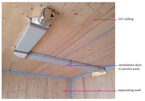
Figure 7.8
CLT separating floor with service zone.
Detail 7.2 Window
The window should be installed in line with the insulation layer to reduce thermal bridging. A half brick reveal would be easier to construct and have improved thermal performance.
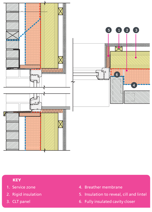

Figure 7.9
3D illustration of the window installation with CLT. The window should be taped to the CLT to provide a robust airtight layer.
Psi value
The three psi-values calculated all show significant improvements over the default value, e.g. the lintel shows a 99% reduction in heat loss.
Insulated window reveals and thermally separate lintel contribute to the lower psi-value and reduction in heat loss.
| SAP Appendix K Reference | E2 lintel | E3 sill | E4 jamb |
|---|---|---|---|
| psi-value | 0.009W/m.K | 0.005 W/m.K | 0.029 W/m.K |
| temperature factor | fRsi = 0.97 | fRsi = 0.96 | fRsi= 0.97 |
| approved value | 0.3 W/m.K | 0.04 W/m.K | 0.05 W/m.K |
| default value | 1.0 W/m.K | 0.08 W/m.K | 0.1 W/m.K |
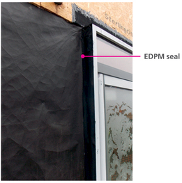
Figure 7.10
Window head and jamb with cavity closer and thermally separate lintel (left).
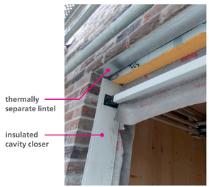
Figure 7.11
Window installed in CLT with EPDM seal, before insulation and brickwork are installed (right).
Detail 7.3 Parapet
Wrapping the parapet in insulation significantly reduces heat loss.

Psi-value
The psi-value for this detail is 0.054W/m.K, which is a 90% reduction in heat loss compared to the default value of 0.56 W/m.K. The temperature factor is above the critical value of 0.75, and so there is no risk of condensation or mould growth. An inverted roof is an alternative construction, but the insulation does not perform as well when it is wet. A warm roof like this will keep the insulation dry and improve performance.
| SAP Appendix K Reference | E15 |
|---|---|
| psi-value | 0.054 W/m.K |
| temperature factor | fRsi = 0.92 |
| approved value | N/A |
| default value | 0.56 W/m.K |
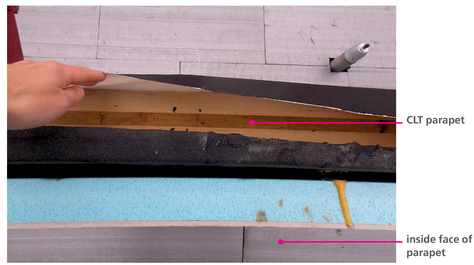
Figure 7.12
Insulation and DPM lining the inside of CLT parapet.
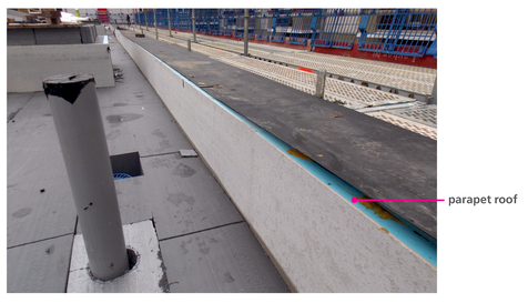
Figure 7.13
Flat roof with tight services penetrations.
Detail 7.4 Eaves
Continuous insulation and airtightness should be achieved at the roof and wall junction. An airtight breather membrane should be taped at junctions and coordinated with fire rated cavity barrier.


Figure 7.14
Heat flux diagram corresponding to Detail 7.4 (opposite).
Heat flux diagram and psi- value
This heat flux diagram of the external wall and eaves junction shows the improvement in performance when continuous external insulation is achieved. Heat loss is significantly reduced when continuous insulation can be achieved. The psi-value for this detail is 0.012 W/m.K, which is an 85% reduction in heat loss compared to the default value of 0.08 W/m.K.
The temperature factor is above the critical value of 0.75, and so there is no risk of condensation or mould growth. Please refer to Appendix 3 for further information.
| SAP Appendix K Reference | E11 |
|---|---|
| psi-value | 0.012 W/m.K |
| temperature factor | fRsi = 0.96 |
| approved value | 0.04 W/m.K |
| default value | 0.08 W/m.K |

Figure 7.15
3D illustration of this eaves detail.