1
Thermodynamic Systems
1.1 Overview
Thermodynamics is the science relating heat and work transfers and the associated changes in the properties of the working substance within a predefined working system. A thermodynamic system is one that is concerned with the generation of heat and/or work using a working fluid. In this chapter, thermodynamic system behaviour will be described and the changes in properties will be calculated during the different processes encountered in typical engineering applications.
Learning Outcomes
- To understand the basic units and properties of thermodynamic systems.
- To be able to apply the laws of thermodynamics to closed and open systems.
- To be able to apply the first law of thermodynamics and calculate the changes in properties during a process and a cycle.
- To be able to solve problems related to compression and expansion of steam and gases.
1.2 Thermodynamic System Definitions
A thermodynamic system comprises an amount of matter enclosed within a boundary separating it from the outside surroundings.
There are two types of thermodynamic system:
- A closed system has a fixed mass and a flexible boundary.
- An open system has a variable mass (or mass flow) and a fixed boundary.
1.3 Thermodynamic Properties
A thermodynamic property of a substance refers to any quantity whose changes are defined only by the end states and by the process. Examples are the pressure, volume and temperature of the working fluid in the system in Figure 1.1. In addition to these three properties, other thermodynamic properties include enthalpy, entropy and internal energy, which are all important in studying the behaviour of the working fluid in a power plant.

Figure 1.1 Thermodynamic system, boundary and surroundings.
A list of the most common properties and associated terms is given below:
- Pressure (P) – The normal force exerted per unit area of the surface within the system. For engineering work, pressures are often measured with respect to atmospheric pressure rather than with respect to absolute vacuum. If a pressure gauge is calibrated to read zero at atmospheric pressure then the absolute pressure (Pabs) is given by:

In SI units, the derived unit for pressure is the pascal (Pa), where 1 Pa = 1 N/m2. This is very small for engineering purposes, so usually pressures are quoted in terms of kilopascals (1 kPa = 103 Pa), megapascals (1 MPa = 106 Pa) or bars (1 bar = 105 Pa).
- Specific volume (v) – For a system, the specific volume is the space occupied by a unit mass. The units of the specific volume are therefore m3/kg. (Note that the term specific and lower‐case letters are commonly used to denote thermodynamic property values per kg of substance.)
- Temperature (T) – Temperature is the degree of hotness or coldness of the system or the working fluid contained in the system. The absolute temperature of a body is defined relative to the temperature of ice at 0 °C. In SI units, the Kelvin scale is used, where 0 °C ≡ 273.15 K.
- Specific internal energy (u) – The property of a system covering all forms of energy arising from the internal structure of its matter, for example, nuclear, molecular, vibrational etc. The units of specific internal energy are kJ/kg.
- Specific enthalpy (h) – An energy property of the system conveniently defined as the sum of the internal energy and flow work, i.e. h = u + PV for a substance. The units of specific enthalpy are kJ/kg.
- Specific entropy (s) – Entropy refers to the microscopic disorder of the system. It represents the effect of irreversibilities due to friction and deviation from the ideal behaviour. Ideal processes are termed isentropic. The units of specific entropy are kJ/kg K.
- Phase– The condition of a substance described by terms such as solid, liquid or gas is known as its phase. Phase change occurs at constant temperature. Phase changes are described as follows:
- Condensation: gas (or vapour) to liquid
- Evaporation: liquid to gas (or vapour)
- Melting: solid to liquid
- Freezing: liquid to solid
- Sublimation: solid to gas
- Deposition: gas to solid.
- Mixed phase – A multi‐phase condition, for example, ice + water, water + vapour etc.
- Quality of a mixed phase or dryness fraction (x) – The dryness fraction (no units, values 0–1) is defined as the ratio of the mass of pure vapour present to the total mass of a mixed phase. The quality of a mixed phase may be defined as the percentage dryness of the mixture.
- Saturated state – A saturated liquid is a state in which the dryness fraction is equal to zero. A saturated vapour has a quality of 100% or a dryness fraction of one.
- Pure substance – A pure substance is one which is homogeneous and chemically stable. Thus, it can be a single substance that is present in more than one phase, for example, liquid water and water vapour contained in a boiler (in the absence of any air or dissolved gases).
- Triple point – A state point in which all solid, liquid and vapour phases coexist in equilibrium.
- Critical point – A state point at and above which transitions between liquid and vapour phases are not clear.
- Superheated vapour – A gas is described as superheated when its temperature at a given pressure is greater than the phase change (or saturated) temperature at that pressure, i.e. the gas has been heated beyond its saturation temperature. The degree of superheat represents the difference between the actual temperature of a given vapour and the saturation temperature of the vapour at a given pressure.
- Subcooled liquid (or compressed liquid) – A liquid is described as undercooled or subcooled when its temperature at a given pressure is lower than the saturated temperature at that pressure, i.e. the liquid has been cooled below its saturation temperature. The degree of subcool represents the difference between the saturation temperature and the actual temperature of the liquid at a given pressure.
- Specific heat capacity (C) – An energy storage property dependent on temperature. There are two variants:
- Constant volume: Cv
- Constant pressure: Cp
The ratio of the specific heat capacities, i.e. Cp/Cv, is a parameter that is important in isentropic processes. It represents the expansion/compression process index.
1.4 Thermodynamic Processes
A process describes the path by which the state of a system changes and some properties vary from their original values.
In thermodynamics, the following types of processes are often encountered:
- Adiabatic process: No heat transfers from or to the working fluid take place.
- Isothermal process: No change in temperature of the working fluid takes place.
- Isobaric process: No change in pressure of the working fluid takes place.
- Isochoric process: No change in volume of the working fluid takes place.
These processes are illustrated on a pressure–volume basis in Figure 1.2.

Figure 1.2 Thermodynamic processes.
Two other processes are of interest:
- Isentropic process: No change in entropy of the fluid.
- Isenthalpic process: No change in enthalpy of the fluid.
1.5 Formation of Steam and the State Diagrams
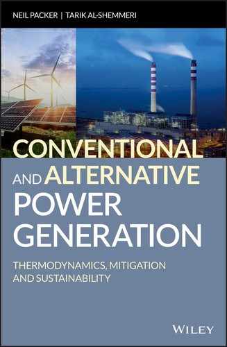
Consider the change in volume that occurs due to heating a unit mass of pure substance contained in a closed cylinder at constant pressure; take water (ice) as an example with an initial condition (temperature −10 °C; pressure 100 kN/m2). The change in specific volume corresponding to equilibrium states is illustrated by the successive piston displacements shown in Figure 1.3a and plotted on the temperature‐specific volume diagram of state shown in Figure 1.3b. It can be seen that there is very little increase in the specific volume of ice up to the melting point, B. At the melting point, there is a small but significant contraction to point B'. This is not typical of all pure substances; many substances show a small expansion at the melting point. Further heating in the liquid phase results in a small expansion as the temperature is increased to the vaporization point, C. At this point, the liquid is said to be in the saturated liquid condition. Further heating causes the progressive conversion of liquid into vapour, with a large increase in specific volume while the temperature remains constant. The process of conversion from liquid to vapour is completed at point C', which is known as the saturated vapour condition. Further heating gives rise to a gradual rise in temperature and specific volume in the vapour (or superheated steam) region, which is typified by point D.

Figure 1.3 (a) Formation of vapour (steam); (b) state diagram; (c) two‐phase definitions.
Line ABB'CC'D represents a typical constant pressure line on the temperature‐specific volume diagram of state in which the pressure lies above that at the triple point but well below the critical pressure. If the above process was carried out at a higher pressure, the large change in the specific volume at vaporization would be less pronounced. The abrupt change in specific volume disappears at the critical and higher pressures and a point of inflection occurs in the constant pressure line passing through the critical point.
At pressures above the critical value, there is no marked distinction in transition from the liquid to the vapour phase and it is usual to regard a substance as a gas at temperatures above the critical temperature.
The term dryness fraction (x) is only applicable for the wet region and, as described earlier, is defined as follows:

The total mass of the system = mass of vapour + mass of liquid, hence the system‐specific volume along the two‐phase line (Figure 1.3c) is:
Values of vf and vg and other properties for real substances are normally given in tables. Suffix ‘f’ refers to the liquid; suffix ‘g’ refers to the dry vapour.
At point C, x = 0 and thus v = vf whereas at point C', x = 1 and thus v = vg
Letting suffix ‘fg’ refer to the change of phase, i.e. vfg = vg – vf then
Either equation will give the same answer, however the second requires less data manipulation and hence is easier for manual calculation.
Similar expressions can be written for the specific enthalpy, specific internal energy and specific entropy of a substance:
1.5.1 Property Tables and Charts for Vapours
Tables giving data for saturated liquid and saturated vapour conditions, as well as the superheated values of v, u, h and s at a given pressure and over a range of temperatures are readily available. An example is shown in Table 1.1.
Table 1.1 Typical steam table.
| T | P = 2.00 MPa (212.42 °C) | ||
| v | h | s | |
| (°C) | m3/kg | kJ/kg | kJ/kg K |
| Sat. liquid | 0.00117 | 908.8 | 2.4474 |
| Sat. vapour | 0.09963 | 2799.5 | 6.3409 |
| 225 | 0.10377 | 2835.8 | 6.4147 |
| 250 | 0.11144 | 2902.5 | 6.5453 |
| 300 | 0.12547 | 3023.5 | 6.7664 |
| 350 | 0.13857 | 3137.0 | 6.9563 |
| 400 | 0.15120 | 3247.6 | 7.1271 |
| 500 | 0.17568 | 3467.6 | 7.4317 |
Note in the example used in Table 1.1that the saturation temperature, i.e. the liquid–vapour phase change temperature, is supplied in brackets after the pressure value.
Some property tables for water/steam are supplied in Appendix A.
Charts for steam that indicate h or T as ordinate against s (specific entropy) as abscissa are also available. An example is shown in Figure 1.4.

Figure 1.4 Temperature–entropy chart for water/steam.
Reproduced with permission from Moran, Shapiro, Boettner and Bailey (2012) Principles of Engineering Thermodynamics, 7th edition, John Wiley & Sons.
1.6 Ideal Gas Behaviour in Closed and Open Systems and Processes
An ideal gas is one which, if pure, will behave according to the ideal gas equation, also known as the equation of state. The equation of state expresses the relationship between pressure (P) and volume (V) as a function of the mass of gas (m), its specific gas constant (R) and the temperature (T) as follows:
The value of the gas constant depends on the gas molar mass, thus:
where Ro is the universal gas constant = 8.314 kJ/kmol K and M is the gas molar mass (kg/kmol).
For gas going through a process between conditions 1 and 2, the equation of state becomes:

An adiabatic reversible process is characterized by the following equation: ![]()
Therefore, between states 1 and 2, the following relationship can be deduced:
where n is the index describing the path of the process.
Combining Equations 1.5 and 1.6, the process can be described in terms of pressure and temperature thus:

Consider a working fluid undergoing a compression process. Equation 1.7 is used to determine the ideal temperature of the gas at the end of the compression process in terms of the initial temperature and the pressure ratio.
Since entropy is defined as a property that remains constant during an adiabatic reversible process, it follows that a temperature–entropy diagram would indicate such a process by a straight line perpendicular to the entropy axis if the process was purely isentropic (Figure 1.5). The friction in an irreversible process will cause the temperature of the gas to be higher than it would have been in a frictionless (reversible) process. Thus, the entropy increases during an irreversible process.

Figure 1.5 Concept of isentropic efficiency.
The isentropic process (1–2) is found from Equation 1.7 and the relation between the ideal temperature difference and that in the real process (1–2a) forms the isentropic efficiency for a compressor:

Thus, an irreversible compression process requires more work input than an ideal process due to the unwanted temperature rise.
When considering a working fluid undergoing an expansion, a reversible adiabatic or isentropic process (3–4) would, again, be illustrated by a vertical line when plotted on a T–s basis.
A renumbered Equation 1.7 is used to determine the ideal temperature of the gas at the end of the expansion process:

However, a real expansion (3–4a) would again suffer from irreversibilities, with its final condition having a higher temperature and an increased entropy relative to the isentropic case (see Figure 1.5). In this case, the isentropic efficiency for the expansion is given by:

1.7 First Law of Thermodynamics
The first law of thermodynamics is based on the conservation of energy within a system and, between any two state points, can be written as follows:
1.7.1 First Law of Thermodynamics Applied to Open Systems
The first law applied to an open thermodynamic system, i.e. one where mass may cross a thermodynamic boundary, is termed the Steady Flow Energy Equation (SFEE) and is expressed as:

Here, the LHS represents the heat flow and work transfers. On the RHS, the terms are, respectively: change in enthalpy, kinetic energy change and potential energy change between the start and end states (process).
Note that for an ideal gas, the change in enthalpy can be written as:
where Cp is the specific heat capacity at constant pressure (kJ/kg K) for the working fluid.
1.7.2 First Law of Thermodynamics Applied to Closed Systems
The first law applied to a closed thermodynamic system, i.e. one where mass does not cross a thermodynamic boundary, is termed the Non‐Flow Energy Equation (NFEE) and is expressed as:
where Q and W represent the heat and work during a process and the RHS represents the change in internal energy.
In general, the work done during a non‐flow process is represented by the following expression:

Note that for ideal gas, the change in internal energy can be written as:
where Cv is the specific heat capacity at constant volume (kJ/kg K) for the gas.
Some important points to note:
- For both SFEE and NFEE there is a sign convention for heat and work. It is common to regard heat leaving a thermodynamic system as heat loss (−ve) and heat entering the system as positive. The opposite is used with work; hence, work input to the system is negative whereas work exported is positive.
- In both forms, it is common to regard electrical energy and power as work or work transfer.
- The term adiabatic is used to denote zero heat or heat transfer, i.e.
 .
.
1.8 Worked Examples
All property values for the following questions can be found in Appendix A.
1.9 Tutorial Problems
Thermodynamic properties of water and steam are available in Appendix A.
- 1.1
Determine the specific enthalpy of steam (kJ/kg) at 20 MPa using steam tables for the following conditions:
- Dryness fraction x = 0.
- Dryness fraction x = 1.0.
- Dryness fraction x = 0.5.
- 1.2 Steam at 4 MPa, 400 °C expands at constant entropy until its pressure is 0.1 MPa. Determine, using steam tables, the dryness fraction of the steam at the end of the expansion process and the energy liberated per kilogram of steam under 100% isentropic conditions. [Answers: 0.902, 758 kJ/kg]
- 1.3 Repeat Problem 1.2 for when the expansion process is 80% isentropic. [Answers: 0.969, 606 kJ/kg]
- 1.4 An ideal gas occupies a volume of 0.5 m3 at 600 K and 100 kPa. The gas undergoes a constant pressure process until its temperature reaches 300 K. Determine:
- The final volume (m3).
- The work done during the process (kJ).
- 1.5 Self‐ignition would occur in an engine using a certain type of gasoline if the temperature due to compression reached 350 °C. Assume inlet conditions of 27 °C and 1 bar. Calculate the highest ratio of compression that may be used to avoid pre‐ignition (base your maximum temperature to 1 degree below that of self‐ignition) if the law of compression is:
 . [Answer: 11.36]
 - 1.6 A gas turbine operates between 9 bar and 1 bar. Helium is the working fluid, expanding adiabatically from an initial temperature of 1000 K and a mass flow of 0.1 kg/s. Determine the exit temperature (K) and the work done (kW) if changes in kinetic energy and potential energy across the turbine are negligible. For Helium, R = 2.08 kJ/kg K and Cp = 5.19 kJ/kg K. [Answers: 414 K, 304 kW]
- 1.7 A turbine manufacturer claims that his turbine will have an output of about 9 MW under the following conditions:
- Steam flow 10 kg/s at 6 MPa and 500 °C inlet condition.
- 100% isentropic expansion to a final pressure of 100 kPa.
- The heat transfer from the casing to the surroundings represents 1% of the overall change of enthalpy of the steam.
- The exit is 5 m above entry.
- The initial velocity of the steam is 100 m/s whereas the exit velocity is 10 m/s.
[Answer: yes]
- 1.8 A compressor takes in air at 1 bar and 20 °C and discharges at an average air velocity of 10 m/s and a pressure of 5 bar. Assuming that the compression occurs isentropically, calculate the specific work input to the compressor (kJ/kg). Assume that the air inlet velocity is very small. Take, for air, Cp = 1.005 kJ/kg K and n = 1.4.
[Answer: −172 kJ/kg]
- 1.9 A steam turbine receives 120 kg/minute of steam at 1 MPa, 350 °C and a velocity of 20 m/s. The exit condition from the turbine is 10 kPa, x = 1 and a velocity of 10 m/s. Neglect changes in potential energy and assume the process to be adiabatic. Estimate the power output from the turbine. [Answer: +1135 kW]
- 1.10 Find the change in value of specific enthalpy (kJ/kg) for water (steam) between an initial state where P = 100 kPa, saturated liquid, and a final state where P = 100 kPa and T = 350 °C. [Answer: 2758.85 kJ/kg]