

Figure 3.1Pentagon of Power
This book is not focused on machine design, but it would be silly to learn about automation without discussing some of the practical details of machinery since every piece of automated scenery requires a machine. There are a handful of prototypical machines (with countless variations) that every technician should be able to identify. Learning the catalog of common machines used in scenic automation will give you a starting point to solve specific problems in your productions. This chapter is a survey of common machinery with just enough mechanical information to understand the fundamental designs. The material presented here could be expanded into another book, and luckily that book already exists: Alan Hendrickson’s Mechanical Design for the Stage is a marvelous reference for greater depth on the subject.
A machine must have enough power to generate sufficient force to move an object at a desired acceleration. This simple statement requires a little bit of physics to meaningfully use it in practice. Let’s work our way through the three interrelated terms: power, force, and acceleration.
Acceleration
Acceleration is the change in velocity over time, or mathematically:
If a piece of a scenery needs to move from a standstill to 36 in/s in 3s, we calculate the acceleration:
or, more succinctly:
When speaking, you would say the scenery is accelerating at a rate of 12 inches per second per second. At that acceleration rate, every second that passes will increase the speed of the scenery by 12 in/s. After one second, the scenery will be traveling at a rate of 12 in/s. After two seconds, the scenery will be traveling at a rate of 24 in/s. After three seconds, the scenery will have met the desired speed of 36 in/s.

Figure 3.2Acceleration ramp
Force
Force exerted on an object causes a change in speed, and as we just defined, the change in speed is acceleration. An object will have many forces acting on it at the same time, all influencing the object’s acceleration. For instance, a chandelier hanging from a rope is being pulled down by gravity and held up by the tension of the rope. The net result of those forces is zero, so the chandelier hangs motionless.

Figure 3.3Chandelier resisting gravity
Force is calculated as mass times acceleration:
Force is measured in pounds (lbf) in the US, or newtons (metric) everywhere else. An increase in mass or acceleration will increase the force exerted. It follows that to move a heavier object at the same acceleration requires more force. The most common force we encounter is weight. Weight is the force of earth’s gravity exerted on an object, easily measured with a scale.
You’ll note that if acceleration is zero, the force is zero. An object in motion, with no other forces impeding its motion, requires no force to keep moving. In practice, there are always other forces acting on an object in motion. Friction slows down lateral movements as scenery is rolled across the floor and gravity pulls down as scenery is hoisted up, so these movements require force to move at a constant velocity to overcome those opposing forces that produce a negative acceleration.
Power
Force exerted over a distance is work. Pushing a roadbox up a long ramp takes more work than pushing the same box up a short ramp. Work over time is power. To do the same amount of work in less time requires more power. To push the same box up the ramp faster, you need someone to push with you. This is a critically important point in machinery: the amount of power required is determined by the speed and force. The same load can be moved with less power at a lower speed.

Figure 3.4Double the power to increase the speed of work
Power is measured in horsepower (HP) in the US, or watts (W) and kilowatts (kw) everywhere else. A horsepower is defined as the power used to move 550 pounds a distance of one foot in one second.

Figure 3.5A horsepower
To convert to watts:
To size up how much horsepower you need for a machine, you can plug in your basic requirements into this formula:
where:
P = power in horsepower
F = force in pounds
v = speed in feet per second
For example, if you need a lift to raise 1000 pounds at 18 in/sec, you can quickly see:
This calculation doesn’t include a design factor or account for the loss of power to mechanical inefficiency in the system that will turn some of the movement into heat, but it is useful to get a ballpark power budget. With this fast check, clearly a 1 HP machine is insufficient and a 10 HP machine is likely overkill.
Torque
Pounds and newtons are useful when quantifying linear force, but how can we measure the force of a rotating shaft or wheel? This is important since motors spin, turntables turn, and winches wind up rope, and we need to be able to calculate the forces involved. Torque is rotational force and is measured by the tangent linear force multiplied by the distance from the center of rotation.

Figure 3.6Torque
The units of torque are foot-pounds (ft•lb), inch-pounds (in•lb), inch-ounces (in•oz), and newton-meters (Nm). As you can see, the unit of torque is a linear dimension multiplied by a unit of force giving a hint as to how torque is calculated. The same force applied around a pivot will have greater torque as the lever grows longer. For instance, a 10 lb force exerted on a bolt with a 6 in wrench will produce 60 in•lb of torque. When using a 10 in wrench, the same 10 lb force will produce 100 in•lb of torque. If you’ve ever struggled with a stuck bolt, you know that a longer wrench produces more torque.
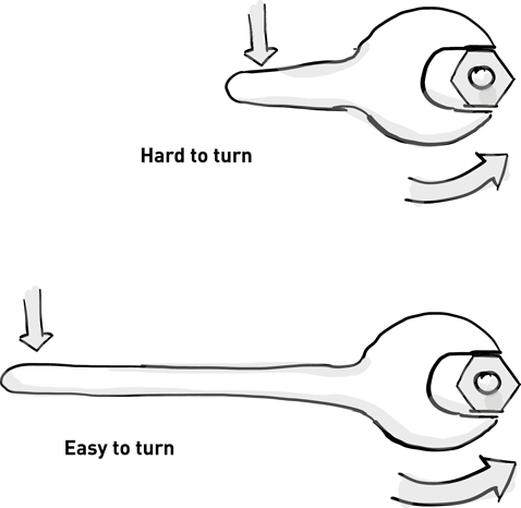
Figure 3.7Small wrench vs. big wrench
A wrench takes a linear force and converts it to torque when turning a bolt. A rotary motor produces torque around its output shaft, which can then be converted into a linear force through a mechanism (such as a wheel, drum, cam, or link bar).

Figure 3.8Motor torque producing linear force through torque arm
The force exerted by the motor wanes as the load is moved further from the center of its shaft. If a motor produces 100 in•lb of torque, it exerts 100 lb of force 1 in from the center of the shaft, but the force decreases to 20 lb at 5 in from the center of the shaft.

Figure 3.9Small drum vs. big drum
To calculate the torque of motor:
A 1 HP motor, with a nameplate speed of 1750 RPM, produces in•lb of torque as you can see here:
These basic calculations of force, torque, and power are enough to explore the machinery in this chapter.
All machines share some common components that are used as building blocks in mechanical design.
Speed Reducer
Looking at the torque output of a 1 HP motor, two things are apparent. First, the output speed of it is very fast: 1750 revolutions per minute is roughly 30 revolutions per second. If a 6 in wheel was attached to the shaft, the motor would cruise along at a brisk 45 feet per second. Second, the force produced is paltry: 36 in•lb of torque would exert only 12 lb of force at the edge of the 6 in wheel.

Figure 3.10Friction wheel machine without speed reducer
To reduce speed and boost torque, we need to lower the output speed mechanically. Commonly, a motor is connected to a geared speed reducer. The speed reducer is specified with a ratio between the input and output shafts. A 20:1 speed reducer will reduce the speed by a factor of 20 and increase torque by the same amount. In our example, if the 6 in wheel is attached to the output shaft of such a speed reducer the speed drops to a reasonable 2.25 feet per second and the linear force jumps to 240 lb.

Figure 3.11Friction wheel machine with speed reducer
Speed reducers are built with different gear configurations that have either parallel or right-angle output shafts with differing efficiency ratings. A low-efficiency speed reducer will lose more mechanical energy input as heat.

Figure 3.12Parallel speed reducer

Figure 3.13Right-angle speed reducer
A timing belt between two pulleys of differing diameters can also be used to reduce the speed of a motor and increase torque. Unlike the high reduction ratios of a geared speed reducer, the maximum reduction ratio between timing belt pulleys is typically limited to 7:1.

Figure 3.14Timing belt pulley speed reduction
Roller chain and sprockets can also be used for speed reduction, but normally should be reserved for low-speed, high-load reduction designs. For instance, roller chain can be used as an additional reduction after a geared speed reducer. In such a case, the ratio of the chain reduction is multiplied by that of the geared speed reducer to calculate the overall reduction ratio. If a 2:1 chain reduction is placed after a 20:1 geared reduction, the total reduction is 40:1.

Figure 3.15Chain reduction and gear reducer
Roller chain comes in different sizes to match the load and speed requirements of the machine. In the US, ANSI chain sizes commonly used are #25, #35, #40, #50, #60, #80, and #100. The pitch of the chain, which is the distance between pins in the chain, increases with the trade size. Larger chains have higher load capacities, though multiple strands of a lesser trade size can also be used to achieve higher load capacities. To select the correct size chain, consult the rating tables of the roller chain manufacturer such as Martin or Tsubaki.

Figure 3.16Roller chain pitch
| ANSI size | Pitch |
| 25 | ¼ in |
| 35 | 3/8 in |
| 40 | ½ in |
| 50 | 5/8 in |
| 60 | ¾ in |
| 80 | 1 in |
| 100 | 1 ¼ in |
Shafts
Steel shafts are used to transmit torque from a motor to the primary mechanism in a machine. As the motor spins so should the attached sprocket, wheel, gear, drum, or other linkage. To lock these components onto a round shaft, the shaft will have a rectangular keyway cut into the metal. A mating component will have the same keyway cut into its bore. A square key, made of steel, is inserted into the void created by the two keyways and transmits the rotary motion from the shaft to the component.

Figure 3.17Shaft, sprocket, and key
The keyway size is determined by the diameter of the shaft.
| Minimum shaft diameter | Maximum shaft diameter | Keyway width |
| 3/8 in | 7/16 in | 3/32 in |
| ½ in | 9/16 in | 1/8 in |
| 5/8 in | 7/8 in | 3/16 in |
| 15/16 in | 1 ¼ in | ¼ in |
| 1 5/16 in | 1 3/8 in | 5/16 in |
| 1 7/16 in | 1 ¾ in | 3/8 in |
| 1 13/16 in | 2 ¼ in | ½ in |
| 2 5/16 in | 2 ½ in | 5/8 in |
Shaft keyways can be cut into unhardened shafts with a milling machine, or shafts can be purchased with keyways pre-cut. Keyways can be cut into the bore of a mating component with a broach and a press, or the mating component can be purchased with a finished bore and keyway.
Bearings
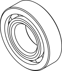
Bearings are used to transfer load from the moving parts of a machine to its stationary frame. Radial bearings are used to support a load perpendicular to the axis of rotation.

Figure 3.18Radial bearings supporting a spinning shaft
Thrust bearings are used to support a load parallel to the axis of rotation.

Figure 3.19Thrust bearing supporting a turntable
Linear bearings are used to support a sliding load.

Figure 3.20Linear bearing on a rail
Bearings are rated by their load capacity and speed. Different bearing materials and constructions are used to meet the demand of the mechanism. Here are some common bearing options:


Mounted bearings are purchased in a manufactured housing with convenient bolt holes that allow for easy installation into a machine frame. The mounting also allows for slight misalignment between the shaft and the mounting surface. The most common mounted bearings are pillow blocks and flanged blocks.

Figure 3.27Pillow block and flanged block

Figure 3.28Flanged block allows some misalignment
Bearings can be purchased unmounted and then pressed into a custom housing. This requires precise machining and a mechanical press. If a rigid mount is desired, or a slimmer profile needed, a custom bearing housing may be a good choice.

Figure 3.29Rigid bearing mount
Couplings
A shaft coupling transmits motion from one shaft to another. The coupling can also compensate for misalignment between shafts. Shafts may be installed with angular misalignment or parallel misalignment and compensating for each misalignment requires different couplings.

Figure 3.30Angular vs. parallel misalignment


Brakes
Spring-set brakes are used to hold a motor or machine stationary in between movements. These brakes hold the load when power is removed and release when energized. Because the brakes engage when power fails, they are called “failsafe” brakes. Brakes that mount on a shaft are rated by their holding torque. Some brakes are built to be mounted on a motor before the speed reducer. In that mounting arrangement, the holding torque of the brake is multiplied by the speed reducer just as the motor’s torque is increased. In contrast, brakes with much larger holding capacity can be mounted on output side of the speed reducer. These brakes do not rely on the speed reducer for their braking action.

Figure 3.36SpotlineTM hoist with motor brake and load brake
Source: Courtesy of Creative Conners, Inc.
Brakes are specified by torque rating and operating voltage. The operating voltage is important when designing the controls to switch the brake on and off, as we’ll see in later chapters.
Winches are the workhorses of theatre automation. Mechanically, a winch is a device that converts the rotary motion of a motor into linear motion. In simple terms, a winch is a machine designed for pulling. These are flexible machines, easily pulling a wagon across stage, pulling a curtain, pulling a line set, or even pulling on the edge of a turntable. Typical maximum speeds for a winch range from 18 in/sec to 48 in/sec, though slower or faster speeds may be required. Force requirements have a broad range from less than 50 lb to thousands of pounds, but a respectable deck winch will usually be in the range between 250 lb to 1000 lb of maximum pull force.
The anatomy of a basic deck winch includes a drum, motor, speed reducer, spring-set brake, encoder, limit switches, and cable tensioning.

Figure 3.37Deck winch anatomy
Source: Courtesy of Creative Conners, Inc.
Let’s step through each of the major components while considering the design for a new deck winch. For this example, let’s presume the winch being designed should be capable of producing 500 lb of pull at speeds up to 36 in/sec with 90 ft of cable capacity.
How much scenery could such a winch pull? The unsatisfying answer is, “It depends…” The construction of the scenery and the quality of the casters play an important role in how much force it takes to push a given weight on wheels. In practice, I’ve found that a conservative estimate is a force 1/10 of the scenery’s weight is required to move scenery on casters. If possible, it’s great to have the scenery constructed and measure the force required, but that is a rare luxury. I heard a tale that Peter Feller, of Feller Precision fame, would grab a bathroom scale, mount it to the scenery needing a winch, and push on the scale. As he pushed, he could watch the numbers on the scale climb with his increasing force. Once the scenery started to move, he noted the scale’s number and sized the winch to suit. Though I’ve never used a bathroom scale so ingeniously, I have often used a torque wrench to measure how much force is required to spin a motorless winch with a scenic load attached. Both techniques serve as a reminder to be an unashamed pragmatist when determining real load requirements.
Drum
A winched deck track uses a closed loop of cable to pull scenery both onstage and offstage. The winch has a drum to wind the cable back and forth. The ends of the cable are terminated in the drum to prevent any slip that would lead to poor positioning when the winch is eventually controlled by the automation system. As the drum spins, the cable unwinds from one side of the drum, and winds onto the other. This arrangement is often called “push-pull” or “roll-on, roll-off.”

Figure 3.38Deck winch rigging
Source: Courtesy of Creative Conners, Inc.
To keep the cable orderly as it winds around the drum, the drum has a concave, helical groove cut into the surface. As the drum spins, the cable threads on and off the groove of the drum. The drum is one of the most expensive components in the winch and typically custom-machined. Since it is a custom component, the diameter of the drum is often dictated by the tooling available in your shop or your preferred machine shop. In a conventional winch, the drum is made at the largest possible diameter to minimize the length required to hold the required amount of cable. By increasing the diameter and minimizing the length, the wire rope will not traverse as far across the drum and thus reduce the fleet angle of the cable at the extreme ends of travel.

Figure 3.39Large drum fleet angle vs. small drum fleet angle
Let’s assume that the maximum diameter drum we can manufacture is 10 in. To calculate the length of the drum, we must consider the size of the wire rope we intend to use and the capacity required. I prefer to use ¼-in wire rope on deck tracks. It is overkill in most cases for the load rating, but it is nice and stiff which leads to smoother motion since the rope doesn’t stretch as much as a thinner one. For proper spacing, a pitch of 3 TPI (threads per inch) is used.

Figure 3.403TPI drum pitch
The 10 in drum has a circumference of:
Looking back at the original specification, we wanted to have 90 ft, or 1080 in, of cable capacity on the drum. If each wrap of cable on the drum is ~31 in, then we can calculate the number of wraps needed:
Since the drum will be cut with 3 TPI, the length of the drum can be calculated:
However, we should add a little bit extra to the length of the drum to leave space for safety wraps at either end of the drum. At full travel in either direction, the drum should still have 3 wraps of cable left on the drum, so the drum needs to hold 41 wraps in total (35 + 3 + 3). With a pitch of 3 TPI, that means that we should add 2 in onto the length of the drum for a total length of 14 in.

Figure 3.41Drum length
Motor, Brake, and Speed Reducer
With the drum size determined, the next step is to figure out the motor and speed reducer that will spin the drum. From the initial design specification, this winch should produce 500 lb of force at a speed of 3 ft per second. Using the definition of horsepower, we can quickly determine the horsepower required for this winch:
Next, we need to figure out the maximum speed of the drum in RPM to meet the design goal of 36 in/sec.
For the ultimate in convenience, we can buy the motor and speed reducer in a pre-assembled package from a gearmotor manufacturer like SEW-Eurodrive, NORD, KEB, or many others. If we use the excellent PT Pilot tool from SEW-Eurodrive (www.seweurodrive.com/s_ptpilot/), it’s easy to view possible combinations that satisfy the calculated horsepower and output speed.

Figure 3.42PT Pilot SEW motor spec

Figure 3.43PT Pilot SEW selection chart
The KA47 with a 25.91:1 reduction looks like a good choice. The output torque rating is 2730 in•lb. Will that be enough? Let’s check the torque required to produce 500 lb of force with a 10 in drum.

Figure 3.4410” drum, 5” radius, and 500 lb force
Yes, the torque output from the motor is higher than the torque required to generate 500 lb of force from the drum. It’s worth mentioning that we are running close to maximum capacity (92%) of the gearmotor. If the 500 lb specification is an intermittent load, then this is probably fine for a deck winch. However, if that load is going to be consistently demanded of the machine, it would be wise to increase the horsepower to attain 25–30% of unused capacity in the power output. This will extend the life of the machine and give a little headroom for unexpected demands on stage.
SEW-Eurodrive can also supply a pre-mounted brake on the gearmotor. The standard option is a 248 in•lb spring-set brake which should fit the bill nicely.

Figure 3.45SEW brake
Encoder and Limit Switches
Since this winch is destined to be controlled by an automation system, it requires feedback sensors for accurate positioning. An encoder is used to sense how far and how fast the motor is moving. We’ll dig into the details in Chapter 6, but for now we just need to know that this sensor has to be mounted on the machine. There are two reasonable options: mount the encoder on the motor, or mount the encoder on the drum shaft.

Figure 3.46Encoder placement: motor or drum
If the encoder is mounted on the motor, it will sense the movement of the motor shaft which is spinning ~25x faster than the drum shaft since the drum is mounted to the output shaft of the speed reducer. This position will give finer resolution and typically better control. SEW-Eurodrive can pre-mount the encoder on the gearmotor, which eliminates any fabrication steps.

Figure 3.47SEW encoder selection
In addition to an encoder, limit switches should be mounted in the winch to protect against running too far in either direction. A rotary limit switch has a series of cams and snap switches packaged in a convenient housing. The input shaft will rotate the cams. The lobe on each cam can be positioned to strike the corresponding snap switch at a certain point in the rotation. The entire travel of the cable on the winch drum can be described by a single rotation of the cam. One cam is set to strike a switch at the furthest reverse point, another is set to strike a switch at the furthest forward point.

Figure 3.48Rotary limit switch
The switch is specified with a reduction ratio. The cams shouldn’t rotate more than once for the entire travel of the cable along the drum. Since we have 41 wraps of cable on the drum, the rotary limit switch must have at least a 41:1 reduction. A standard 50:1 rotary limit switch from one of the popular manufacturers such as Ravasi or Stromag would suffice. The switch can be driven from the drum shaft with a roller chain or timing belt.

Figure 3.49Rotary limit switch driven by chain
Source: Courtesy of Creative Conners, Inc.
Tensioner
It is important to keep the rope tightly wound on the drum, so some sort of rope tensioning device needs to be included in the system, whether part of the winch design or an external device. In this example, we will be moving a wagon back and forth across stage. Our winch is stage right and our wagon starts from stage left. One rope is attached to the wagon and goes directly to the winch – this is the rope that will pull the wagon stage right. The other rope is attached to the other end of the wagon and first goes around a floor mounted pulley stage left before heading back to the winch stage right. This is the rope that will pull the wagon stage left. In order to tension both ropes, we need only move the floor-mounted pulley further stage left. Since the wagon is part of the rope loop, moving the pulley one inch stage left will take out two inches of slack from the rope – one inch from each side. This is a very effective means of tensioning the rope and the tensioning device is fairly simple to build.

Figure 3.50Tensioner turnaround
Source: Courtesy of Creative Conners, Inc.
Another method is to build the tensioning device into the winch itself. Most theatrical winch designs include a pair of pulleys to direct the ropes to the drum, since the drum is usually above the tracks in which the ropes move. Often, these pulleys float on the same shaft, moving side to side as they follow the ropes winding across the drum. Moving this shaft away from the drum or away from the track – or both – will remove slack from the loop and increase tension. If the arrangement of the shaft and pulleys is such that they move away from the track and the drum simultaneously, then one inch of movement will take four inches of slack from the rope. This is a very common tensioning scheme, but requires a means of moving both ends of the pulley shaft.

Figure 3.51Deck winch built-in tensioner
Source: Courtesy of Creative Conners, Inc.
This floating “feed” pulley scheme is a very common design in theatrical drum winches; not only does it permit tensioning, it also helps to prevent the rope from piling on by following the rope as it moves in its groove. One might be tempted to use pulleys with high-quality ball bearings for this application, but that is not a good idea. Plain bronze sleeve bearings work best, because of the sliding action between the shaft and the bearing surface. With a ball-bearing pulley, the inner race does not turn, so there is no sliding action between the bearing and the shaft and the pulley will tend to stick. The same is true of the shaft; the shaft should not rotate either.
Zero Fleet Winches
The cable on a conventional winch walks back and forth across the drum as the drum spins. This introduces a fleet angle and requires a healthy distance between the winch and the first set of mule pulleys that direct the cable into the winch track to reduce cable wear and noise.

Figure 3.52Deck winch fleet angle
Source: Courtesy of Creative Conners, Inc.
With a “zero-fleet” winch, the rope enters and exits the winch via a pair of stationary feed pulleys. Since the rope no longer moves side to side in this design, there is no change in the fleet angle of the rope with respect to whatever the winch is pulling – hence the name. This greatly simplifies placing the winch on stage. The drawback to this design is added complexity and cost because a level-winding mechanism must be included to keep the rope from piling on the drum. There are two main level-winding designs: moving pulleys and moving drums.
In the first, a pair of pulleys are moved along the drum to guide the ropes into the groove. The mechanism to move the pulleys is usually an acme screw with a thread pitch that matches the pitch of the groove in the drum. These pulleys, in turn, send the ropes through a pair of mule pulleys (which can be used for tensioning) and then to the stationary feed pulleys.

Figure 3.53Traveling pulley zero fleet
The second zero fleet option is to move the drum back and forth past the stationary feed pulleys. In this configuration, the motor, gearbox and drum are mounted on a sled which is driven, like the pulley system above, by a screw with the same pitch as the drum. This requires a larger winch frame since the winch will be at least twice the length of the drum.

Figure 3.54Traveling drum zero fleet
Source: Courtesy of Creative Conners, Inc.
Deck Dogs and Knives
To connect scenery to the winch cable, a piece of hardware called a Dog is employed. The dog is constructed out of steel or hard plastic. It lives beneath the show floor and travels inside a winch track built into the subfloor. The winch cable runs through a hole in the dog and the dog is affixed to the cable either with set screws or nicopress stops. Set screws allow for easy adjustment after installation, but can slip under heavy load. Nicopress stops are permanent and cannot be adjusted after installation, but don’t slip under heavy load. My preference is to use set screws because I would rather have the option to adjust the location of the dog on the winch cable. Additionally, allowing the dog to slip under heavy load can be a feature when scenery crashes together accidentally.

Figure 3.55Dog fastened to cable
Source: Courtesy of Creative Conners, Inc.
The dog has a slot in its top face to accept a ¼ in x 2 in steel knife. When scenery is rolled over the winch track, the knife is slid through a slot in the scenery and into the dog. With the knife engaged, the scenery will move as the dog moves. The scenery will have a second knife that rides in the winch track to keep the other end of the scenery wagon in-line with the winch track.

Figure 3.56Knife connecting scenery to dog
Source: Courtesy of Creative Conners, Inc.
Turntables are a popular automated effect on stage. A motor spins a circular section of floor to provide an endless treadmill for performers, or flip the scenery around revealing a new setting, or to show off the latest model car during a product launch. A rotating stage is both mechanically simple and visually exciting, which makes it great value. Maximum speeds of 1 RPM to 3 RPM are common, though faster or slower speeds may be required for some performances. Horsepower requirements vary greatly given the wide range of turntable diameters, loads, and deck construction methods. However, most vanilla-flavored turntable demands land between 2 HP and 5 HP for decks up to 24 ft in diameter, and between 5 HP and 10 HP for decks up to 40 ft in diameter.

Figure 3.57Turntable with surround deck
Despite the conceptual simplicity, turntables have several key components that need to be considered to insure trouble-free operation.
Deck Construction
Turntables are usually larger than a single platform and must be built to break apart into manageable sections. These sections can be shaped either as pie wedges or as rectangles with curved edges at the perimeter.

Figure 3.58Turntable pie wedges vs. rectangles
Pie wedges hold the advantage that all the pieces are the same and can be built from a common jig to speed fabrication. However, the pie wedge shape is not as conducive to storage and transport. The odd shape requires custom storage carts and can eat up valuable storage space on a truck or in a warehouse.
Splitting a turntable into rectangular decks leverages existing stock for the pieces that don’t sit on the perimeter. Perimeter pieces require curved edges, therefore each perimeter piece will be custom fabricated.
Regardless of deck shape, the pieces can either be framed as typical platforms or assembled out of frameless layers of plywood with overlapping seams. Framed decks are more rigid and require fewer casters, but the individual decks tend to be heavier. Frameless decks can be assembled with fewer people since no section is more than a single sheet of plywood, but require a lot of casters to reduce flex in the floor surface. For high loads, several sheets of plywood are required, which greatly increases the overall weight of the turntable, even if the individual pieces are lighter.

Figure 3.59Turntable framed vs. frameless
The wheels upon which the turntable spins can either have their mounting brackets bolted to the turntable and roll along the floor, or fastened to the floor and roll along the underside of the turntable. If the casters are attached to the turntable, this is called “wheels-down,” while “wheels-up” implies that the casters are attached to the floor and the wheel is pointing skyward like the feet of capsized turtle.

Figure 3.60Turntable wheels up vs. wheels down
Wheels-up is preferred in most cases; wheels make noise when they bump over debris on the floor. If the wheels are pointing up, any debris will fall to the floor without interfering with the wheels’ movement. Another source of noise is wheels crossing gaps or unlevel seams in the stage floor. It is easier to make a tight, level turntable deck than to fix up the stage floor to be perfectly flat.
The wheels can either be fastened directly to the floor or onto a subframe. The subframe adds height to the turntable profile and additional fabrication, but makes setup and strike quicker. It also makes leveling the turntable easier since the frame can be leveled and shimmed as a unit rather than shimming each individual caster.

Figure 3.61Spider vs. individual casters
Whether mounted directly to the floor or onto a subframe, keeping the casters fixed relative to the stage allows cables to be run along the stage floor without them being trampled by the turntable. This is particularly important if electric cables are to be run up to lighting effects on the turntable. If the turntable only makes a single revolution (or a little more), then cables can be passed up through a hollow center in the turntable. If endless movement is required, then an electrical device called a slip-ring is used to transfer electricity through the turntable.
With all the advantages of wheels-up, what monster would ever choose to build a turntable wheels-down? Well, there are some advantages of wheels-down. First, wheels-down means simpler installation. If all the casters are attached to the turntable deck pieces, then it isn’t necessary to install all the wheels on the stage first and then install the turntable decks; instead, just plop the decks on the stage and it’s finished. Second, the height of the turntable is lower with wheels-down if building framed decks. The wheels can tuck up into the frame of the deck, which lowers the overall height by the thickness of the frame when compared to a wheels-up design.

Figure 3.62Wheels down tucked into frame
Pivot
The success of a turntable revolves around the center pivot point. The pivot’s job is to join the turntable deck to the stage floor and allow the turntable deck to spin around a fixed point on the stage. It should have a mounting plate to anchor the bottom of the pivot to the stage floor and another mounting plate to attach the turntable deck. The pivot must be stout enough to keep the turntable from sliding across the stage, but allow it to spin freely.

Figure 3.63Turntable pivot
There are a lot of options for making a turntable pivot; space requirements, budget, and fabrication ability will determine the best choice.
A chunk of steel shaft with a close-fitting sleeve is a cheap pivot with reasonable performance. Mounting plates can be welded (or bolted) to the shaft and sleeve to make the connection between the stage floor and turntable deck. A layer of grease between the sleeve and shaft is crucial for low-friction rotation; don’t be shy with the grease.

Figure 3.64Shaft and sleeve pivot
The two halves of this pivot aren’t fastened together. This makes it easy to install the pivot base on the stage, the upper pivot onto the underside of the turntable deck, and then drop the turntable onto the pivot base. As the turntable spins, it can float vertically to compensate for any inconsistency in the flatness of the stage floor.

Figure 3.65Turntable installation with shaft and sleeve
Mounted bearings provide less resistance and will have a longer life than the pipe and sleeve pivot. However, flanged blocks are made to be self-aligning and therefore will not hold the shaft rigidly vertical which allows the turntable to slide around the stage.

Figure 3.66Single flange block is insufficient for a turntable pivot
To fix the shaft vertically, a pair of flanged blocks should be used. The bearings are rigidly mounted to a frame to hold them in a fixed orientation to each other.

Figure 3.67Double flange block is rigid for a turntable pivot
A sleeve is fastened to the underside of the turntable deck. A machine key or pin can be used to hold the sleeve onto the pivot shaft. If a machine key is used, a rigid shaft coupler with keyway can be purchased to avoid broaching the keyway in your shop.

Figure 3.68Sleeve fastened to underside of turntable
A slewing ring is a bearing purpose-built for turntables. Often used in industrial rotary positioning tables, cranes, and boom lifts, these bearings can handle large radial and axial loads.

Figure 3.69Slewing ring handles radial and axial force
Both the lower and upper bearing races have mounting holes for easy fastening between the stage floor and turntable deck.

Figure 3.70Slewing ring easily attaches to top and bottom
The open center allows for cables and hoses to pass through the center of the turntable. The upper or lower race can be purchased with either a gear tooth or timing belt pulley profile to facilitate a center-drive machine, or attaching positioning sensors.

Figure 3.71Slewing ring with gear tooth
The downside to slewing rings is the expense and lead time. Heavy-duty models can be several thousand dollars and take months to get. However, distributors may have some surplus inventory on the shelf that can be had at a discount. Alternatively, Igus also makes a series of medium-duty bearings that are made from aluminum with plastic bearing material, which is substantially cheaper than steel ball-bearing or roller-bearing models from manufacturers such as Kaydon. These medium-duty bearings are also typically either stock or available within a few weeks of order.
Drive Mechanism
A motor is used to spin the turntable. The motor can spin the turntable either from the center, or from a point around its edge. Each placement has compromises that should be considered.
Perhaps the conceptually simplest mechanism for spinning a turntable is to rotate the center pivot. The machine and center pivot can be built as a single module, which is quick to install. However, the torque required to spin a turntable from the center grows huge as the diameter of the turntable increases. This requires either a massive gear reduction in the speed reducer, or typically a second transmission between the output of the speed reducer and the center pivot. This second transmission could be a roller chain, timing belt, or a spur gear and slewing ring.

Figure 3.72Large sprocket with slewing ring
The advantages of center drive are the simplicity of installation and the elimination of any slip between the motor rotation and the turntable movement. The disadvantages are the space required to hide the mechanism below the turntable and the massive torque generated around the center pivot. This requires more engineering in the turntable deck and the connection to the stage to transmit the torque from the center to the edge of the deck without twisting either the turntable or stage into a pretzel. This is a distinct concern during starting and stopping. As you will recall from page 33, force grows as the acceleration increases. During an Emergency Stop, the deceleration (or negative acceleration) is severe and can generate huge force in a large, loaded turntable. That force requires serious analysis when designing a center-drive turntable machine.

Figure 3.73Center-drive turntable produces large concentrated force
To reduce the torque demands on the turntable machine, the mechanism can be placed away from the center to spin the outer edge of the turntable.

Figure 3.74Turntable rim drive
In this arrangement, the turntable deck becomes part of the speed reducer. If a turntable is 24 ft in diameter and a 1 ft wheel is placed on the machine, then the speed reduction between wheel and turntable is 24:1. Therefore, it will take 24 revolutions of the wheel to spin the turntable one revolution, and the torque exerted around the center pivot is 24 x greater than the torque produced by the drive wheel.

Figure 3.75Rim drive uses the turntable as part of the gear reduction
The motion between the machine and the turntable can be transmitted in several ways. A rubber wheel is the easiest and cheapest method, using friction to spin the turntable. However, a rubber wheel doesn’t have a positive engagement and can slip. A tensioning mechanism is required to keep pressure on the rim and minimize slip. The inherent slip can act as a clutch and allow the turntable to slide through the wheel under excessive force, but it can also cause positioning inaccuracy.

Figure 3.76RevolverTM v2 is a rim-drive machine with a friction wheel
Source: Courtesy of Creative Conners, Inc.
A roller chain can be wrapped around the entire circumference of the turntable deck. The roller chain can use friction to grip the turntable, or a sprocket tooth can be cut into the edge of the rim. Cutting a giant sprocket profile eliminates any possibility to slip, but requires some precise design and cutting with CNC tooling to implement.

Figure 3.77Chain wrap as friction drive or positive engagement in cut teeth
A wire rope can be wrapped around the turntable a few times and driven from a winch. If continuous rotation is required, the cable can be built as a closed loop, called a grommet, and driven with a grommet winch that uses a flat drum without any grooves. This has all the same slipping issues as the other friction drives. Additionally, it requires splicing a custom loop of wire rope to a specific length.

Figure 3.78Grommet winch
If a limited number of rotations is acceptable, the cable wrapping around the turntable can be terminated in a standard deck winch.

Figure 3.79Deck winch running a turntable
I am not a fan of driving a turntable with a cable wrap. Wire rope tends to slip more than any other of the friction drives, tends to be loud, and stretches considerably, thus requiring a lot of adjustment during setup and rehearsal. However, this method allows for a low-profile turntable. Very little vertical space is required at the turntable to wrap the cable around the edge of the turntable. The winch driving the cable can be hidden offstage rather than requiring the machine to be buried under the stage deck like the rest of these mechanisms.

Figure 3.80Cable-drive turntable can be a low-profile solution
Wire-rope hoists are cousins of the deck winch we discussed earlier in this chapter. They share most of the components and function similarly, but are purpose-built for vertical lifting applications instead of lateral pulling. Because of the inherent increased risk, hoists are engineered and built with more rigor than deck winches. The ANSI standard E1.6-2012 covers the requirements for hoists that should be followed by anyone building or maintaining these machines, but there are a handful of distinguishing features that we should discuss here.
To prevent a hoist from dropping its load if a brake malfunctions, all hoists are required to have two spring-set brakes for redundancy. Though not specifically required, most hoists are made with one brake before the speed reducer and a second after the speed reducer to protect against a failure inside the speed reducer. The brake on the output side of the speed reducer must have a much higher holding rating since it can’t leverage the mechanical advantage of the speed reducer. It must be strong enough to hold the load directly and is thus physically much larger. Because of its increased size, it releases much more slowly than the motor-side brake. This difference in timing needs to be considered when designing a control circuit to release the brakes.

Figure 3.81SpotlineTM hoist with dual brakes
Source: Courtesy of Creative Conners, Inc.
Hoists should be equipped with an overspeed detection mechanism, either mechanical or electronic, to stop the machine if it loses control of the load and descends in freefall.
On a deck winch, a pinch roller is often installed on the drum to keep the cable neatly wrapped on the drum. This pinch roller prevents a cabling mess if tension is lost on the deck track. The stakes are significantly higher on a hoist if the cable pops out of the drum. The rope suspending the load is designed to take the force exerted by the drum, but if the cable comes out of the drum and winds around the drive shaft the force is magnified because the same output torque from the motor is being exerted across a smaller radius. This excessive force may break the rope and drop the load. To avoid this hazard, a cross-groove detector should be installed to turn off the hoist if the cable comes out of the drum grooves. The cross-groove detector is sometimes incorporated into the pinch roller, or it may be a separate device.

Figure 3.82Force changes dramatically when wire rope falls off drum
Since the hoist is used for lifting, gravity should keep the rope taut and thus the machine won’t need a tensioning mechanism like a deck winch. Further, if the rope does go slack, that indicates that the load is held up by something other than the rope. A slack line can present a serious hazard. For example, if a batten is lowered and hangs up on a set piece, without detection of the problem the hoist will continue to unspool the rope. If the batten comes free, it will fall until the rope catches it. That shock load may break the rope or other components causing the batten to drop. To prevent such hazards, the hoist should be equipped with slack-line detection to stop motion if the rope slacks.
Lastly, hoists should be equipped with overload sensors to enforce a safe working load by limiting the amount of weight they can pick up.
The other vertical lifting machine in our catalog is the stage lift. Hoists pull from above, lifts push from below to raise performers and scenery. Lifts inherit similar safety concerns from hoists, but often add a few more hazards to the list of concerns when used as transport from the trap room to the stage. The underside of the stage is a severe pinch point that can sever anything poking out beyond the lift platform. Additional safety guards are used to prevent gruesome accidents (see Chapter 10).

Figure 3.83Pinch points from lift
When used as part of the stage floor, an excessive load can be rolled onto the lift platform. The lift, due to its redundant safety brakes, can hold the load but may not be able to safely lower in a controlled fashion. The lift should be equipped with load sensors that lock out motion if an excessive load is placed on the lift.

Figure 3.84Excessive load on lift in the up position
There are numerous different mechanisms used for lifting, but the two most popular solutions that can be installed and struck for a production are scissor lifts and four-post lifts.
Scissor Lifts
Scissor lifts are a handy, self-contained solution. The lifting mechanism and primary guidance are built into the machine. Collapsed, most lifts are less than 24 in tall, making them easy to store. A variety of lifting heights is available, which must be specified at the time of purchase, since the height can’t be easily extended after manufacturing. Load capacity must also be determined prior to ordering. Scissor lifts are typically hydraulically powered, though there are some electric variations.

Figure 3.85Scissor lift expanded and collapsed
Scissor lifts are heavy and take some serious material handling equipment to place down in a trap room. Because of the nature of the scissor mechanism, the speed of the platform raising varies greatly with a constant oil flow. At the low position, a little cylinder movement creates a large vertical movement. When the platform nears its full extension, it takes a large cylinder movement to raise the lift platform a small amount. This can make controlling the lift platform speed a little tricky.

Figure 3.86Scissor fast when collapsed, slow when extended
Scissor lifts are very stiff across the crossing members, but the platform is quite wiggly perpendicular to the crossing members. This instability often requires some external guidance surrounding the lifting platform.

Figure 3.87Scissor stiff left to right, wiggly front to back
Four-Post Lift
A platform, guided at the corners with vertical posts, can be hoisted to create lift. In this arrangement, cables are run from the corners of the platform, up the respective post, and over to the hoist through a series of pulleys. These lifts can be much lighter than a scissor lift and more easily adjusted to different sizes by altering the platform or columns.

Figure 3.88Four-post lift
A four-post lift requires more installation time to set the columns and install the rigging than a scissor lift. The platform is also less stable than a scissor lift. Placing a load in one corner can tip the platform up in the opposite corner. To stabilize the platform, a Mayline made from wire rope can be installed.

Figure 3.89Mayline
In venues that lack a proper flyhouse, a roll drop machine can be used to unroll drops into view and then roll them back up for storage like a big roller shade. Typically, these machines are mechanically dead simple: a motor spins a big tube with a drop attached.

Figure 3.90Roll drop machine
The devil is in the detail of construction to make a good structure to wind up the drop evenly. Because these machines often span much of the stage, the tube is quite long. If the tube is not rigid enough, it will deflect significantly in the center of the span. When it spools up the drop, the fabric will sag and bunch and look terrible.

Figure 3.91Roll drop tube flexes over long distances
To combat this, a large tube with rigid connections at any seams must be constructed. Often these tubes are made from aluminum, though Gerriets International makes a fancy roll tube out of carbon fiber which is lovely.
Even the best roll tube will deflect some in the center of the span. To make the soft goods look their best when in full view, it often helps to snap a horizontal line on the roll tube and affix the top hem of the goods to the line.

Figure 3.92Registration line across roll tube
To attach the drop to the tube, some gaffer tape and a few safety wraps of the drop are often all that is required. I’ve seen designs that use pinch bars fastened to the drum to clamp the top hem of the drape, but they create a lump in the soft goods that create aesthetic issues.

Figure 3.93Roll tube wrapping
Combining a deck track with a turntable creates a machine affectionately named a turtle. Turtles carry scenery along a deck track while spinning. The deck track may use a winch to shuttle the turtle back and forth, or the turtle may have an onboard friction wheel to drive itself.
The rotation axis is a center-drive turntable with a slewing ring and spur gear, chain, or timing belt. To get electricity and sensor signals to the turntable axis, cabling has to be managed in the show deck. To feed the cable back and forth as the turtle moves, energy chain is often used to keep the cables orderly.
Then, when the turtle spins, the lower race of the center pivot must resist the rotation of the turntable machine so that the scenery attached to the top race spins. To provide that resistance, the turtle base should have knives engaged in the deck track and those knives should be spread out as far as possible for greatest effect.

Figure 3.94Turtle
This was a whirlwind tour through the common machines used on stage. As I mentioned at the outset, Alan Hendrickson’s book is a great resource on the topic if you want greater depth. The simple mechanical catalog is enough to dive into the electrical details of how these machines are powered and controlled. If this chapter felt a little shallow, fear not: we are heading to deeper waters.