

Figure 5.1Pentagon of Power
In the last chapter we covered the lowest level of the Pentagon of Power – the motor powering the machine. Working our way back up the chain, the motor gets energy to spin from the amplifier. The amplifier is the critical link between the motion controller and the machine. The motion controller concerns itself with calculating how far and fast to move, spitting out low-voltage commands to keep the motion on track. But the amplifier is tasked with obeying those pithy commands and converting them into powerful energy capable of moving massive loads on stage. Though the amplifier is slave to the motion controller, the job is non-trivial.
You’ve built a machine, you’ve bolted on a motor, speed reducer, and probably a spring-set brake. Undoubtedly you now want it to move, otherwise all your efforts thus far were in vain. If you are most familiar with motorized tools and appliances, it is reasonable to hope that you can wire a plug onto the motor, plug it into the wall and call it an early night. On the other hand, if you have some experience in stage machinery, or even just give the idea some serious consideration, you know that this simplistic plan is not going to work. The only type of motor that we have discussed that could even run on the power coming out of a wall socket is a three-phase AC induction motor. DC motors would not behave well connected to an AC source, flopping around like a fish out of water as the polarity of the power source rapidly changes. In fact, even the AC induction motor wouldn’t meet the requirements of the show if plugged into the wall because it would run only at full nameplate speed in one direction. Even if you judiciously calculated your mechanical speed reduction so that the full speed of the motor was appropriate, it would start and stop without any controllable acceleration or deceleration, lurching to life and abruptly aborting. Not ideal movement for the stage.
Each motor, or actuator, that we use on stage needs a component that will draw power from the electrical service and convert it into the proper power for that motor. What is needed is a device that can use the vast pool of potential energy from the power company and transform, rectify, or reshape that electrical energy and feed it into the motor so that the motor can push, spin, or lift some scenery. That device is commonly called a “drive,” but because of that term’s ambiguity, I use the word “amplifier” to refer to the component that provides power to the machine if there’s any chance of confusion. But, when talking to a salesperson who is offering Variable Frequency Drives or DC Regen Drives, I call the device a “drive;” no need to be pedantic.
Every motor or actuator needs an amplifier. The amplifier supplies power to the motor and is responsible for speed, direction, and motor protection. The amplifier must be capable of producing electricity that can maintain the speed that is being requested by the control circuit in a given direction. If a winch is expected to move at 24 in/sec from the wings to center stage, and then back to the wings after the scene change, the control circuit will present a signal to the amplifier that should produce the proper speed and direction. It is up to the amplifier to adjust the power supply to keep it moving in a manner that matches the demands of the control circuit. Additionally, the amplifier should prevent the motor from damaging itself by drawing too much current. If a turntable is overloaded with too much scenery, a straining motor should not be allowed to burst into flames.1 Rather, the amplifier should notice that the motor is performing beyond its ability and interrupt operation. Ideally, it would then pass the fault information back to the control circuit which would in turn alert the automation operator to the problem, all the while leaving the stage in a safe condition. The amplifier is our lowest level defense against many of the unexpected issues that can arise every night between the start of the show and curtain call. Given its importance, you need to understand how amplifiers work as well as the capabilities of each kind. This is critical whether you are selecting one for purchase or troubleshooting one within an existing automation system.
To be useful on stage, a motor must rotate both clockwise (CW) and counter-clockwise (CCW) to move either forward and backward, left and right, or up and down. The amplifier powering the motor must be able to control the speed of the motor in both directions. It must be able to accelerate from a standstill to a set speed, and then decelerate from a set speed to a stop. These different scenarios can be broken up into four quadrants of speed control.


Quadrant 1: Positive TORQUE, Positive VELOCITY
The first quadrant of speed control requires speed in the forward direction and forward torque. Imagine a hoist lifting a load: the amplifier is providing energy to the motor to spin forward and the forward torque is generated by the motor to lift the load.

Figure 5.6Hoist lifting
Quadrant 2: POSITIVE TORQUE, NEGATIVE VELOCITY
The second quadrant of speed control requires speed in the reverse direction and forward torque. When a hoist lowers a load, the weight is tugging on the motor shaft. The amplifier needs to resist dropping the load by producing torque in the forward direction. In this situation, the load pulling down on the motor’s rotor turns the motor into a generator and the amplifier must be able to suck up the regenerated energy.

Figure 5.7Hoist lowering
Quadrant 3: Negative TORQUE, Negative VELOCITY
The third quadrant of speed control requires speed in the reverse direction and reverse torque. A deck winch moving scenery offstage will need to produce speed in reverse and torque in reverse. This is the inverse of the first quadrant.
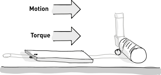
Figure 5.8Winch moving reverse
Quadrant 4: NEGATIVE TORQUE, POSITIVE VELOCITY
The fourth quadrant of speed control is the inverse of the second. It requires speed in the forward direction and reverse torque. Decelerating a large scenic piece at the end of a cue that moves from the wings to onstage requires forward speed with reverse torque. Traveling forward, the scenery builds up momentum. When the winch needs to stop the scenery, this momentum is pushing the motor forward and the amplifier needs to generate reverse torque to bring the scenery to a stop.

Figure 5.9Winch decelerationg forward
Any motor amplifier we want to use on stage needs to be capable of four-quadrant speed control and have a means to absorb the regenerated energy in quadrants two and four. Each amplifier we will discuss is capable of four-quadrant control.
Variable Frequency Drives (VFDs)
Since the AC induction motor is the most popular prime mover used in scenic automation today, it makes sense to start with the amplifier (or drive) used to power the AC motor, even though it is a complex piece of gear. As we discussed in the previous chapter, AC induction motors use the constantly changing polarity of the stator current to induce an opposing current on the rotor. The speed of the rotor is governed by the frequency of the alternating current in the stator windings. For the motor to spin faster, the frequency on the stator windings must increase. Likewise, a lower frequency on the stator windings produces a slower rotation of the rotor. The frequency of the output power is measured in Hertz (abbreviated Hz) which is the unit representing cycles per second. With just these basic facts in mind, it is clear that the amplifier must vary the frequency of the stator current to vary the speed of the motor. It follows that the amplifier used for an AC induction motor is called a Variable Frequency Drive, or VFD, since it drives the motor with a variable frequency power supply.

Figure 5.10ATV930 VFD
Varying the frequency of the stator current will vary the rotor speed, but the amplifier also needs to adjust the rotation direction of the rotor since all our machines need to run in both directions. To change direction of rotation on an AC motor the order of the phases needs to be flipped. If a clockwise rotation is produced by ordering the three phases in a sequence of black, red, blue, black, red, blue, then a counter-clockwise rotation is produced by swapping the order of any two phases: red, black, blue, red, black, blue. This is starting to sound tricky. The amplifier needs to produce three phases of alternating current at any frequency and in any order of phase. The specification seems more like a blueprint for a generator than a simple amplifier.

Figure 5.11Three-phase motor rotation
The Variable Frequency Drive (VFD) draws AC power from the electrical supply, rectifies it to DC, and then recreates an AC power wave from the internal DC power bus. That intermediate step of rectifying the AC power to DC then inverting it to AC power is necessary to easily vary the frequency and order of phase. A device that produces AC power from a DC supply is called a power inverter, and so you will also hear VFDs referred to as “inverters,” since that is part of what they do. However, simple inverters are more commonly used to run microwaves in motor homes from a car battery so calling a VFD an inverter is selling it a bit short. The VFD is doing quite a bit more work than just power inverting.

Figure 5.12VFD receives AC input power, rectifies to DC, outputs AC of varying frequency
Since the VFD is rectifying the AC to DC and then inverting the DC to AC, the original power source has little impact on the output waveform. It is good to realize that the input and output waveforms have no direct connection for several reasons. When the three stator wires of the motor are connected to the output terminals of the VFD, the forward rotation produced by the VFD may be the reverse of the direction you want. For instance, you want to press the “forward” button and have the winch track onstage, but instead it tracks offstage. Knowing that the rotation of the motor is governed by the order of the phases, you decide to swap two of the three phases. This will only work if you swap the output phases powering the motor, either at the output terminals of the VFD or inside the junction box at the motor. Swapping the phases of the supply that powers the VFD will have no effect because the VFD is rectifying the input power to DC and then inverting the DC to AC to create the output power. The input power phases and output power phases are completely unrelated. The input power is a pool of potential energy that will be completely reshaped before it becomes the output power for the motor.

Figure 5.13Swap output of a VFD to reverse direction
Since the VFD is creating the three-phase output from its internal DC bus, it can use a variety of input power sources. You can purchase a VFD that only requires 110 VAC single-phase input power, but will still produce 230 VAC three-phase output. Also, a VFD that is built for 200–240 VAC single-phase input will output three-phase power. Perhaps a little less obvious, VFDs made for three-phase input will also usually work just fine on a single-phase 200–240 VAC power source. There are limitations associated with each of these cases. A 110 VAC VFD usually has a maximum output capacity of 1 HP or sometimes up to 1.5 HP. That may be fine for smaller machines, and it’s terribly convenient to run a machine from a simple wall outlet, especially in rehearsal studios or ballroom events, but you can’t run bigger machinery. A VFD designed for three-phase input, but run on single-phase 200 V-class power, will have less output capacity. You should check the manufacturer’s specifications for running on reduced input power, but it is common for the output to be de-rated by 50%. In other words, a 5 HP three-phase VFD will only be able to drive a full 5 HP load when powered by all three phases. When powered by a single-phase supply, that same 5 HP VFD will top out at 2.5 HP. Again, this can be very useful if you don’t need full power output and are stuck in a venue with limited input power options.
Because the AC induction motor requires a moving current on the stator to generate torque on the rotor, it is inherently difficult to power the motor at low speed. As the frequency falls, the VFD has an increasingly difficult time manipulating the output power to keep high torque on the rotor. While this may not be a problem in some industrial applications where the motors tend to run at high speeds, in the theatre we often need to pull, lift, or turn heavy loads and very slow speeds. Even if the scenery moves rapidly, we still need lots of torque during the acceleration so that the movement looks graceful when the scenery starts its motion. Given that VFDs inherently have difficulty producing torque at lower motor RPM, and that scenic automation is all about short movements that start from a standstill often in full view of the audience, it is wise to plan accordingly. Build your machinery with more mechanical advantage so that the motor is spinning at near full nameplate RPM when the scenery is moving at top speed. For example, if you are faced with designing a winch to move 24 in/second, select a speed reducer that meets that speed requirement when the motor is running at 60 Hz. Imagine that to achieve the desired speed at 60 Hz, a 40:1 mechanical speed reducer is needed. It might be tempting to instead install a 20:1 mechanical speed reducer and then never run the winch above 30 Hz. While the motor will have little difficulty at 30 Hz, when programming a cue that moves only 3 in/second the VFD will be trying to push the machinery along at under 4 Hz. If that move has a lengthy acceleration ramp of several seconds, the VFD will strain to keep the load moving smoothly during the beginning of that movement.
Conversely, if you build the winch with a 40:1 mechanical speed reducer and a maximum speed of 24 in/second but find out during the rehearsal process that you really need 30 in/second, you likely won’t have any trouble. The VFD can output a faster frequency than 60 Hz to drive the motor faster than the nameplate RPM. This is perfectly fine for most inverter-duty motors. Confirm that your motor and speed reducer are rated for faster RPM, and then tweak the VFD settings for a faster top speed. There is no free lunch; the motor doesn’t magically produce more speed with the same torque. Rather, the torque will proportionally decrease as you exceed the nameplate RPM, but that usually isn’t a problem for lateral scenery movements. If a winch is dragging a wagon, or a turntable is spinning, once it has passed full-speed RPM the torque demands are greatly reduced. At that point, the momentum of the scenery will help carry the load. You need more torque at lower speed, so gear for low speed; and if you need a little extra speed, use the VFD to drive at higher RPM. Note that this approach only works for lateral movements. If you are hoisting a vertical load, the loss of torque at high speed is unacceptable. In hoisting scenarios, you have to budget horsepower conservatively for both torque and speed.
Here’s the performance chart of a Marathon Black Max 5 HP motor at different speeds:
| Hz | RPM | Torque (ft * lb) | ||
| 1 | 0 | 14.9 | ||
| 60 | 1765 | 14.9 | ||
| 120 | 3555 | 7.4 |
So far, we have considered getting the motor moving, but just as important to consider is how we stop the motor. The simplistic solution is to reduce the frequency of the electrical current and the rotor will spin more slowly. That would work if there was no inertia acting on the motor, but there is almost always some giant chunk of scenic artistry attached to a machine. The momentum of the attached load will keep the motor spinning faster than the output frequency from the VFD. As you recall from our discussion of motors, the only difference between the motor and a generator is where the force is being applied. If you energize the stator with electricity, it’s a motor, but if an external force spins the rotor mechanically, it’s a generator. The momentum of the scenery pulling on the motor will turn the motor into a generator and the generated electricity will feed back into the output terminals of the VFD. If that sounds bad, you are correct. For one thing, it won’t help stop the motor, but it will also damage the VFD if left unchecked. Instead, the VFD needs to redirect that regenerated energy to avoid damage and to slow down the motor. A dynamic braking resistor can absorb the regenerated electricity and burn it off as heat. The electrical load created by the resistor will slow the motor down and allow the VFD to maintain control of the motor’s speed.
In a lateral move, there may be enough friction in the system to slow down the scenery and eliminate the need for a dynamic braking resistor. However, that’s a tricky balance because at higher speeds and steeper deceleration rates the force of the scenery acting on the motor will increase. Slower cues could be fine, but faster cues could cause problems. In vertical movements, there’s no option. A downward movement will require a dynamic braking resistor to slow the motor since there is not enough mechanical resistance to fight gravity. In practice, I would always include a dynamic braking resistor with a VFD. The cost is minimal, and there’s no harm wiring one into the VFD, even if the particular machine in a particular show doesn’t demand it. If a movement ever causes more regenerated energy than the VFD can handle, the VFD responds by taking measures to protect against damaging itself. This protective measure lets the motor run freely until the back-voltage reaches a lower, acceptable level. This, however, can be a disaster if the scenery is allowed to coast freely in the name of protecting the VFD, especially if the momentum is large and the scenery crashes into something large enough to stop it. Even if the results aren’t so dramatic, the accuracy of the machine is greatly compromised if the VFD shuts off during the deceleration and lets the scenery coast beyond the programmed location. So, use a brake resistor.

Figure 5.14Brake resistor
Braking resistors are sized in ohms, watts, and duty cycle. The manufacturer of the VFD will offer the properly sized resistor for your choice of duty cycle. The duty cycle is the ratio of brake stopping time divided by the total cycle. So, if a move is 10 seconds long with 1 second of deceleration, it is a 10% duty cycle. However, there are maximum allowable times for the duty cycle. A 10% duty cycle resistor could not function under load for an hour even if that was followed by a 9-hour rest. The manufacturer will provide maximum operating times for the duty cycle. Also, there is a difference in duty cycle rating for lateral deceleration versus hoisting. In a vertical hoisting, or overhauling, application the brake resistor is constantly working during a downward movement, so the braking resistor needs either shorter cycles or a higher duty cycle. Most of the time, a production can work with low duty cycles since our cues tend to be short with long recovery intervals. The exception is technical rehearsal where a movement might be run over and over and over. At that point, a judgment call is needed to determine if a bigger, more expensive resistor is warranted or if the rest of the production team can work within the limitations of the equipment.
Braking resistors can get very hot. If they are mounted inside a cabinet, they require good ventilation so they don’t overheat nearby components. The cabinet should be marked with a warning about the hazardous heat and burn risk. If they are mounted outside of a cabinet for improved airflow, you should provide a protective cover to prevent burns and damage to the wires connecting the resistor to the VFD.
In my years of producing automation equipment and providing technical support, I have heard a lot of understandable confusion between dynamic braking resistors and mechanical, spring-set brakes. I always recommend that machinery built for the stage should be fitted with a mechanical brake that engages automatically when power is removed. As we discussed in the chapter on machinery, these brakes are engaged by springs that lock the shaft of either the motor or output drive shaft. These brakes are meant to hold a stopped load, but not to decelerate a moving load to a stop. A dynamic braking resistor is an electrical device that decelerates the load to a stop so it can be held by the mechanical brake. It may sound redundant, but omitting the dynamic braking resistor because you have a mechanical brake is analogous to remove the brake pedal from a car and just using the parking brake. Both are needed and have different, necessary functions in the system, but have no effect on the other.

Figure 5.15Mechanical brake vs. dynamic braking resistor
There are three common tiers of VFD performance that are mostly distinguished by their ability to control speed tightly, generate low-speed torque, and provide additional input/output features. In order of performance, the available types of VFD are: Volts/Hertz (or Volts/Frequency), Open-loop Vector, and Closed-Loop Vector. Tight speed control and low-speed torque are fundamentally related. Additional input/output features are added to high-performance drives to make the higher price justifiable. If you require better motor performance, it is reasonable for the manufacturer to assume you will benefit from more control features. If you need precise motion, you probably need a way to control that motion. In industry, the use of VFDs ranges from HVAC blowers that need simple speed regulation within a limited range to full robotic applications. Those applications may need full-torque from very low speed to maximum speed. The tiers of products from good, better, best are designed with this range of applications in mind.
The type of VFD refers to the control method used to regulate the speed of an AC induction motor. As we’ve seen, controlling the speed of the motor is no easy feat, and there are different methods that can be employed to regulate speed. We have been focusing solely on varying the frequency of the power waveform, but that is a little naïve. As the motor is loaded with a resisting force, the voltage and current will also fluctuate. To maintain a set speed, the VFD will vary the frequency and voltage to the motor. As the motor spins more slowly, it gets harder and harder for the VFD to maintain speed under a full load. Each drive will be rated for a speed control range within which it can safely drive the motor before the motor overheats or speed control is effectively lost. This speed control range is given as a ratio such as 40:1 or 1000:1 and it represents the lowest speed possible to drive the motor at full-torque. To calculate the lowest possible RPM, divide the nameplate RPM of your motor by the left-side term of the ratio. In other words, a VFD with a 40:1 speed control range can drive a 1800 RPM motor down to 45 RPM (1800 / 40), while a 1000:1 speed control range can drive the motor under full load all the way down to 1.8 RPM (1800 / 1000). As you step up in quality of drive, the speed control range grows until you reach the nirvana of full-torque at zero-speed. Keep the speed control range in mind if you need to purchase a VFD. This is a very real, very important specification.
Volts/Frequency or Volts/Hertz
Volts/Frequency (V/f), or Volts/Hertz (V/Hz), is the simplest control method for a VFD. It maintains a simple, constant ratio between voltage and frequency of the output. This ratio can be customized by parameters in the drive, which are typically set either by a keypad on the drive, or via a PC over USB, Ethernet, RS485, etc. The ratio can be manipulated to have a higher torque at the low speeds which can help get a load moving, but shouldn’t let you be fooled into thinking this type of VFD is a good choice. The drive has no feedback from the motor to regulate the speed; instead it is operating blindly and sends out the same power to the motor whether it has no load or full load.

Figure 5.16Yaskawa VFD
As an example, the G7 drive from Yaskawa is a high-performance VFD that can be set to operate in any of the three control modes but offers a speed control range of only 40:1 in V/f mode. Once you dip below 45 RPM, or 1.5 Hz, the drive can’t offer any substantial torque to move the load, which means that getting a scenic element rolling from a standstill will be jerky until the motor reaches at least 45 RPM. It will look a bit like popping the clutch on a car with manual transmission heading uphill.
Open-Loop Vector
The next step up from V/f control is Open-Loop Vector Mode. V/f gets no information from the motor to compensate for changes in load, and Closed-Loop Vector uses a dedicated sensor to track the rotor position. Open-Loop Vector covers the middle ground; it does not require a dedicated sensor on the motor to track the speed output, but doesn’t blithely output power without considering how the motor is reacting. Instead, Open-Loop Vector drives will estimate the motor speed by tracking the stator current and make an educated guess about how the output power should change to keep the motor moving at the commanded speed.
Continuing our example of the Yaskawa G7 VFD, when it is set to Open-Loop Vector Mode the speed control range jumps from 40:1 (V/f) to 200:1. Rather than being limited to a lowest speed of 45 RPM, the same motor can be driven as low as 9 RPM without overheating or losing effective speed regulation. To achieve this additional performance, a VFD will usually have an auto-tuning procedure that must be executed. After setting parameters that inform the drive of the attached motor’s current, voltage, and nameplate RPM, the VFD will probe the motor response by sending short bursts of power to the stator. Typically, this can be done by either moving the motor or keeping the motor stationary. The results are usually more accurate if the motor can move freely without an attached load, but are sufficient either way. If a mechanical brake is being used to lock the rotor, the brake will need to be released for the auto-tuning to work. Because the brake will be released during auto-tuning, make certain that the load is secured or removed before beginning tuning.
Closed-Loop Vector
The pinnacle of performance for a VFD is Closed-Loop Vector control mode. In this mode, a VFD requires a sensor on the rotor to detect exactly how fast the motor is moving. It uses that sensor data to precisely adjust the voltage, current, and frequency to maintain the requested speed. Very good torque control at low speed, or even zero-speed standstill, is possible with Closed-Loop Vector control. This precision comes with the cost of a more expensive VFD as well as the added cost and complexity of adding a sensor, usually an encoder, to the motor. However, the expense and complexity of adding an encoder for speed regulation is probably not a factor, since a machine that is destined to run cues will need the same encoder data for position control when connected to a motion controller. Many manufacturers offer VFDs that operate in Open-Loop Vector mode but can achieve Closed-Loop Vector control with the optional module that can be added at any time. A prudent purchasing choice is to buy an Open-Loop Vector drive, see if the practical performance is good enough for the intended effect and, if not, then add a Closed-Loop Vector module.
Following the example of the Yaskawa G7 VFD to its inevitable conclusion, in Closed-Loop Vector mode the speed control range climbs to an impressive 1000:1. At this rating, the VFD can run a motor under full-load at the creeping speed of 1.8 RPM. In practice, the drive can produce full-torque at zero-speed, allowing for the VFD to hold a load steady at a standstill, but full-torque at zero-speed cannot be maintained indefinitely. To produce torque, the motor consumes electrical current, which produces heat. In a fan-cooled motor the fan is connected to the rotor and the rotor must spin to cool the motor. Holding at zero-speed, the rotor is not turning the fan and therefore the motor cannot cool itself. This is fine for a short time, but if the load is meant to be held for a lengthy period, a mechanical brake should be engaged and the amplifier turned off.
VFD Features and Settings
When you are first presented with the operation manual for a VFD, you may be a bit stunned at the size of this instruction manual and the dizzying array of options. Most drives will have a keypad with some buttons and a readout with a somewhat painful menu system that allows you to adjust the wide variety of parameters available to configure. Many of the parameters are optional, or have sensible defaults, but there is usually a core set of parameters that need to be configured. If you are assembling your own automation system, integrating a third-party drive to a commercial automation system, or just need to reconfigure a VFD that was included with such a system, you should be familiar with the basic parameters and understand how they affect performance, motor protection, and system safety. Every manufacturer has their own parameter list, each with their own vocabulary, but there are common themes among them all. If you understand the concepts, you can sift through the manufacturer’s documentation to find the parameter you need.
To generate the correct output power the VFD needs to know what your motor requires. The basic settings that you should find and set for each motor you connect to the VFD are listed below. This is not an exhaustive list, but this is the minimum number of settings you need to research and configure in the VFD.
•Motor current – The maximum allowable motor current must be set in the VFD. This is an important protection feature that is one of the safeguards you can employ to prevent damage to the motor from overload. A motor that is bogged down with a heavy load or jammed on an obstruction will draw excessive current and ultimately burn itself up. While fuses can be installed to prevent catastrophic current draw, the VFD will also offer more fine-grained control over the allowable current levels. Not only can you set the maximum current, you can also govern the amount of time that an excessive current can be drawn before shutting off the motor. All motors will draw more current when starting up before settling down mid-move, and the VFD gives you control to define how much excessive current is safe and expected versus when the excessive current level indicates a problem.
A VFD is rated by the maximum horsepower output, but can be used with smaller motors. For example, 5 HP VFD typically can be used with a 3 HP motor, although each manufacturer has specific recommendations about the minimum horsepower. When you run a smaller motor, it is critically important to remember to reduce the allowable current for the motor. If a VFD is unplugged from a 5 HP machine and plugged into a 3 HP machine, it will continue to allow 5 HP worth of current to flow to the motor. Should the 3 HP motor get jammed or overloaded with weight, it will be allowed to draw too much current, burn up its windings, and cease to function. To protect against equipment damage, and potential fire risk, the allowable current should be reduced in the VFD settings and appropriate circuit protection should be installed with the manufacturer’s recommendation for the size of the motor.
•Motor voltage – The VFD needs to know how much voltage to provide to the motor; this should match the voltage stamped on the nameplate of the motor.
•Motor RPM or frequency – There is usually a parameter for the base RPM, or nameplate RPM of the motor. This could be expressed in RPM or frequency, but either way it represents the rated full-speed for the motor at full-load. Additionally, there is usually a maximum RPM or frequency that can be entered to allow the motor to be run above nameplate. Again, this information is usually available on the nameplate of the motor. Sometimes this setting will actually allow the motor to be run faster than 60 Hz, sometimes this is just an upper-level cap and a second parameter needs to be flipped on to let the motor achieve that speed.
•Starting frequency – The VFD defines a minimum frequency that should be considered a real movement. If you are connecting a motor that has a speed range lower than the VFD, you can raise the starting frequency to match the motor. You might also raise the minimum frequency to match the minimum speed expected from the control signal if you are connecting the VFD to a motion. We’ll be discussing motion controller signals a lot more in later chapters.
•Braking resistor – The VFD will have parameters to enable a braking resistor. The resistor may be built into the VFD, or, more likely, is external. Either way, it needs to be enabled for the drive to shunt regenerative energy through the resistor to assist with high-inertia deceleration or descending load.
•Brake resistor duty cycle – As discussed, brake resistors can be purchased with different duty cycles and the duty cycle needs to be described to the VFD. The VFD can track how much energy is being pumped into the resistor and will avoid burning up the resistor when it is taxed too heavily. Make sure to read how the VFD plans to protect the brake resistor in the installation instructions. Usually, it protects the brake resistor by allowing the motor to freewheel for a while, which is likely not ideal for other safety concerns. The VFD should be configured to engage the mechanical brake and shut-off rather than free-wheel. It’s important to realize that if a protective feature doesn’t have a dedicated sensor, it is being calculated. In the case of the brake resistor, the drive is trying to keep the resistor from getting too hot, but it is doing so based on the power it shunts to the resistor. Alternatively, the resistor may be equipped with a thermal sensor to send the actual temperature to the drive.
•Brake output – The VFD may have a dedicated output for firing a spring-set mechanical brake or it may have a general-purpose output that can be used to trigger the mechanical brake. These outputs do not typically operate the brake directly, instead the output can be used to activate the coil of a contactor to power the brake. If the motor is running, the brake should release. If the motor stops, the brake should engage. It sounds obvious, but make sure the thing that is controlling the motor is also controlling the brake because the operation of the two mechanical devices is so tightly intertwined. It’s tempting to think that the “GO” signal that runs the motor can be wired in parallel to trigger a brake release, but this is incredibly dangerous. The VFD might stop the motor for a variety of fault conditions at any time. The settings outlined above highlight a couple of easy ones: motor over-current and brake resistor over-load. There are many scenarios, but consider a stage lift being operated by a hoisting winch which begins to raise and gets jammed because of a misalignment of the vertical guides. The VFD notices that too much current is sent to the motor and shuts off the motor. If the holding brake for the lift is run by an independent control circuit, the hoist will drop the lift since it may be unaware of the VFD shutoff. Or, the power wires to the lift motor have been severed and the VFD has no control over the motor. The VFD has settings that can detect these problems, but it must have control over the mechanical brake to safely react to such problems.

Figure 5.17VFD controls brake through contactor
•Control mode – A higher performance VFD will have options to operate at lower performance levels. If you have a Closed-Loop VFD, you can choose to operate in V/f mode, Open-Loop Vector, or Closed-Loop Vector mode. A VFD that is dedicated to a single machine will probably be set to one mode and left that way forever, but if you need to repurpose a drive show after show, it may be necessary to switch between modes. For instance, a winch might be run in Closed-Loop Vector mode because it has a motor-mounted encoder that can be used for both speed regulation and position control. However, the turntable machine may only have a positioning encoder that is mounted to the turntable and there isn’t a speed encoder on the motor. In that case the drive might be reconfigured from Closed-Loop Vector to Open-Loop Vector to run the turntables.
•Acceleration – The VFD will have configurable acceleration and deceleration for a smooth start and stop. This can be useful depending on how the VFD is utilized by the motion controller. If the cue parameters are fed to the VFD then the acceleration can be sent to the VFD. On the other hand, if the motion controller is responsible for generating the ramp up and ramp down, the acceleration in the drive will be need to be set to zero so that the motion controller has full control over the speed setting. In that situation, the VFD is just tasked with keeping up with the command signal from the motion controller.
•Speed control signal input – Though we haven’t had a chance to dig into control systems yet, it is a safe bet that the VFD will need to communicate with a motion controller that will tell the drive how fast to move. All VFDs will have a simple provision to run the motor from the keypad, or a simple potentiometer knob, but you will need more than that. It is important to match the speed control input signal of the VFD with the motion controller speed output. Common options are:
•0–5 VDC – In this mode the motor speed will follow an analog control signal from 0 VDC (stopped) to 5 VDC (full-speed). Anything in between the extremes will be proportional. If the full speed is set to output 60 Hz, then a command signal of 2.5 VDC will output 30 Hz. The direction of the motion will be determined with a separate switch closure for forward or reverse.
•0–10 VDC – This signal is just like above, but using a higher voltage range.
•+/-10 VDC – With a bipolar signal, the VFD still follows an analog speed command, but the direction is described as well as speed magnitude. 0 VDC is still used for a stopped motion, but +10 VDC will be full-speed forward and -10 VDC will be full-speed reverse with a speed signal between the extremes producing a proportional output. There is no need for separate forward and reverse direction signals since the voltage polarity is used to describe the direction. However, there is still a switch closure used to “Enable” the drive. The “Enable” switch prevents unintentional VFD motion from interference on the control wires. The controller closes the Enable signal when it wants the VFD to pay attention to the speed signal.
•4–20 mA – A current loop signal is similar to the unipolar voltage signals, but varies the current instead of voltage. The current loop is more common in sensor feedback but can be used for speed control as well. In this signal, a current of 4 mA (.004 amps) is equivalent to stopped; 20 mA indicates a full-speed movement. Since a steady current flow is always used, the drive can detect when the signal is lost completely and alert the control system of a wiring problem.
•Digital – A variety of communication options is usually available from RS485 to CAN to Ethernet/IP to Profibus/ProfiNet to EtherCAT, or a few proprietary protocols. These protocols can be used to command the speed of the drive and communicate status information to the control system. If the automation system can be standardized on a single digital protocol it can greatly simplify implementation, but at the cost of flexibility. As we’ll see, the analog speed signals can be more versatile in a heterogeneous system that has a mix of machinery and multiple amplifiers from varying vendors.
Most VFDs will have an assortment of inputs and outputs that can be used for low-voltage control circuits. Some of these I/O points may have a designated purpose, or be configurable for different purposes. What this means is that even low-end or mid-range drives can be used as a self-contained control system for simple needs. For instance, a couple of pushbuttons and limit switches might be all you need to create a simple roll drop controller that can be raised and lowered with fixed positioning. More sophisticated drives may have an embedded PLC (programmable logic controller) or a simple motion processor that can be used to set speeds and positioning for a rudimentary cueing interface or incorporated into a network for more sophisticated motion.
The outputs of the VFD can be used to operate a mechanical brake, as discussed earlier. The output can also be used to alert the control system of a fault condition. There are many faults that can cause the VFD to stop moving the motor, and it’s good to inform the automation operator of any trouble as soon as possible. Outputs can also sometimes be configured to daisy chain drives in a master/slave configuration or set up an electronic gearing ratio between motors for more complex motion.
The VFD may have inputs for Safe-Torque Off (STO) which, when coupled with the proper safety relay, can be used for Emergency Stop circuitry without the need for large expensive contactors. However, this circuitry may only be rated to SIL2/PLd safety levels, which may or may not suffice for your circumstance. We’ll talk a lot more about safety and applicable standards throughout the book, but it’s worth a mention here.
Tips
There are a few tips, tricks and gotchas to keep in mind when working with Variable Frequency Drives. This is a grab bag selection of advice that I wish I had known starting out.
Cable Lengths and Line/Load Reactors
Each manufacturer will have a recommended maximum cable length for the power cord that runs between the VFD and the motor. This distance can sometimes be extended with a piece of equipment called a “load reactor” to help reduce unwanted distortions in the power waveform. In such a case, the load reactor should be installed on the output side of the VFD. Similarly, the VFD can produce unwanted noise on the power feeding the drive. In such cases, a “line reactor” can be installed on the input side of the drive.

Figure 5.18Line or Load Reactor
You can run several AC induction motors from a single VFD and achieve reasonable synchronization. This works best when the motors are mechanically linked together. For instance, placing two motors diametrically opposed on a turntable and powering them from a single VFD can be a good way to prevent slip when the turntable is eccentrically loaded. On the other hand, this doesn’t work as well with an unconstrained object. The motors are not made precisely enough to guarantee precisely matched speed, so a pair of hoists two-fer’d into a VFD would not necessarily keep a batten level throughout the full range of travel.

Figure 5.19Multiple motors on a single VFD
Some VFDs aren’t recommended for higher level control modes with multiple motors attached, and will be run in V/f mode, which is naturally less than ideal. Additionally, current limiting is a tricky problem with multiple motors. The drive needs to provide enough current to supply the total horsepower of the sum of the motors. However, if a single motor fails or becomes disconnected, then the rest of the motors would be able to draw dangerously high current. So each motor must be protected individually with separate overload devices to insure the drive is set to protect the entire system. It’s easy to see how this arrangement can cause issues during a performance if one of the motors trips a circuit breaker but the rest do not. The protective devices will need to be wired to trip together, inform the drive that there is an issue, and force the drive to send that fault information up the chain to the control system. All this is possible, but like most automation design, it is important to anticipate how the system reacts when something fails.
If your VFD has a keypad, it’s a good idea to get a spare. The keypads can store all of the setup parameters conveniently inside and then be recalled at any point to configure another VFD. If you have spent a lot of time figuring out the drive settings for a stable of winches, make a copy and keep it in your kit of gadgets. Then, when a drive fails and has to be replaced, or you grow your inventory, it is easy to replicate the working configuration. In the fast-paced environment of a typical theatre, it’s worthwhile to make it easy to swap equipment out.

Figure 5.20ATV930 keypad
The keypad is a great diagnostic tool for a problematic axis. It can store a collection of the fault history, allowing you to retrace the most recent reasons a drive may have failed to perform as expected. Sometimes the error codes are nice and verbose; sometimes it’s a cryptic code. If your drive is like the latter, keep a cheat sheet of the error codes handy in the automation desk. After error codes, the most common thing I look at on a keypad is the current draw of the machine. Having a current meter built into the VFD is a great preventive maintenance tool. When the machine is first being tested, note the current draw. Periodically check the current draw and log it so you can get an early warning of a problem. If the current starts to rise over the weeks of a production, that means that the motor is working harder, which in turn means that something else in the system is wearing down. At that point, start looking through all of your mechanics to see what is causing trouble.
Common Brands
There are a lot of manufacturers making VFDs. While I can’t include a list of every make and model, I will share some of the popular brands and models that are commonly used. Beyond the quality of the components, it is important to consider the quality of the technical support. Some manufacturers are very responsive and helpful; others not so much. A good way to feel confident in the support is to find a local representative and talk through your needs with their application engineer.
•Automation Direct – Renowned for low prices and quick shipping, Automation Direct is very popular in lots of budget-conscious theatres. The GS3/Durapulse VFD is incredible value, can be run in any control mode, has very good documentation, and the company provides accessible technical support. All that said, the low-speed performance is sub-par when compared to drives that cost 2x or 3x more… go figure.
•Mistubishi – A favorite at my company, Mitsubishi has impressive value with freakishly good Open-Loop Vector performance, as well as options to cover a wide range of price/performance ratios. We use a lot of the A700/A800 series VFDs in our Stagehand controllers, and the lower-level D700 series is found in our Deck ChiefTM. The A700 series has a PLC built-in that can be used for motion control, or in our case it is used for handling slightly complicated brake switching logic. The documentation can be obtuse, and the parameter layout is schizophrenic, but the company support is good and the performance is great for the cost.
•SEW-Eurodrive – Best known for their AC gearmotors, SEW also has a full complement of drives. The MoviTrac and MoviDrive are excellent choices and can be bundled with a gearmotor at discount. The MoviDrive is a powerhouse, with lots of control features, and the ability to run either AC induction motors or brushless servos. The MoviTrac is a step below, and has a reduced cost, but with the optional add-ons that can be selected it can achieve some of the MoviDrive’s capability.
•Emerson/Control Techniques – This is a high-end product offering that was famously used in some expensive scenic automation systems. They offer a range of drives in their Unidrive M series to address needs ranging from simple speed to control to onboard motion control.
•Siemens – A favorite of many, Siemens makes lots of automation products including drives. I’ve heard nothing but good things about the products.
•Yaskawa – Though Yaskawa may lack some name recognition, they manufacture drives for several other brands and have a solid product lineup.
•Schneider – Schneider Electric owns many popular brands including Square D, Telemechanique, and APC. They supply just about every electrical component used in an automation system and VFDs are no exception. They have a range of VFDs from simple V/f drives to Closed-Loop Vector drives with on-board motion processors.
Permanent magnet motors have declined in popularity in scenic automation. The quiet operation of AC induction motors, expense of DC motors, and dropping cost of VFDs have all contributed to the shrinking ranks of DC machinery. Even so, there are a lot of old DC machines still sitting in the wings of theatres across the country, and sometimes it may make sense to build new DC machinery. For those cases, it’s good to know a bit about the DC Regen Drive.
The name DC Regen Drive is the common shorthand for a Regenerative Drive. Regenerative refers to the drive’s ability to dynamically slow a motor by using the generated current as a counteracting force and operate in all four quadrants of speed control, as discussed earlier in this chapter. There are DC drives not capable of four-quadrant operation, but those aren’t useful on stage.
Because of the simpler nature of DC motors, DC amplifiers are inherently simpler than the VFD used with AC motors. A VFD will have hundreds of configuration parameters that can be adjusted either through the programming keypad or from a PC, and the operation manual will likely be at least a couple hundred pages long. By contrast, DC regen drives typically have fewer than ten parameters that can be adjusted with a small screwdriver on a trimpot, and the manual looks like a pamphlet that might be handed to you on a subway platform. The amplifier takes a power input, usually single-phase 110 VAC or 220 VAC, rectifies it to DC and varies the output voltage to vary the speed of the DC motor. The accuracy of the speed control varies depending whether the drive is using armature feedback, sensing the current on the rotor, or is receiving pulses to indicate the motor rotation (if a dedicated tachometer is attached to the rotor).
A DC regen drive is sized by the output horsepower and the motor voltage. DC motors range in size from very tiny sub-fractional motors to many horsepower, but in practice we don’t see much more than 5 HP motors on stage these days and a 3 HP motor is more typical. Common voltages are 12 VDC, 24 VDC, 90 VDC, and 180 VDC. The most commonly used motors are 90 VDC and 180 VDC if the amplifier is to be plugged into the wall, and 12 VDC and 24 VDC more often used in battery-operated situations. A drive will usually accommodate a wide range of horsepower. For instance, the venerable Minarik RG5500U-PCM can operate from ¼ HP to 2 HP, though that range is split in two parts. The drive can power ¼ HP to 1 HP 90 VDC motors with a 110 VAC input, and 1 HP to 2 HP 180 VDC motors with a 220 VAC input.
The wide voltage and horsepower operating range of a DC Regen Drive means that you must take some steps to safeguard small motors from damage, as well as prevent large motors from being under-powered. First, the drive may have physical configuration switches that should be set to match the input power supply. The Minarik RG5500U-PCM has a pair of power input switches on the main amplifier circuit board, and a third switch on the control interface board. It also has different wiring terminals for the two input voltages. Next, the output voltage may have selector switches to pick either 90 VDC or 180 VDC. Finally, to protect the motor from drawing too much current and burning out, fuses must be installed if the drive doesn’t have electronic overload protection. Sometimes the drive has fuse holders on-board; sometimes external fuse holders must be provided. Either way, a properly sized fuse of the correct type, as specified in the manufacturer’s manual, should be used. That fuse must be changed to match the motor anytime the drive is connected to a new motor.

Figure 5.21DC regen drive with input fuse
The DC regen drive doesn’t use the large braking resistors of a VFD. Instead, the generated voltage from the motor during a deceleration is used to directly slow the motor by feeding that voltage back into the motor in opposition to the load torque. The heat generated in the process is mostly dissipated through the motor’s windings, with some energy converted to heat on the braking circuitry built into the DC drive. At higher horsepower operation, the heat dissipated through the drive chassis can be substantial. To prevent any damage to the electronics, a heatsink is usually available from the manufacturer to safely disperse the heat. Check the documentation of your drive to find out at what horsepower a heatsink is recommended.
While DC regen drives lack the vast configuration options of VFDs and brushless servo drives, there are typically options built into the amplifier for acceleration and deceleration, maximum speed, and torque limiting. These options are usually set by adjusting trimpots on the circuit board with a small screwdriver. If the drive is being used with a motion controller, the acceleration and deceleration should be turned off so that the control signal from the motion controller is followed precisely without any lag introduced from the acceleration or deceleration ramps.

Figure 5.22DC regen drive trim pots
Assuming the drive will be connected to a motion controller for cueing, the DC regen drive will need inputs for a speed command signal. Unlike the VFDs, DC regen drives do not typically have a suitable input built onto the drive. The drive may have inputs for a speed knob, but that should not be connected to an external controller. The voltage levels at the control terminals on the amplifier may be dangerously high and can damage a motion controller irreparably. Not that I’ve ever done that… a second time. Instead, the manufacturer will offer an add-on module that isolates the drive from the controller. In the Minarik product line, the “-PCM” suffix is used to indicate this isolation module known as the Process Control Module. KB Electronics drives offer the SI-5, or Signal Isolator. If you are unsure whether the control inputs on the drive are isolated, contact the manufacturer. With a signal isolation card installed, the DC regen drive will follow a variety of analog speed command signals. Unipolar 10 VDC, bipolar 10 VDC, and 4–20 mA are all common signals. Lacking are usually any of the digital speed signals found on the VFD. However, analog speed signals are very common across all amplifiers and can be an easy way to connect a motion controller to a variety of equipment, so the lack of a digital signal input shouldn’t slow you down.
Common Brands
The list of manufacturers of DC regen drives has shrunk a bit over the years, but here is a list of some of the popular choices:
•Minarik – As referenced above, Minarik produces quality drives at affordable prices. They have a wide range of drives available, and are helpful when you need to find the right match for a motor with a specific set of features.
•KB Electronics – Another common manufacturer of good drives is KB Electronics. They offer a similar range to Minarik, and often the choice between the two comes down to vendor relationship, price, or availability.
•Dart – Dart controls are most often recognized for being the DC drive in the Grainger catalog making them easy to get.
The key benefits of brushless servo motors are great power in a small physical package, constant torque throughout the speed range, and bursts of peak torque that are several times higher than the continuous rating. Inside the Brushless Servo Drive, power supplied from an AC source is rectified and then pulsed out to the windings in the stator, which creates a magnetic field to spin the magnetized rotor. The input power can range from single-phase 110 VAC to single-phase 220 VAC to three-phase 230 VAC to three-phase 460 VAC. A drive built for single-phase input may be able to operate from the low- to high-voltage range, with just a loss of output speed. This is a pretty handy feature if you need a compact system that can be run from common wall power.
The brushless servo amplifier has a lot in common with a Closed-Loop VFD. The amplifier reads encoder input from the rotor and varies voltage and frequency of the output power to move the motor and variable speed. In fact, the technology inside is so similar that some high-end VFDs can also drive servo motors, or can have that capability added with an optional module. As such, the drives have similar complexity and configurability. Where the VFD can operate with or without encoder feedback, depending on whether the control mode is Open-Loop Vector or Closed-Loop Vector, the servo amplifier must have an encoder generating rotation pulses to spin the rotor. As you recall from our discussion of the brushless servo motor in the previous chapter, there is no connection between the stator windings and the magnets embedded on the rotor and it is up to the drive to calculate when to flip polarity on the stator windings to create rotary motion. The drive relies on the encoder feedback signal for that calculation to time the electrical pulses precisely right. A guy I worked with years ago, on our first ill-fated servo project, had a great way of thinking of a servo drive and motor. Paraphrasing his concept, the motor is so dependent on the drive that conceptually they are two halves of a single device connected by a cable. When you realize that the motor cannot even natively spin without an amplifier, his explanation rings true. An induction motor can run off of an electrical service coming out of a wall socket. A DC brush-type motor can run off of a battery. A brushless motor is a paperweight without a complex piece of electronics.

Figure 5.23Servo motor and drive
A benefit of requiring a sophisticated amplifier for operation is that you get a lot of features packed into the amplifier. Most servo amplifiers can do some simple, or even advanced, motion control without a separate motion controller. If you were designing a standalone system, it is easy to imagine developing a software cueing interface that commanded a network of servo amplifiers directly without a discrete motion controller, instead of just using the motion control capabilities built into the drive. This probably wouldn’t be a great choice for a general-purpose, modular system since you probably don’t want to limit yourself to only using brushless servo drives from a single manufacturer, but it’s a good option to keep in mind for standalone effects.
A drawback to the high-speed, high-current pulses of power that the drive injects into the motor is electrical noise. I don’t mean audible noise, rather electrical interference in the form of radio waves emanating from the drive and cabling. The high-energy pulses, at high-frequency, can turn your automation system into a broadcast radio station. In fact, in my early 20s I had the pleasure of working on a first-generation automation system for a commercial shop that was built around servos. Prior to this project, the shop had primarily been using brush-type DC motors and DC regen drives. A little cavalier, and a little dense, we rushed headlong into the new technology without doing all of our homework. During load-in, we had a never-ending stream of faults and failures in the equipment. One bleak night/morning, in the fourth week of a two-week load-in, I was chasing down a problem with another technician. To find the problem, I was at the automation rack flipping switches to turn the motor on and off rhythmically while my buddy was on stage looking at the machine. My partner in crime said, “Whoa, you gotta come see this!” We swapped places, and I saw that every time the drive enabled, different lights in the front of house were flickering on and off. We were generating enough interference to corrupt the nearby DMX lines. Yikes!
Old war stories aside, you want to be really conscientious about limiting electrical interference when working with servos. Proper grounding techniques are essential for reliable operation. Well-shielded cabling, that are properly terminated and do not create ground loops, are required. Keep your cable distances between the drive and motor as short as practicable, and, if possible, use pre-made cabling from the manufacturer. Read all the manufacturer’s recommendations for cabling and pay close attention to the recommended cable length limits, which are often less than 50 ft.
For dynamic braking, servo amplifiers require a braking resistor just like a VFD. The same characteristics apply: the resistor will be rated for the motor power in kilowatts with a duty cycle that governs how long of a rest interval is required between peak usage. Just like the cables between the motor and drive, the brake resistor leads should be kept as short as possible.
To take advantage of the benefits offered by brushless servo motors, an amplifier must be tightly matched to the motor. In AC induction motors and DC permanent magnet motors, there isn’t any need to get both the motor and drive from the same manufacturer. With servo motors, however, the components are so tightly integrated that there would have to be a really compelling reason to source the motor and amplifier from different vendors. It is much simpler to get the whole package from one supplier.
All the companies mentioned above that build quality VFDs also have servo amplifiers, and sometimes they are the exact same product. There are other companies that focus solely on servos, but the previous list is a good starting place, and those vendors have the benefit of offering VFDs too.
Stepper motors spin in precise increments. Every time a set of coils in the stator is energized, the rotor clicks into alignment. The degree of rotation is specified by the motor step resolution. The stepper drive takes an input DC voltage and outputs the pulses to the proper coils in sequence to advance or reverse the motor.

Figure 5.24Stepper motor and indexer
Stepper drives need to be fed a diet of DC voltage for powering the motor, and a stream of pulses to command the speed and amount of rotation. The power source can be built into the drive, or commonly provided as a separate component. Stepper motors can operate over a range of voltages. For instance, a NEMA 34 1.8° two-phase stepper from Schneider includes torque/speed curves for operating at 24 VDC, 45 VDC, and 75 VDC. Since the drive is powered by an external power source, you can buy a DC power supply with a voltage that matches the speed/torque you want.
The speed command signal for a stepper drive is very different than the signals we’ve looked at for the other drives. Rather than following an analog voltage or current, stepper drives typically follow a signal known as “step + direction.” The direction portion of the signal is pretty easy: a high signal is clockwise and a low signal is counter-clockwise on the direction input. The step signal is a series of pulses that alternate high to low. For each transition from high to low, the motor will advance one click, or step. The faster the steps are sent, the faster the motor advances. This should not be confused with a PWM (pulse-width modulated) signal. PWM is a way of simulating an analog signal digitally by turning a voltage on and off while varying the duty cycle. Step + direction uses pulses as a counting mechanism for the distance to rotate, while the velocity of the pulse train describes the speed of rotation.

Figure 5.25Step and direction vs. PWM
Generating the pulse train that describes speed and distance to a stepper drive is the job of an indexer. The indexer more specifically fits into our Pentagon of Power in the Control role, but it’s worth mentioning here since many stepper drives have in-built indexers. The indexer can be programmed to create a movement of a certain distance and speed, usually from a computer, and it will break that task up into a series of pulses to send to the stepper drive. Not all stepper drives have an in-built indexer, but many do and it makes simple cueing very fast. A complete stepper system has a motor, power supply, drive, and indexer. Using a computer with a communication link to the indexer, probably a serial link, you can program the motor to advance 3000 steps at 300 steps/sec with an acceleration of 100 steps/sec/sec, hit “send” and the motor will smoothly accelerate, run, decelerate and stop. It’s a very satisfying experience to get such sophisticated motion so easily and inexpensively.
Sounds perfect, right? So, why aren’t we all using steppers all the time?
Well, notably absent from the stepper system is a feedback sensor that informs the drive or indexer of what the motor is actually doing. Instead, the system is completely “open-loop” – commands are sent off and assumed to work perfectly. If the motor stalls, the system has no way to compensate. Furthermore, steppers are limited to relatively low torque, making it stall easily. And to add insult to injury, if you look at the torque/speed curve of a stepper motor you will see the disheartening slope showing that the stepper motor steadily loses torque as speed increases. They are also audibly noisy, producing an easily identified whine while running. This doesn’t mean that steppers are never a good idea, just that they are not usually a good idea. I find them useful in smaller prop effects, but not in machinery destined to lug scenery around.
Common Brands
There are a lot of stepper motors and drives out there, but here are a couple to consider.
•Schneider – Schneider has a line of traditional steppers and drives. In addition, they have a line of stepper motors with all the drive electronics built into the motor for a very compact solution. They also have a “closed-loop” stepper that includes an encoder. That is a half-solution to the problem of a stepper stall. The system can detect a fault, but can’t adjust for a stall.
•Automation Direct – Automation Direct has a very affordable of steppers and drives. They have a line of drives without indexers, and a line with indexers that can be programmed over a serial link.
•Oriental Motor – Oriental Motor has an affordable line of steppers with a range of drives from simple to sophisticated.
Variable-Speed Hydraulic Pumps
So far we’ve focused on powering electric machinery, but we should explore the options for powering hydraulic machinery too. The principles are similar: we need to produce a controllable flow of energy from a source to the actuator. However, instead of sourcing power from the electric supply, we need to get our power from a tank of oil; and instead of spinning a motor at variable speeds with electricity, we need to push a cylinder at variable speed by regulating oil flow. There are two primary concepts we can employ to create a variable flow of pressurized oil: pump the oil at variable rates, or pump the oil at a fixed rate and variably restrict the flow with valves. Since we’ve been focusing on variable speed electric motors, let’s look at variable speed pumping first.

Figure 5.26Variable speed hydraulic pump
To pump oil at variable rates, a hydraulic pump is attached to a motor. The motor is then attached to a matching drive. If an AC induction motor is used to turn the pump, then a VFD should be used. If a DC motor is used, then a DC drive should be used. As the pump turns, it will push pressurized oil out from the tank. As the motor spins faster, the velocity of the oil will increase. Slowing the motor down will slow the oil flow. If the motor stops, the oil flow stops. The pump only runs when the machine needs to move, and the speed of the machine is matched by the speed of the pump.
With a variable speed pump our oil flow is cruising through the system at variable flow rates. The next step is to introduce a directional valve to push the oil into the correct spots. Consider a scissor lift. To make the lift go up, the oil should be pushed into the bottom, or cap-end, of the cylinder. As the oil is squeezed into the bottom of the cylinder, the piston will be forced out the top. As the piston extends, the oil in the top, or rod-end, of the cylinder needs to escape and return to the tank. So in the forward direction, the directional valve should connect the pump to the cap-end of the cylinder, and the tank to the rod-end of the cylinder. To move in the opposite direction, the pump should be connected to the rod-end of the cylinder and the cap-end should be connected to the tank. Using the amplifier, we need to vary the speed of the pump motor which we already know how to do. However, the pump in this rig should only spin in one direction. Unlike a winch, we do not reverse direction by reversing the rotation of the motor; the pump won’t work very well spinning in reverse. Instead, the motor should always spin forward and the flow will be controlled by the directional valve. For the directional valve to flip the oil flow around it must receive a signal from the control signal. The directional valve is a simple solenoid valve. When one coil is energized the oil flows forward, when the other coil is energized the oil flows in reverse. The solenoid valve can operate from a variety of voltages; it just needs to be controlled by a signal from the control system.
But there’s a missing piece to this puzzle. As I’ve described so far, if this system was attached to an actual scissor lift it would drop like a stone when we tried to drive down. The problem is that we are trying to push it down with the oil flow, but gravity is already doing a good job of pushing the lift down as soon as the oil in the bottom of the cylinder is allowed to escape. This is the same issue we see in motor drives when lowering a hoist – the force needs to oppose the direction of travel. In a hydraulic system a solution to the problem is to install a counterbalance valve at the cylinder. The counterbalance valve acts like a counter weight, pressing the oil into the cap-end of the cylinder. The valve can be manually adjusted to hold the load of the lift. To get the lift to come down, it must be pushed down. This is ideal for our system. When the lift is pushed up, oil freely flows into the cap-end of the cylinder where it is trapped by the counterbalance valve. To lower the lift, oil is pumped into the rod-end of the cylinder. Once pressure exceeds the setting of the counterbalance valve, oil is allowed to escape the cap-end of the cylinder and return to the tank. If the reverse move stops, and the pressurized oil stops flowing into the rod-end of the cylinder, the pressure at the cap-end will drop below the counterbalance threshold and the counterbalance valve will close, stopping any further downward travel.
While the variable speed pump is a great solution for automating hydraulics on stage, there are compromises for the elegant simplicity of that design. The biggest drawback is that you must have a motorized pump for every axis of hydraulic machinery. If you have three lifts, you’ll need three pumps. If you have 12 hydraulic effects, you’ll need 12 pumps. Variable speed pumps with VFDs get expensive, and pretty soon someone with a checkbook is going to ask the perfectly reasonable question, “Is this the only way?”
To share a single pump with multiple hydraulic actuators and individually control each actuator, proportional valves can be used. A proportional valve is built to vary the opening that allows oil to pass through. The changing size of the opening in the valve varies the amount, or flow, of the oil. If each hydraulic lift has a proportional valve in between the lifting cylinder and pump, then the pump can provide a constant source of pressurized oil and each valve can individually regulate the flow of oil its attached cylinder. A proportional valve is constructed as a rod sliding through a cylindrical housing. The rod is called a spool, and the spool has portions along its length that are turned down. The cylindrical housing has ports to connect to the pump, tank, cap-end of the lift actuator, and rod-end of the lift actuator. As the spool slides back and forth through the housing the tank and pump, the ports are connected to the cap-end and rod-end ports. Depending on the position of the spool in relation to the housing, the oil flow is increased or restricted.

Figure 5.27Proportional flow control valve

Figure 5.28Spool valve cutaway
The spool of the proportional valve needs to be controlled since it, in turn, controls the speed of the hydraulic effect. In a manual system, the spool could be connected to a lever. In fact, if you’ve ever operated a log splitter, forklift, or any construction equipment with hydraulic controls, you’ve experienced manual proportional speed control valves. Since we want to electrically control the speed of the oil, we are interested in an Electro-Proportional Valve. In an electro-proportional valve the spool position is controlled by a solenoid. Unlike the directional solenoid used in a simple directional valve, the proportional valve solenoid is not just on/off. Instead, the solenoid slides the spool back and forth in precise proportion with the current supplied to the coil. This small solenoid therefore needs an amplifier to convert the speed signal from the control system into a power source appropriate to drive the spool back and forth a very precise, very small amount. The spool will have a feedback device to track the position and compare it to the commanded position. This is analogous to an encoder feeding back into the Closed-Loop Vector drive; the feedback sensor helps the amplifier make sure the spool is moving as expected. The sensor information is not typically sent back to the control system; the control system is more interested in the position of the hydraulic lift than the spool inside the valve.
The amplifier that drives the proportional valve can be a separate module connected to the valve with a cable, but it is usually more convenient to purchase a valve with On Board Electronics (OBE). OBE means that the amplifier is physically attached to the valve body and it makes for a tight, tidy package. The amplifier will need a power source, and that is usually a DC power supply. It will take the DC power supply and vary the current sent to the spool to match the commanded speed signal. The speed signal is usually provided as +/-10 VDC. Just like VFDs, DC regen drives, and brushless servo drives, the proportional valve driver will follow an analog signal that ranges from -10 VDC (full-speed reverse) to +10 VDC (full-speed forward). A simple voltage sent over two wires proves to be very adaptable.
Just like the variable speed pump solution presented above, the proportional valve system, when used with double-acting cylinders, requires a counterbalance valve. I’ve used proportional valves with single-acting hydraulic lifts as well. In such a rig, the proportional valve must provide metered flow in both directions. Some valves will have free-flow of oil in the cylinder direction, and metered flow back to tank. In a single-acting cylinder, there is only one port on the cylinder so the oil flow must be controlled regardless of whether the oil is flowing into the cylinder from the pump, or out of the pump back to the tank.
When sizing a proportional valve, you pick a flow rate that matches your maximum speed. It is important to pick an accurate flow rate; too small of a flow rate and the valve will never allow enough oil to pass through to achieve the desired speed. Not as obvious, picking too large of a flow rate is also problematic. An oversized valve will never use much of its travel opening and closing. This means that all the speed control is trying to be achieved by cracking open the valve just a tiny amount and shuttling the spool in a constrained range of its motion. It is hard to control the spool in a limited travel range and the valve will end up producing jerky motion at best.
There are a couple of terms to look for when selecting a proportional valve:
•OBE – As mentioned, a valve with OBE will have all the electronics built in.
•Overlap – The amount of the spool in the center that is closed. Because of the sensitivity of the speed signal, and the very limited range of movement, it’s good to have a little bit of the center that doesn’t allow oil flow. Without overlap, the oil flow would be jittery as the speed command voltage oscillated around 0 VDC.
•Leakage – The amount of oil that will leak past the spool even when off. All spool valves leak. They contain a rod sliding in a cylinder and, by nature, that can’t be an oil-tight fit, or else the rod wouldn’t slide. In a double-acting system, a counterbalance valve can lock off the oil flow when the actuator is stopped. In a single-acting system, another type of lock valve is needed when the actuator is stopped to prevent leakage from affecting the scenery position.
Common Brands
There isn’t much crossover from electric motor amplifiers to hydraulic valves. Electro-hydraulic valves are finicky beasts and are the domain of precision hydraulic manufacturers. A word of caution about lead times: these valves are rarely on-the-shelf anywhere and usually require several weeks, if not a couple of months, to get. That said, here are some time-trusted options:
•Bosch Rexroth – Bosch Rexroth has a solid line of proportional valves and drivers.
•Parker – Parker is a common name in all things hydraulic and they have good options for electrically controlled hydraulics.
•Eaton – Formerly Vickers valves before being purchased in 1999 their valves have run many shows on stages across the country.
•Atos – I recently came across Atos for the first time when we needed a half-dozen proportional valves in a hurry for a national rock tour. Nobody but Atos had parts on the shelf. Their products worked very well, and they had stock. It’s worth a call if you need valves.
Before leaving the topic of proportional valves, I’d like to impress how critical it is to have clean oil when using precision valves. A proportional valve has to slide smoothly and quickly through a very short range of motion. The small movement of the spool has large consequences on the hydraulic machine it powers. If dirt gets stuck in the valve, it can fail to move and possibly become stuck in the open position, leading to a runaway. That risk needs to be mitigated with other safety systems surrounding the valve that detect an issue and shut off the oil flow, but it also means that every effort should be made to keep the oil free from foreign debris. Dirt, metal grindings, a small chip from a freshly tapped port, any of these can ruin your day. Filter the oil very well.
As this chapter ends, we now have a solid understanding of how to control the speed of electric motors or hydraulic actuators by using the appropriate amplifier. This completes our investigation of the lowest portion of the Pentagon of Power. You can see commonalities across the drives we studied. Each gets power from an electrical source, converts it into the energy needed for the attached motor, and varies that energy in proportion to a signal from the control system.
Next up, we’re going to figure out how to measure the motion of a powered machine.