
8
COMPUTER VISION: FOLLOW A COLORED BALL
AS HUMANS, WE USE OUR EYES AND BRAINS TO SEE AND COMPREHEND THE WORLD AROUND US. ALTHOUGH THIS HAPPENS AUTOMATICALLY FOR US, VISION IS ACTUALLY AN IMMENSELY COMPLICATED SERIES OF PROCESSES.
Computer vision is an advanced field of computer science and engineering that aims to enable computers and machines to see and understand their surroundings at least as well as humans, if not better. In this chapter you’ll learn some principles of computer vision, and then I’ll show you how to use a camera to enable your robot to recognize and follow a colored ball.
THE COMPUTER VISION PROCESS
Consider the process behind seeing, recognizing, and reacting to a colorful item. First, the image of that item passes through your eye and strikes your retina. The retina does some elementary analysis and then converts the received light into neural signals, which are sent to your brain and analyzed thoroughly by your visual cortex. Your brain then identifies the item and gives instructions to your muscles.
What is remarkable is that this all happens in a fraction of a second and with no conscious effort.
Even with that simplified explanation, you can appreciate the complexity of vision. Getting computers to complete a similar series of tasks is something that people in the field of computer vision have worked on tirelessly for decades.
There are three distinct tasks any computer vision system must be able to do:
See Biological beings generally see through their eyes. Computers must use their digital equivalent: cameras. Cameras work by using a lens to focus light onto a digital sensor. This sensor then converts the light into digital information: an image or frame of a video.
Process After the input has been captured, it must be processed to extract information, recognize patterns, and manipulate data. In nature, this is the role of the brain. For computer vision, it is the role of code and algorithms.
Understand The information must then be understood. The computer may have detected and processed a pattern, but what is the pattern and what does it mean? Again, this important step relies on code and algorithms.
When these three elements work together, the computer can handle all sorts of vision-based problems, including the one we’re going to tackle in this chapter: we’ll give your robot the ability to detect, recognize, and move toward a colored ball that might be anywhere in its surrounding environment.
THE PARTS LIST
You’ll need two new items for this next project:
- A colored ball
- Standard Pi Camera Module
Initially, you’ll also need access to another computer to remotely view images taken by the Pi Camera Module during the configuration stage of this project. This can be the computer you’re using to SSH into your Pi. If you haven’t been using SSH over the course of this book, then you can just hook up your Pi to an HDMI display during the configuration.
Let’s take a closer look at the new parts.
The Target: A Colored Ball
First you’ll need a colored ball to act as the target your robot will seek out and follow. Your ball should be a bright color that doesn’t appear much elsewhere in the room, to help your robot differentiate it from other objects. I’d recommend something distinctive and not too large, like the balls shown in Figure 8-1. The one I’m using is a bright yellow stress ball roughly 2 inches in diameter. You probably already have something suitable lying around your house, but if not, you should be able to pick up a similar one online for a few dollars.
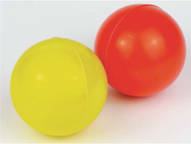
FIGURE 8-1 Example colored balls for targets; I’m using the yellow one on the left.
The Official Raspberry Pi Camera Module
To give your robot the ability to see, you will need a camera. In this project, we’ll be using the official Raspberry Pi Camera Module, shown in Figure 8-2.

FIGURE 8-2 The official Raspberry Pi Camera Module
The Camera Module is a Raspberry Pi add-on board designed and produced by the Raspberry Pi Foundation. The latest model features an 8-megapixel sensor and is less than 1 inch square in size! Not only does it take great still photos, but the Camera Module is also able to shoot full-HD 1080p video at 30 frames per second. If you have the older 5-megapixel model, don’t worry: it is fully compatible with this project and used in exactly the same way.
The 6-inch ribbon cable on the Camera Module attaches to the CSI (Camera Serial Interface) port on the Raspberry Pi, shown in Figure 8-3. It is compatible with all models, including the latest version of the Pi Zero.

FIGURE 8-3 The CSI interface port on the Raspberry Pi
NOTE
The Pi Zero has a mini-CSI connector rather than the full-size one found on all other Raspberry Pi models. To connect a Camera Module to the Zero, you’ll need to also purchase a mini-CSI-to-CSI cable. These are branded online as “Pi Zero Camera Cables” and cost around $5. Keep in mind that this project requires intense image processing and code that will run better on the faster full-size Raspberry Pi models than it will on the Zero or original Raspberry Pi models.
You can buy the official Raspberry Pi Camera Module online at the usual retailers. It costs approximately $30.
When looking online you may notice that there are actually two different official Camera Modules: the normal camera and the NoIR version, which can be used for night vision. You need the standard Camera Module. You can easily tell the two boards apart by their color difference: the circuit board of the normal Camera Module is green, whereas the NoIR is black.
CONNECTING AND SETTING UP YOUR CAMERA MODULE
Before you attach the Camera Module, ensure that your Pi is switched off. Then follow this process:
- Locate the CSI port on your Raspberry Pi. For all the full-size models of Raspberry Pi, this is found between the HDMI port and the 3.5 mm audio jack, and is helpfully labeled CAMERA.
- Next, open up the port by gently but firmly grabbing it from either side and pulling it upward (see Figure 8-4). This can be a delicate operation, and it often helps to get your fingernails underneath the sides.

FIGURE 8-4 The CSI port opened for cable insertion
- Insert the ribbon cable on your Camera Module all the way into the CSI port with the silver contacts facing away from the 3.5 mm audio jack and Ethernet port (see Figure 8-5). This orientation is critical: if you insert the Module’s cable the other way around, it won’t be connected properly and you will not be able to use it!
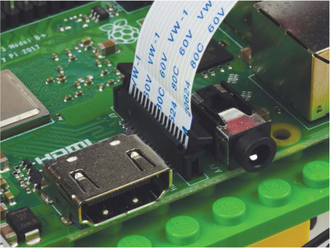
FIGURE 8-5 CSI port with the Camera Module’s ribbon cable inserted in the correct direction
- Then, while holding the ribbon cable in place, place a finger on both sides of the CSI port and push it back down at the same time. If both sides don’t close simultaneously, then one side will not close properly and the cable may come loose. Figure 8-6 shows a properly attached ribbon cable. Notice that a fraction of the silver contacts are just visible, and they’re all parallel with the board.

FIGURE 8-6 My correctly connected Camera Module ribbon cable
- Finally, to ensure that the Camera Module is connected properly, give the ribbon cable a gentle tug near the CSI port. It should stay rigidly in place. If the cable comes detached or slips, don’t worry—just remove it and repeat these steps.
If you want to connect the Camera Module to a Raspberry Pi Zero, the process is similar. Find the mini-CSI port on the right-hand side of the board and open it using a finger on either side of it. Then, make sure the silver contacts face downward toward the board when you insert the Pi Zero camera cable. See Figure 8-7.

FIGURE 8-7 The correct orientation of the camera cable for the mini-CSI port on Pi Zero models
Mounting Your Camera
Now that you have the camera connected to the Pi on your robot, you need to mount it in an appropriate position. I recommend using some sticky tack to affix it to the front of your robot, relatively low to ensure it will have a clear view. To do this, I’ve used a 2 × 2 LEGO brick to create some mounting space (see Figure 8-8). Also make sure that your camera is positioned the correct way up, like mine is in the picture.

FIGURE 8-8 My Camera Module mounted on my Raspberry Pi robot
The Camera Module is quite delicate, so handle it with caution. Try not to contort the cable too much and make sure to not leave any kinks in it. If at any point the ribbon cable comes loose from the Raspberry Pi, just reattach it the same way as before. If it comes loose from the connector on the actual module then you can also just reattach it. This is done in the same way: use your fingers to lever open the module’s CSI port and then insert the cable with the silver contacts facing down and toward the PCB.
Enabling the Camera and VNC, and Setting the Screen Resolution
To use the camera in Raspbian, you first need to enable it. If you followed all of the instructions in Chapter 1, you’ll already have done part of this. On top of that, we’ll need to enable VNC for this project and manually set up the right screen resolution. Here’s the full process.
To do this setup, we’ll use the configuration tool, raspi-config. Open the command line and enter the following:
pi@raspberrypi:~/robot $ sudo raspi-config
You should see the same blue configuration screen you met when configuring the audio output of your Raspberry Pi a few chapters ago. Using the arrow keys, scroll down to Interfacing Options and then press ENTER. This opens up a new menu shown in Figure 8-9.

FIGURE 8-9 The Interfacing Options menu of the raspi-config tool
Select Camera by pressing ENTER again. Then, when asked whether you’d like to enable the camera interface, use the left/right arrow keys to select Yes (see Figure 8-10).

FIGURE 8-10 Enabling the camera using raspi-config
You’ll see a message confirming that the camera interface has been enabled and then you’ll return to the original menu.
While you are in the raspi-config tool, it is also important to ensure that VNC is enabled. VNC will be fully explained in the next section, but for now just scroll down to Interfacing Options again, and then select VNC (see Figure 8-11). Press ENTER to enable it.

FIGURE 8-11 Selecting VNC from Interfacing Options
You’ll be sent back to the original menu. Before you can exit the configuration tool, you have to do one last thing: manually set the screen resolution of your Pi. This will ensure that when we use VNC later, the screen will be set up in the right way. To set the resolution, from the original menu, scroll down to Advanced Options, and then scroll down and select Resolution (see Figure 8-12).

FIGURE 8-12 The screen resolution option inside Advanced Options
NOTE
If you know that the resolution of your PC’s screen is lower than full HD, then set the screen resolution of your Pi to the closest lower option in the menu. You can always run raspi-config again to change the resolution at a later point.
You will then be prompted to choose a screen resolution. Use the arrow keys to scroll down to the full HD option. It will look something like “DMT Mode 82 1920x1080 60Hz 16:9.” Press ENTER on this option, and your screen resolution should now be set! You’ll be returned to the original menu.
Exit the configuration tool by pressing the right arrow key twice (highlighting Finish) and then pressing ENTER. Reboot your Raspberry Pi if prompted to do so.
TAKING A TEST PHOTO
With your Camera Module connected and enabled, let’s test it by taking a photo. This is easy to do from a remote terminal with a simple command, but by using that method you won’t be able to view the image it took in the text-based environment! This is where VNC, the option you enabled previously, comes in.
Controlling Your Pi’s Desktop Remotely with VNC
VNC stands for Virtual Network Computing. It allows you to remotely view and control your Raspberry Pi’s desktop from another computer, a little bit like what you’ve been doing with SSH, but for the full graphical user interface (GUI) rather than just the terminal. Since we can view the Pi’s GUI using VNC, you’ll easily be able to see any photos that you take with the Raspberry Pi Camera Module using Raspbian’s built-in image viewer.
NOTE
If you’ve been following along with this book and not using your Raspberry Pi wirelessly over SSH, don’t worry! You can still follow the steps after this section and view the results with your Pi connected to a monitor over HDMI.
Installing and Making a Connection with VNC Viewer
You have everything set up on the Raspberry Pi end, and now you need to download a VNC viewer on the computer you want to view the images on. We’ll use some free software called VNC Viewer from RealVNC, which is compatible with Windows, Mac, Linux, and more. To install the software, follow this process on your machine:
- On your computer, open a web browser and go to https://www.realvnc.com/en/connect/download/viewer/. You should see the download page for the VNC Viewer software, shown in Figure 8-13.
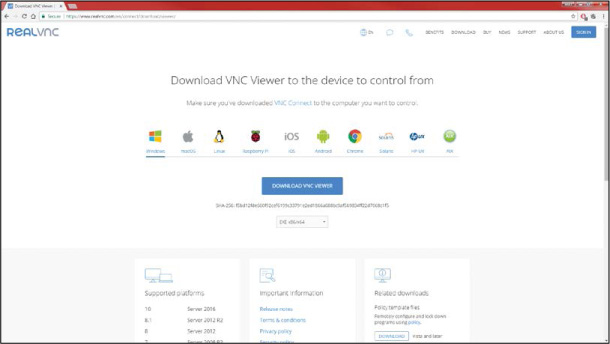
FIGURE 8-13 The VNC Viewer software download page
- From here, select your operating system and click the Download button. Once the software has downloaded, go through the installation wizard and agree to the terms of service. A few minutes later, everything should be installed and ready!
With VNC Viewer now installed, run it. You should see a window with a box at the top (Figure 8-14); here, you’ll enter the IP address of your Raspberry Pi, which you should already know since you’ve been using it to connect to your Pi over SSH.
An authentication box will appear asking you for a username and password. Enter the login details of your Raspberry Pi and click OK. If you haven’t changed the default user, then the username will be pi and the password will be whatever you set it to in Chapter 1.

FIGURE 8-14 Setting up VNC Viewer to connect to my Raspberry Pi
A new window will appear displaying your Pi’s desktop (see Figure 8-15). Here you can access and use everything just the same as if your Pi were plugged into an HDMI monitor.

FIGURE 8-15 A terminal and file manager in my Raspberry Pi desktop environment, viewed with VNC
Taking and Viewing a Photo Using the Raspberry Pi Camera Module
Now that you have everything set up, you can take your test photo! We’ll use a built-in command-line tool called raspistill. Open up a terminal, either through an SSH connection or by using a terminal window in the desktop environment over your VNC connection, and enter the following command to take a photo:
pi@raspberrypi:~ $ raspistill –o test.jpg
After a 5-second delay (to make sure you can get in front of your camera or frame your shot), this command will complete. If you see no output, that’s great news! There is no success message for this particular command. This instruction takes a picture and saves it as test.jpg in the directory where the command was run—in this case, the default home directory.
To view the image in the VNC desktop, click the File Manager icon in the VNC desktop environment (it looks like a collection of folders, as shown in Figure 8-16).
CAMERA TROUBLESHOOTING
If running the raspistill command gives you a scary error similar to the following, don’t worry!
pi@raspberrypi:~ $ raspistill -o test.jpg
mmal: mmal_vc_component_enable: failed to enable component:
ENOSPC
mmal: camera component couldn’t be enabled
mmal: main: Failed to create camera component
mmal: Failed to run camera app. Please check for firmware
updates
You most likely just haven’t connected your camera properly. If you get this error message, or any other, check the ribbon cable connections between the Camera Module and your Pi. Also ensure that you have enabled the camera interface properly—turn back to page 172 for guidance.

FIGURE 8-16 The File Manager icon
Navigate to the directory you ran the raspistill command from (I ran mine in the default home directory), locate test.jpg, and double-click it. You should see the photo that you just took in the Image Viewer (see Figure 8-17).


FIGURE 8-17 The test.jpg image in Raspbian’s Image Viewer over VNC (top); the test.jpg image, which features a stapler, Carl Sagan’s Cosmos, and two colored balls for use later (bottom)
MAKE YOUR ROBOT SEEK AND FOLLOW A BALL
Now you have your camera hooked up and a successful image test under your belt, it’s time to move on to the advanced project in this chapter: making your robot recognize and follow a colored ball. But first: a quick lesson in some important theory.
Understanding the Theory Behind Colored-Object Recognition
How do we get a robot incapable of independent thought as we know it to detect and identify a particular object?
As your robot moves around, the position of the ball relative to your robot will be constantly changing, so the first thing we need is a continually refreshing view of what is in front of your robot. The Camera Module provides this view through a stream of images, often referred to as video frames or just frames.
Each image, like the one in Figure 8-18, will need to be analyzed to identify whether or not it contains your colored ball. To do this, we will apply various image processing techniques.

FIGURE 8-18 An untouched image from the Camera Module, ready to be analyzed
The first step is to convert the image, which is in an RGB format, into an HSV format. We discussed RGB in Chapter 6, but I’ll briefly summarize here. RGB stands for red, green, and blue. Each pixel of the image from the Camera Module in Figure 8-18 is made out of a combination of these three colors, represented as three numbers between 0 and 255—for example, [100,200,150].
Computers use RGB for displaying colors, but for processing images and the color data they contain, the HSV color format is much more appropriate. HSV stands for hue, saturation, and value, and it is just another way of digitally representing color with three parameters. HSV is a bit more complicated to understand and represent than RGB, but it is often easiest to get your head around when viewed as a cylinder (see Figure 8-19).

FIGURE 8-19 An HSV cylinder
Hue is the color portion of the HSV model, and it is expressed as a number from 0 to 360 degrees. Different sections of this range represent the different colors (see Table 8-1).
TABLE 8-1 The Hue Ranges of HSV
COLOR |
ANGLE |
Red |
0–60 |
Yellow |
60–120 |
Green |
120–180 |
Cyan |
180–240 |
Blue |
240–300 |
Magenta |
300–360 |
Saturation is the level of white in a color, from 0 to 100%. Value works alongside saturation and can be thought of as brightness; it describes the intensity of the color from 0 to 100%.
By converting each image into an HSV format, your Pi is able to separate just the color component (hue) for further analysis. This means that the computer should still be able to recognize a colored object, regardless of the environment and its lighting effects. This would be incredibly difficult to achieve in an RGB color space. Figure 8-20 shows an RGB implementation of the HSV data.

FIGURE 8-20 HSV data of the image
As you can see in Figure 8-20, the yellow ball my robot will follow is now clear and distinctive. There is no possible way that it could be confused with the red ball behind it, or any of the other objects in the frame. Remember, though, that this is an RGB implementation of HSV color. The hue value of a color is not something that we can see in the same way with our own eyes.
The next stage in the process is to look for and identify any color that matches the one we are searching for. In my case, I want to match all the parts of the image that are the same color as my yellow ball. This forms a mask (see Figure 8-21) that simply keeps the parts of the image we want and removes the parts we don’t want. You can see that it keeps only the areas that contain my desired color, yellow.

FIGURE 8-21 Masking out the colors and areas of the image that are not the same shade of yellow as the ball. Notice that there are areas on the ball (bright reflections/shadowy regions) that aren’t picked up!
Now that the relevant colored objects have been isolated, the next step in the process is to identify the largest patch of color. Notice how there are other (albeit small) readings of yellow in Figure 8-21? If you don’t program this right, your robot might get confused and head toward those instead of the desired ball. This could be disastrous—after all, you don’t want it to get distracted by distant bananas!
Assuming that the largest part of the mask is the colored ball, the next stage is to actually find that largest area. We do so by drawing a contour (like an outline; see Figure 8-22) around each detected object in the mask. We can work out the area of each contour using some basic mathematics. The largest area is then identified and assumed to be our target ball!

FIGURE 8-22 Contour drawn around the largest single object in the mask
After this, we simply need to program the robot to move toward the object. If the target is to the right of the robot, move right. If it is to the left of the robot, move left. If it is in front of the robot, move forward.
And that’s all there is to making a ball-following computer vision system with your Raspberry Pi! It’s time to put it into practice.
Installing the Software
You’ll need a couple of Python libraries to enable computer vision. Most notably, we will be using OpenCV, a free and open source library of programming functions for real-time computer vision. You will also need the PiCamera Python library to manipulate and handle the Camera Module in Python, though this is included by default in the latest versions of Raspbian.
To install the dependencies for the OpenCV Python 3 library, enter the following command into the terminal:
pi@raspberrypi:~ $ sudo apt-get install libblas-dev
libatlas-base-dev libjasper-dev libqtgui4 libqt4-test
NOTE
If you get any errors during this installation process, or it just doesn’t look like it has gone correctly, visit the book’s website at https://nostarch.com/raspirobots to check for any changes and get further guidance.
When prompted as to whether you want to continue, press Y and then ENTER. This command will take a few minutes to execute.
Now, you can use pip (the Python software management tool we have used previously) to install OpenCV for Python 3. Enter the following command:
pi@raspberrypi:~ $ sudo pip3 install opencv-python
After the OpenCV installation has finished, check that you have the PiCamera library installed with the following command. It will most likely inform you that you already have the newest version, but if not, proceed with the installation:
pi@raspberrypi:~ $ sudo apt-get install python3-picamera
And that’s all you will need!
Identifying the HSV Color of Your Colored Ball
To identify a ball of a specific color, your Raspberry Pi robot needs the HSV value of that color. The Pi will use this value to compare each part of each image to see whether it is the color of the ball that you want your robot to follow.
Your ball is probably a different color than mine, so you’ll need to find out the exact HSV value for yours. Even if you have a yellow ball as I do, it may be a slightly different shade from mine!
There are various ways to identify the hue value you’ll need, but I’ve found that the best method is to try out various values on your Raspberry Pi and observe the effects. The aim is to find the one that matches your particular colored ball. To help you do this, I have created a test program, hsv_tester.py, which you can find in the software bundled with this book (https://nostarch.com/raspirobots/). The next section will walk you through running the program.
Running the HSV Test Program
Place your robot in a well-lit environment, with your colored ball approximately a meter in front of it. Then boot up the Pi on your robot and view its desktop remotely over VNC. Next, open up a terminal application in the desktop, locate the hsv_tester.py program, and run it using the command:
NOTE
I won’t go into the specifics of how this tester program works, because it’s very similar to the actual ball-following code that you will use in a few pages. I’ll follow that code up with the usual detailed explanation.
pi@raspberrypi:~/robot $ python3 hsv_tester.py
You’ll see a prompt asking you for a hue value between 10 and 245. Try approximating the hue value of your ball; the ranges in Table 8-1 should give you a rough idea of what end of the spectrum to start at. Mine is yellow, so I’m going to guess 40. When you enter the value, you’ll see four new windows appear, showing you the different stages of image processing discussed previously (see Figure 8-23).

FIGURE 8-23 The four different windows of the HSV tester program
The first window, titled Camera Output, is a raw RGB video output directly from the Camera Module ➊. The second window, titled HSV, is the same video converted into HSV format ➋. Then, the window titled Color Mask displays the parts of the image that match the hue number you provided ➌. Finally, the window titled Final Result overlays the color mask with the original video feed, showing you the isolated area ➍.
If the mask in the Final Result window is more or less ball-shaped, you have your hue!
It is unlikely that you’ll get your hue value correct the first time, just as I haven’t—the hue didn’t match my ball but instead it got parts of the stapler in the frame! To try again, select any of the output windows (but not the terminal window), and press Q on your keyboard. This will freeze the video output, and you can then go back to the terminal and enter another value to try.
Play around and tweak the hue until you get a definitive match for your colored ball. After a little while, I found that my magic number was 28. When you have found yours, you should see that the majority of your ball and not much else is left in the frame, like mine in Figure 8-24.

FIGURE 8-24 My output windows after I correctly identified my hue number as around 28
Make a note of the value, as you’ll need it soon. After you’ve found the right number, close the HSV tester program by pressing CTRL-C in the terminal window.
Programming Your Raspberry Pi to Follow a Ball
With all of the groundwork in place, you can now program your Raspberry Pi robot to follow a ball! The program we’ll be using is relatively long and more advanced than anything you’ve met so far, so I recommend downloading it from the software bundle rather than copying it from this book to minimize typos. The program is called ball_follower.py and you can check it out with the command:
pi@raspberrypi:~/robot $ nano ball_follower.py
This program is 75 lines long, so for the explanation I’ve split it into sections and will explain how each part works. If you’re more interested in just running the code first and understanding how it works later, skip ahead to the next section on page 193.
Importing Packages and Setting Up the Camera Module
First we’ll import the packages we need and set a few things up, as shown in Listing 8-1.
➊ from picamera.array import PiRGBArray
from picamera import PiCamera
import cv2
import numpy as np
import gpiozero
➋ camera = PiCamera()
➌ image_width = 640
image_height = 480
➍ camera.resolution = (image_width, image_height)
camera.framerate = 32
rawCapture = PiRGBArray(camera, size=(image_width, image_height))
➎ center_image_x = image_width / 2
center_image_y = image_height / 2
➏ minimum_area = 250
maximum_area = 100000
LISTING 8-1 Importing libraries and setting up the Camera Module
The first lines of the program ➊ import the necessary libraries, including various parts of the PiCamera library needed to allow us to use the Camera Module in Python. We also import the OpenCV library, cv2; gpiozero as usual; and the NumPy library, np. NumPy is a Python package used for scientific computing and will be useful for manipulating the image data later.
At ➋, we initiate a PiCamera object and assign it to the camera variable for use throughout the program. Next we define the size ➌ and resolution ➍ of the images being fed from the camera. We won’t need full-HD video frames and they would just slow down speed and performance, so we downgrade the resolution to standard definition: 640×480 pixels. On the lines following this, we specify the frame rate of the camera and the raw capture setup.
The two lines at ➎ work out where the center of the image is. This information will be used later to determine and compare where the ball is in the frame.
Then at ➏, we set a minimum and maximum area for the colored ball. This prevents your robot from detecting and following any colored object smaller than 250 square pixels or larger than 100,000 square pixels. These are arbitrary numbers that I’ve found work pretty well, but if you want to change them later, feel free!
Setting Up the Robot and Color Values
This section deals with the final part of the setup process, shown in Listing 8-2.
robot = gpiozero.Robot(left=(17,18), right=(27,22))
➊ forward_speed = 0.3
turn_speed = 0.2
➋ HUE_VAL = 28
➌ lower_color = np.array([HUE_VAL-10,100,100])
upper_color = np.array([HUE_VAL+10,255,255])
LISTING 8-2 Setting up the robot and color values
We set up the robot and its motor pins as before and then define two variables for both the forward and turning speeds ➊, with the values 0.3 and 0.2, respectively. This will limit the speed of your robot when it moves toward your colored ball. Again, these are arbitrary numbers, so you can change them if you find that higher or lower values work better for you and your robot.
At ➋, we set the number for the hue. This is a value you must change to the value you found earlier using the HSV tester program. I have set mine to 28.
Next we set a range of values for the robot to check for instead of a precise one ➌. That way, changes in the environment, like the room’s lighting and how bright it is, will still fall within this small range and therefore the ball will continue to be detected. We do this by using arrays to create the upper and lower bounds of the color in HSV format.
In programming, an array is a collection of information where each piece of data in the array has an index, or location, associated with it. Arrays can be as long as you like and can store anything you want, from people’s names to types of animal to lists of numbers. In Python, the first piece of data in an array has an index of 0, the second piece has an index of 1, the third piece has an index of 2, and so on—in other words, Python starts counting the items in an array at 0. This means that, in a Python program, you could ask for the piece of information stored in the array at index 3, for example, and it would return the data found in the fourth position.
In this situation, we use arrays to represent the HSV format, as each HSV color can be described with three numbers (the hue, saturation, and value). Notice that we actually search for hues ±10 in either direction, and that the range for the saturation and value components of the color goes from 100 to 255. This ensures that the robot will look for a broader range of colors in each frame from the camera and improves the odds that it will detect the target colored ball.
These arrays are available to use through the NumPy library we imported. We use NumPy here because it is a highly optimized library for fast array calculations. This gives us the speed necessary to access and analyze each pixel of each frame.
Analyzing the Camera Frames
The third section of the program is shown in Listing 8-3. This is where the bulk of the code and computer vision process starts.
➊ for frame in camera.capture_continuous(rawCapture, format="bgr", ![]()
use_video_port=True):
➋ image = frame.array
➌ hsv = cv2.cvtColor(image, cv2.COLOR_BGR2HSV)
➍ color_mask = cv2.inRange(hsv, lower_color, upper_color)
➎ image2, countours, hierarchy = cv2.findContours(color_mask,
cv2.RETR_LIST, cv2.CHAIN_APPROX_SIMPLE)
LISTING 8-3 Starting capture for loop, converting image, and finding contours
At ➊, we initiate a for loop that, translated into plain English, reads: “for each frame from the Camera Module, do this.”
Next, the information from the current frame is saved to the variable image as an array ➋. The RGB data of image is then converted into an HSV format ➌ using an OpenCV function, cvtColor().
Once the HSV data has been acquired, the color mask, which keeps only your desired color, is created ➍. We use OpenCV’s inRange() function so that the mask keeps all of the colors that fall between the lower and upper bounds of your color choice.
The next stage of the process is to draw lines around each distinct object in the mask so that the area of each detected object can be compared later. We do this at ➎, using OpenCV’s findContours() function.
Comparing Contours to Find Your Ball
Next up is Listing 8-4, which compares each contour and identifies the largest one.
➊ object_area = 0
object_x = 0
object_y = 0
➋ for contour in contours:
➌ x, y, width, height = cv2.boundingRect(contour)
➍ found_area = width * height
➎ center_x = x + (width / 2)
center_y = y + (height / 2)
➏ if object_area < found_area:
object_area = found_area
object_x = center_x
object_y = center_y
➐ if object_area > 0:
ball_location = [object_area, object_x, object_y]
➑ else:
ball_location = None
LISTING 8-4 Comparing and finding the largest contour
We create three variables ➊ that will later be used to store the largest object’s area and center coordinates. Initially we set these to zero.
At ➋ we start a for loop that will loop through each and every detected contour. The code at ➌ will draw a rectangular box around a contour to approximate its shape. This is known as a bounding box, and it just makes the objects easier to work with. We assign the details of this bounding box to four new variables: x, y, width, and height. As you’d expect, width and height represent the width and height of the rectangle; x and y represent the x- and y-coordinates of the top left of the box.
Next, we calculate and store the area of the current contour using the formula for the area of a rectangle: width × height ➍. Then we figure out the center coordinates of the current contour ➎ to let the program know where in the frame this particular object is located. Knowing the coordinates of the center of the object is far more useful than knowing where its top-left corner is.
At ➏ we compare the current contour’s area with the previous largest area already found. If the current contour is larger than the previous one, we assume that the larger area is most likely your colored ball. Consequently, the previous contour’s information is discarded, and the details of the new contour are overwritten on the three variables used to store the largest object’s area and center coordinates.
Once the for loop ➋ has finished, and all of the contours have been compared, the program verifies that a suitable contour has been found and uses an if statement ➐ to check whether the area of the contour is larger than 0. If it is, the largest contour, and therefore probably the ball, has been found and its exact details are saved in a list (a type of basic array) to a variable called ball_location. If a contour hasn’t been found, the variable ball_location is set to None in the else clause ➑.
Making Your Robot React to the Ball
The last part of the program, found in Listing 8-5, deals with making your robot move depending on where the colored ball has been detected in the frame.
➊ if ball_location:
➋ if (ball_location[0] > minimum_area) and (ball_location[0] ![]()
< maximum_area):
➌ if ball_location[1] > (center_image_x + ![]()
(image_width/3)):
robot.right(turn_speed)
print("Turning right")
➍ elif ball_location[1] < (center_image_x - ![]()
(image_width/3)):
robot.left(turn_speed)
print("Turning left")
➎ else:
robot.forward(forward_speed)
print("Forward")
➏ elif (ball_location[0] < minimum_area):
robot.left(turn_speed)
print("Target isn't large enough, searching")
➐ else:
robot.stop()
print("Target large enough, stopping")
➑ else:
robot.left(turn_speed)
print("Target not found, searching")
rawCapture.truncate(0)
LISTING 8-5 Making the robot move depending on where the ball is found
This part of the code features a lot of if, elif, and else statements and jumps around, so go through it carefully and pay attention to the indentation to understand how each statement is constructed.
We declare a simple if statement ➊ that translates to “if there was a ball found, do this.” If there is no ball found, the program skips right down to the else statement ➑. The program then tells the user that a suitable target wasn’t found and commands your robot to turn left in order to search for the ball in the surrounding environment.
If a ball was found in the current frame, an if statement ➋ detects whether the size of the ball (stored in the ball_location list at index 0) is within the area values you defined at the start of the program. If the object detected is too small, the robot starts to turn to see if it can find a larger target ➏. If the object detected is too large (caught by the else statement ➐), the robot moves no closer to the ball and stops.
If the ball is in frame and the robot does need to move, the code through ➏ handles this. At ➌ we use an if statement to detect whether the x-coordinate of the ball in the frame is greater than the center point plus a third of the image width. If this is the case, the ball must be in the right-hand side of the frame and consequently the robot moves right.
The code at ➍ does the same thing but sees whether the x-coordinate of the ball in the frame is less than the center point plus a third of the image width. In this case, the robot turns left.
Finally, if the ball is not in either the left or right of the image, it must be in front of your robot and therefore the robot is instructed to move forward ➎.
As you can see in Figure 8-25, the camera frame is essentially being split into three different areas by this code: left, right, and forward. We use a third of the whole frame’s width on either side of the center point to be the middle section. This means that the middle section represents two-thirds of each frame. If the ball is found here, the robot moves forward. If it’s found on either side, the robot moves left or right. The left and right sections are a sixth of each frame, respectively.
And that’s all there is to the ball-following program! The code may have appeared complicated at first, but as with most things in computer science, if you break it down and look at it carefully, you’ll find it is made out of the same simple concepts you’ve used before.

FIGURE 8-25 A diagram of how the frames are split into three areas for movement
Running Your Program: Make Your Robot Follow a Colored Ball!
Now you can get to the exciting part of this project: actually making your robot follow your colored ball. Power your robot with its batteries and place it on the floor or another large flat surface. Also place your colored ball somewhere in this environment, as shown in Figure 8-26.

FIGURE 8-26 My robot, ready to hunt my yellow ball!
When you have everything set up, run the program with this command:
pi@raspberrypi:~/robot $ python3 ball_follower.py
Your robot should spring to life and start hunting down your colored ball. Play a game of fetch with your new smart pet!
As usual, press CTRL-C to stop this program.
EXPERIMENTING WITH IMAGE PROCESSING
As with the line-following project in the previous chapter, computer vision and image processing are areas of computer science and robotics that lend themselves to fine-tuning in order to improve results and capabilities. Here are some suggestions for you to play around with.
Color and Object
While your colored ball is a great starting target for your robot, you can easily take it even further. For example, why not introduce a second color by scanning each frame for a secondary set of HSV values? Make your robot follow both yellow and red objects, for example. Remember that you can go back to the HSV tester program to work out the hue and color codes of other shades!
You’re also not just restricted to balls. You can make your robot follow or seek anything that is primarily a single color. Experiment with other objects that you have lying around!
Speed
How fast your robot moves does have a big effect on the quality of its image processing: usually, the faster it goes, the more likely it is to miss your colored object. That said, feel free to play around with the speed values defined at the start of the ball-following program—you may be able to fine-tune and improve your robot’s performance!
Minimum/Maximum Area of Object
Experiment with the minimum and maximum area of the target object. Remember that your robot by default will not move toward anything smaller than 250 square pixels, and it will stop at anything larger than 100,000 square pixels.
By changing these numbers, you can make your robot move toward targets that are potentially smaller or even stop closer to the target. A fun idea is to increase the maximum area to a point where your robot won’t stop when it gets close to your colored ball. The result is that your robot usually ends up bumping into the ball and “kicking” it . . . only to trundle after it again and repeat the process!
Remember that each frame of the video feed from your Camera Module measures 640×480 pixels, so a value of 307,200 is the maximum number of square pixels possible.
Avoidance Behavior
At the moment, your robot loves your colored ball, but what if you made it so the opposite was true? Try editing the program so that your robot runs away from the object, rather than toward it.
An extension of this would be to make your robot move toward certain colored balls, but run away from others. For example, it could love red balls but be terrified of yellow ones!
SUMMARY
In this chapter, you’ve given your robot the advanced ability to seek out, recognize, and follow a colored ball. You have learned the basics of image processing and implemented an entire computer vision process in Python using the official Raspberry Pi Camera Module.
And with that you have completed the projects section of this book! Your little robot is now all grown up, and you’re its proud parent. This isn’t the end of the line though; check out “Next Steps” on page 195 for some guidance and suggestions for continuing your adventures in robotics, programming, and Raspberry Pi.