Chapter 9. PKI in Unified Communications
This chapter is dedicated to integrating PKI concepts into your Unified Communication infrastructure.
That is one important step in securing UC through the following:
• Authentication and encryption of calls
• Integration in your Network Admission Control (802.1x) solution
The Cisco Unified Communications infrastructure (mainly IP Phones and voice gateways) can benefit from integration into your PKI.
This chapter starts by setting the foundations of PKI implementation in Cisco UC solutions. Then you see how devices can be provisioned with certificates to build trusted chains. Finally, you review typical applications in which the availability of certificates can bring some interesting benefits: voice calls security, ASA Firewall TLS Proxy feature, and IP Phones 802.1x authentication.
PKI Concepts in Cisco UC
Although the main PKI foundations are still present in Cisco UC implementations, a few specific concepts have been developed or added, mainly with the aim to ease use and deployment.
You need to understand a few functions and acronyms that will be used later in this chapter because they will be integrated later on in the reviewed application examples.
Manufacturer Installed Certificate (MIC)
Every IP Phone (from the latest generations of products) has a public and private key pair, and a dedicated certificate installed when leaving the factory. That certificate, known as a Manufacturer Installed Certificate (MIC), is issued by a common Cisco Manufacturing CA, which is a subordinate of the Cisco Root CA.
The Common Name (CN) in those certificates is created from the phone model and its MAC address; for example, CN=CP-7961G-GE-SEP00ABXXXXXXXX.
That’s good because it means that each IP Phone can immediately participate into PKI processes. However, because all phone certificates have the same issuer (Cisco Manufacturing CA), any Cisco IP Phone (including the ones bought by your neighbor) will authenticate successfully. It is therefore required to also perform authorization based on the CN to get more granular control.
Another aspect is the lifetime of the certificates: MICs are valid for 10 years from the manufacturing date. Although ten years is already significant for the lifetime of IT equipment, some setups definitely survive longer. As MIC’s cannot be renewed, relying solely on them can become a long term blocking point.
Local Certificates
To overcome those limitations, you need to use a local and more controlled PKI.
A Locally Significant Certificate (LSC) is one that you create (you see later how to do this) and is installed on the IP Phone. It is stored in parallel with the MIC and will not replace it. When an LSC is installed, it takes precedence over the MIC.
The Certificate Authority Proxy Function (CAPF) is the software entity, residing on the CUCM server, responsible for creation, distribution, and maintenance of the LSCs. The CAPF can be autonomous, with a self-signed certificate or be integrated into an existing (companywide, for example) PKI. Each Cisco Unified Communications Manager (CUCM) server will have its own certificate, by default self-signed or issued from an external certificate authority. There is no concept of MIC for CUCM servers.
Creating Trust
From the preceding, you can understand that you can end up with multiple disconnected PKI topologies, without any trust relationship in between. These topologies include the following:
• MIC certificates, based on Cisco CA
• Self-signed certificates for each components (CUCM servers, TFTP servers, and so on)
• CAPF certificate and LSCs for phones
How do you get the different components to work together in a secure manner? The solution is to use a secure list of trusted certificates, known as Certificates Trusted List (CTL) file.
Such a list is created using a digital envelope in which all trusted certificates (and associated public keys) are packaged. The envelope is then signed by an administrator using a USB security token. The token is provided by Cisco and contains a key pair (protected by password) and a certificate issued by Cisco Manufacturing CA, which is trusted in the default factory configuration of IP Phones.
For security and redundancy reasons, it is required to sign the CTL file using two administrator tokens, which are stored in the file. After a CTL file has been downloaded by the phones, it can only be replaced by a new CTL file signed by one of the tokens present in the current CTL file. That mechanism prevents the distribution of rogue CTL files after the initial CTL file has been distributed.
A dedicated software tool, CTL Client, can create and manipulate CTL files. After they have been signed, they are published on a TFTP server for retrieval by the IP Phones.
The first CTL download (when there is not yet any CTL installed on the phone) must be considered insecure because it cannot be verified (any Cisco token signature is valid) and should therefore be performed over a secure network connection. The same applies when phones are reset to factory defaults and need to reload a new CTL file.
As represented in Figure 9-1, a typical CTL file would contain certificates for the following components (one or more of each).
Figure 9-1 CTL File Generation with CTL Client Software

• CAPF
• TFTP
• Admin Token 1 and 2
You can find more information on the CTL Client in the CUCM Security guide: http://www.cisco.com/en/US/docs/voice_ip_comm/cucm/security/8_0_2/secugd/secuauth.html.
Certificates Distribution
This section focuses on the process used to enroll IP Phones into a local PKI, meaning that they will each have an LSC installed as result. As a reminder, all IP Phones already have a MIC installed from the factory, which might be sufficient for your needs.
Getting certificates installed (either self-signed or enrolled) on the various other UC components (CUCM, TFTP, and so on) is straightforward but specific to the software version in use; consult the product documentation for that step.
CAPF
As previously mentioned, CAPF is responsible for signing and distributing LSC to IP Phones. Let’s look deeper into that process. The CAPF can be a CA, using its self-signed certificate to issue certificates to the phones. That is the simplest and default configuration for LSC.
The same CAPF is used when the phone certificate must be upgraded (renewal close to the expiration date, change in attributes, and so on). CAPF is also used to retrieve an installed LSC from the phone, for example for viewing or troubleshooting. You can also delete LSC so that the default MIC is used again.
After installation, CAPF can retrieve the information about the registered phones from the CUCM database and display an authentication string unique for each phone.
Note
The previous steps to install CAPF require user interaction; to find CAPF documentation and detailed instructions, go to http://www.cisco.com/en/US/docs/voice_ip_comm/cucmbe/security/8_0_2/secugd/secucapf.html.
CAPF is the central location for all certificate-related operations and configuration, including the key size to use on the phones.
Phone Enrollment
Before working at the phone level, you must ensure that the backend infrastructure is ready. The following conditions must be met:
• CAPF certificate must be installed on the Call Manager server.
• CTL file must be created and contain the CAPF certificate and be published on a TFTP server.
Several authentication mechanisms are available for authenticating and enrolling phones on a CAPF server: authentication string, existing LSC, existing MIC or null string (no authentication). An authentication string requires manual user input on the phone, whereas others can be used in fully automated processes.
After triggering (manually or automatically) the phone to initiate a connection (secured through TLS) to the CAPF server, authentication can take place according to the server configuration, and the phone certificate will be installed, upgraded, or deleted through the secure channel.
Applications
After PKI is deployed to the various UC components, several applications or services can make use of it. The next section reviews some of the most common ones.
Call Authentication and Encryption
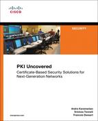
Because you have strong identity material in place (that is, digital certificates), you can now create secure communication channels between the phones and the various CUCM servers. One main application is call authentication.
In that process, as shown in Figure 9-2, both phone and server go through a challenge-response exchange, where the respective private keys are used to sign the responses, and public keys are used to validate them.
Figure 9-2 Mutual Authentication Between Phone and CUCM Server
Indeed, the phone has the CTL file that contains the server certificate (and therefore its public key). In the opposite direction, the phone sends its certificate to the server.
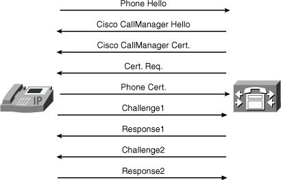
After authentication is successful, both entities have the option (configurable) to proceed to a session key exchange mechanism to create a secure communication channel for call signaling. To maintain consistency, it is not possible to use signaling encryption without prior authentication.
When encrypted signaling is used, you can go one step further and use media authentication and encryption, which can actually secure the voice or video streams. Secure Real Time Protocol (SRTP) is used for that purpose. The CUCM server is responsible for creating session keys for media security, and those keys are transmitted to the endpoints over the signaling channel; this is why secure signaling is mandatory. Figure 9-3 illustrates secure streams between endpoints.
Figure 9-3 Secure Streams Between Endpoints
Software and Configuration Security
Because the phones are controlled entirely remotely, including the download of software images and configuration files, you need to guarantee the security of operations.
Firmware images files (typically named image.bin.sgn) are signed using a Cisco CA certificate, which is also installed on the phone (as explained in the MIC section) and can therefore be used to validate that the image has not been modified.
For the phone configuration file, you need to use both encryption so that only the target phone can read it, and authentication so that it cannot be modified in transit.
The full set of crypto functions come into play, as depicted in Figure 9-4.
Figure 9-4 Securing Phone Configuration Files

On the server side:
• The public key of the target phone (either MIC or LSC, available via CAPF) is used by CUCM to encrypt the configuration.
• The private key of the TFTP server is used to sign the configuration.
• The TFTP server public key (available in CTL file) is used to verify the signature.
• The phone private key (available locally by definition) is used to decrypt the configuration.
802.1x and Network Admission Control
In the previous application, the PKI was used to secure the various communication flows between UC components (phones, CUCM servers, and TFTP servers). You can further extend the security, earlier in the process, by increasing the control over the phones trying to connect to the network. Indeed, as part of the global Network Admission Control (NAC) solutions, Cisco IP Phones have an embedded 802.1x supplicant, giving them the capability to authenticate toward the infrastructure (that is, the switch they are plugged into) using EAP-based protocols. Figure 9-5 illustrates 802.1x authentication of IP Phones.
Figure 9-5 IP Phone 802.1x Authentication

In the early days, IP Phones were detected on a switchport using specific Cisco Discovery Protocol (CDP) packets, bypassing NAC for those phones. Obviously that was not secure because those packets could easily be forged and spoofed by a malicious user wanting to gain access to the network. Then came the first phone-embedded supplicant, which supports the following authentication mechanisms:
• EAP-MD5, which relies on a password to perform challenge-based authentication.
• EAP-TLS or EAP-FAST, which use the certificates installed on the phone, either MIC or LSC, via TLS authentication protocols.
Note
It is beyond the scope of this book to review the complete NAC-related infrastructure configuration; refer to Cisco Network Admission Control, Volumes I and II for additional details about NAC architectures.
For PKI-related configuration issues, most changes must be applied to the backend authentication server (namely Cisco ACS RADIUS server). For EAP-MD5 (password) authentication, each phone must have a corresponding user entry in an ACS database, with a username based on the phone model and MAC address and the associated password configured. That same password must then be manually entered on each phone.
For EAP-TLS or EAP-FAST, if only authentication is required, there is no need to configure the individual phones on ACS: Adding the issuer CA (Cisco Manufacturing and Root CAs, local CA, or self-signed CAPF certificate) to the ACS trust list is enough to verify the credentials of the phones.
Note
CN authorization must be used in ACS 4.2 and below.
However, if authorization is required, phones must be entered in an ACS database, with the certificate CN field as username.
Note
CN field content is different in MIC and LSC certificates: MIC CN=CP-<MODEL>-SEPxxxxxx whereas LSC CN=SEPxxxxxx.
Because there is no out-of-the-box integration between CUCM and ACS, you can use CSV files to perform a bulk import of all registered phones into ACS. This is required only if you need to use authorization on ACS. In ACS version 4.x, bulk import is done via CLI, whereas it is a web-based operation in ACS 5.x. Refer to the corresponding ACS User Guide, available on Cisco.com.
Furthermore, the 802.1x phone supplicant can be enabled remotely through the phone configuration on CUCM, making such deployment much easier. There is no mutual TLS authentication: The phone is authenticated toward the ACS, but the ACS server is not authenticated toward the phones.
This is applicable for both wired and wireless IP Phones; however, wireless models are enrolled using a different process: Via the embedded HTTP GUI, a Certificate Signing Request (CSR) must be generated and transmitted to the CA, which then return a certificate to the phone. The wireless phone also needs to be loaded with the CA certificate or the ACS certificate to perform a mutual authentication. This is similar to the process used to enroll Cisco IOS devices and enables the wireless phone to securely authenticate and encrypt the radio communication.
ASA TLS Phone Proxy
Voice communications usually rely on a dual connection:
• One control channel transmits various states and parameters of the call.
• At least one media channel (often two) is responsible for carrying the actual voice data.
Although the control session uses well-known TCP or UDP ports, based on the protocol in use (SIP, SCCP, H.323, and so on) the data sessions typically use dynamic port numbers, often negotiated between the endpoints through the control channel.
Firewall devices have been made smart enough to inspect the control session and detect the dynamic ports that must be open to enable the secondary channels to flow through.
Earlier in this chapter, you saw how to use some security mechanisms to encrypt the sessions (both control and data), making blind all devices on the network path, including the firewalls. The only workaround is to open a wide range of ports to ensure that the media streams will not be blocked. Obviously that can pose a security risk, which is not acceptable in a large number of situations.
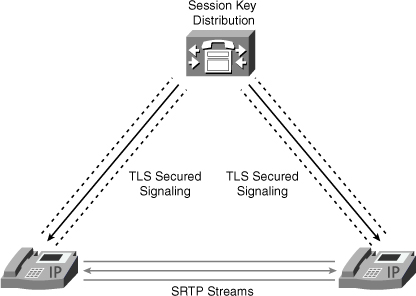
To avoid such weaknesses while still using encryption for UC traffic, the Cisco ASA 5500 security appliance has been enhanced with the TLS proxy licensed feature. As shown in Figure 9-6, the ASA Firewall will now act as a termination point for TLS sessions protecting the control channels of UC calls.
The firewall can then decrypt signaling packets, inspect the content to identify dynamic ports that must be opened for the SRTP media streams, and then encrypt again the signaling into another TLS session toward the other UC device (typically the Call Manager).
How do you build the trust relationship between the three components?
Phone—ASA TLS Proxy
The phone can trust any certificate present in the CTL file; therefore, the ASA certificate (self-signed or from another CA) must be added into the CTL. The ASA has the CAPF CA (or other applicable CA) certificate installed and can therefore verify the authenticity of the certificate presented by the phone.
ASA TLS Proxy—CUCM Server
The ASA must have the CUCM certificate installed as trusted. For the CUCM server to authenticate the ASA TLS Proxy, it is a little more complex. The ASA can generate on-the-fly a dynamic certificate containing the identity of the phone (named Local Dynamic Certificate, or LDC), signed with the ASA certificate, and present it on behalf of the phone. The CUCM server has the ASA certificate in its trusted list and can accept those dynamic certificates because they have a signature that can be verified as valid.
Note
The ASA certificates used in each step can be different; the ASA would then have the following:
• An “outside” certificate, used to communicate with the phones, and present in the CTL file.
• An “inside” certificate or signer certificate, used to sign LDCs and communicate with CUCM server. That certificate is installed in the CUCM trusted list.
Summary
This chapter showed how you can apply PKI to Unified Communications infrastructures.
Although some specific terminology and concepts are used (MIC, LSC, CTL, and CAPF) the basic crypto principles are applicable. The behavior should therefore be perfectly understandable after the language is acquired.
You reviewed the most common applications: from secure calls toward the ASA TLS Proxy feature that enables new extranet possibilities. You learned how Cisco IP Phones can participate in your deployed NAC solutions through the embedded 802.1x supplicant.