
Chapter 4. Troubleshooting
This chapter focuses on the steps you can use to troubleshoot a PKI-related problem. The intent is not to provide an exhaustive list of possible issues, but rather to teach you how to approach the problem and narrow down the possible failure cause. In some instances, assistance from Cisco TAC is ultimately be required, but by identifying failure points as precisely as possible, you might resolve issues without assistance.
This chapter is divided into three sections that map the lifetime of the certificate:
• Certificate Use and Validation
The examples are given for Cisco IOS-based devices but are applicable to other components such as Cisco ASA Firewalls.
Keying Material Generation
Although the key generation process on the device is straightforward and should not cause any problems, you need to pay attention to several parameters or options that must be selected at generation time and cannot be changed later; such changes would require the operator to perform the entire enrollment process again.
Key Sizes
Key size defines the level of security attached to the key. A larger key size is always more secure; the drawback, however, is that it requires more computing resources not only at generation time, but also for every operation (signature generation, verification, and so on) involving the key. In a large scale deployment with hub-and-spoke topology, for example, the load on the hub can potentially increase significantly when larger keys are used.
The key size ranges from 360 bits to 4096 bits, depending on the platform. The size to use might be dictated by your security policy. Currently, a minimum of 1024 bits for normal operations and 2048 bits for increased security (for example, the certificate server) is recommended. Because 4096 bits is not supported on all platforms, carefully evaluate the complete solution before adopting such settings.
Label
The label is a name that you give to the key pair. This is only locally significant because it is stored only on the device and will never be used as part of any PKI process.
By default, the label is the FQDN (hostname.domain-name) of the device.
In latest Cisco IOS releases, the keys will be renamed if you change the device name after the keys have been generated, as shown in Example 4-1.
Example 4-1 Automatic Update of Key Label

Note
For the last console output, although only one key pair was manually generated through the CLI, an additional key pair with a name ending with .server has been automatically created. This key is a temporary key, regenerated every hour, used by SSHv1 server as an additional security measure, completing the host key that is permanent and enabling the authentication of the server by the client. If only SSHv2 is enabled, the server key will exist but will not be refreshed hourly.
The label becomes important when the device has multiple key pairs simultaneously; for example, if it must be enrolled to more than one certification authority, you might want to use a different key pair for security reasons. (Although this is not mandatory.) In that case, it is a good practice to specify a meaningful label for each key pair created (or imported). The label can be referenced later in the trustpoint configuration section.
Exportable Keys
An exportable key pair means that you can take a copy of both private and public keys. This is mostly useful for backup purposes. By default, private keys are not exportable as this is the most secure option. If you choose to mark the keys “exportable,” be aware that the private key can now be duplicated for both good and bad intents. Access to the original device must therefore be secured accordingly. The exportable flag can be set only at generation time. In latest Cisco IOS releases, the flag can be later changed from exportable to non-exportable, as shown in Example 4-2, but not from non-exportable to exportable.
Example 4-2 Changing Exportable Setting on Key Pair


With this capability in mind, the following process is recommended:
• Always generate your keys as exportable.
• Make a backup of the keys if necessary.
• Modify the key setting to non-exportable to increase security.
During the export process, you can (highly recommended) use an additional password to encrypt the private key.
Issues When Importing Key Pairs
In addition to generating the keys locally on the device, you can import keys into the device. Those keys can either be a backup of previous keys (generated on the same or a different Cisco IOS device) or keys that have been generated by a third-party PKI solution (OpenSSL, Certification Authority, and so on). In those cases, the security of those key pairs must be verified to ensure that only intended use of them can be guaranteed. By security, you mainly need to verify who else has access to the private key.
During the import process, either through TFTP or CLI, Cisco IOS Software performs a few verifications to ensure that the key pair is correctly formatted and can be used later. Failure to pass those checks results in an error message being displayed. The command parser is typically not verbose during the import process, so it is not straightforward to determine the exact failure cause. A few of those will be listed.
A first scenario in which a Cisco IOS device fails to import the key is when the size of the key is larger than the maximum supported one on the device. Example 4-3 tries to import a 4096-bit key while the device limit is 2048 bits.
Example 4-3 Importing Too Large Key

Another case of failure can occur when trying to import a password protected key. This is a common scenario because it is dangerous to carry a private key in a nonencrypted format. When importing such a key, you need to have the proper associated password; otherwise, import will fail.
Example 4-4 uses an incorrect password.
Example 4-4 Using Incorrect Password When Importing Key

Example 4-5 uses the correct cisco123 password.
Example 4-5 Importing Key with Correct Password

Correct data formatting is important when importing keys and for other PKI interactions through CLI. As shown in Example 4-6, Cisco IOS always uses the PEM format for export and import of keys; you must use the proper headers and trailer when pasting the data.

Those headers have a standard definition, and the correct header must be used for each purpose.
Enrollment Process
When the keying material has been generated or imported, the next step is to get the device enrolled with a Certification Authority (CA); the aim is to have a certificate installed.
Although different enrollment methods are available, the focus is on the most current method through CLI (terminal) and through Simple Certificate Enrollment Protocol (SCEP). The first relies on copy-paste, whereas the second is networked-based over HTTP.
Before proceeding to the enrollment phase, you need to authenticate the certification authority by importing the corresponding CA certificate. This step can also be performed both through CLI or SCEP. As a safeguard, you should always verify that the imported CA certificate is the correct one, through comparison of the displayed hash.
A CA certificate also contains special values or fields that differentiate it from a user certificate. For example, as described in the “Basic Constraints” section in Chapter 2, “Understanding PKI Building Blocks,” the CA field must be set to true. An optional field (also described in the “Basic Constraints” section) is the Path Length Constraint that indicates the maximum number of CA certificates that might follow (that is, not including the current CA) in the certification path.
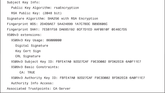
When working with certificates, OpenSSL is an amazingly valuable tool because it enables you to display the certificate content in a human-readable format. Example 4-7 shows a CA certificate with the attributes previously discussed.
Example 4-7 Using OpenSSL to Display Certificate Content


A user certificate will not have the CA:true constraint option. (It will have either CA:false or no such option at all.) Now try to import a user certificate as CA, and look at the CLI output in Example 4-8.
Example 4-8 Importing a Non-CA Certificate During Trustpoint Authentication

Although the messages are confusing, a warning displays to inform the user that the imported certificate is not a CA certificate.
In the example, the trustpoint is configured to use terminal enrollment, where you will be required to paste the CA certificate through the CLI. Because there is a failure message, it is retried in Example 4-9 with debug crypto pki transactions enabled.
Example 4-9 CA Authentication with debug Enabled
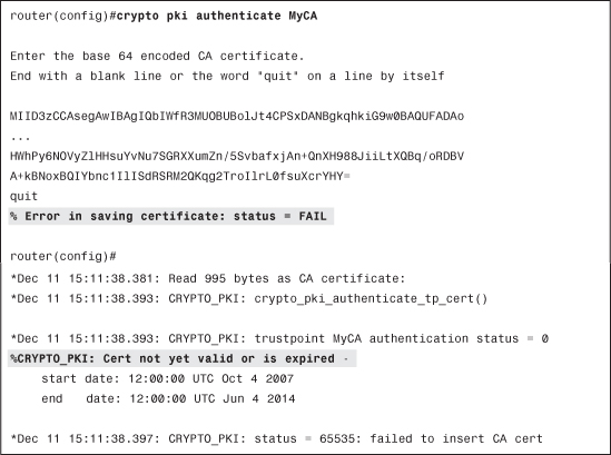
You can immediately see that the problem is related to the clock of the router. NTP is not configured, so the router clock is far behind, and therefore the CA certificate is not considered as valid.
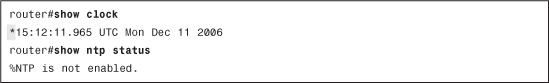
In Example 4-10, the * character in the show clock output indicates an unsynchronized clock. The proper solution is to configure Network Time Protocol (NTP) on the router to have its clock synchronized with an accurate external time source. It can take a few minutes for NTP associations to synchronize and have the router clock adjusted. The show ntp status and show ntp associations commands are useful to verify the actual status.
Example 4-10 Device Clock Is Not Synchronized
Note
If you don’t have an NTP server available within the perimeter of your organization, you can use one of the publicly available time sources. You can find more information at the following URL: http://www.pool.ntp.org/en/.
Using an uncontrolled NTP server can open some security risks. It is therefore advised to use a trusted time source when possible and to enable authentication when available.
Example 4-11 Adding and Verifying NTP Configuration


Note
The time displayed in Example 4-11 uses Coordinated Universal Time (UTC), which can differ from your actual time zone. Certificates use the same reference time. To have the router display the correct time for your location, you might want to configure the timezone using the command clock timezone <timezone-name> <offset-from-UTC>, for example, clock timezone CEST 2 for Central Europe Summer Time. You need to understand that time zone configuration affects only the display and not the actual router clock.
Now you can import the certificate without a problem.
Example 4-12 Successful CA Authentication After Clock Has Been Synchronized

Following are two comments about the process:
• The first attempt does not include the PEM headers, whereas they were pasted in the second try. Both scenarios are accepted: The pem keyword in the configuration is targeted for the CLI output, as you see later in the Certificate Signing Request (CSR). This helps you so that you don’t need to manually add those headers when pasting into your CA GUI, for example.
• During the authentication process, there was a prompt to verify the CA fingerprint to validate that it is correct. There was also a notification that the CA was actually a subordinate CA (that is, not a root CA); therefore, a complete verification chain was not installed.
To validate the entire certification path, you should ideally install all the CA certificates up to the Root CA. However this is not mandatory, and Cisco IOS enables you to install and trust only the bottom part of a certification tree. Obviously, only the certificates issued by a trusted CA (or trusted subordinate CA) will be considered valid; therefore, you should pay attention to that point when working with complex PKIs involving multiple subtrees. Always ensure that the common point is installed as a trusted CA.
After the CA (trustpoint) certificate has been installed, you can proceed with the enrollment phase. This is a two-step process. The first step is to generate a CSR enrollment request. The second step is to have the actual certificate issued by the CA and communicated back, in some way, to the requester.
To create the CSR, the Cisco device uses the trustpoint configuration section to determine which fields must be included in the request. Selectable fields are FQDN, IP address, serial number, and subject distinguished name (DN). Select the appropriate ones based on what information you consider relevant for identification purposes and therefore you would like to see included in the certificate. Depending on the CA, the authority has the capability to modify that information (for example, through templates) by adding or removing some fields. This is entirely dependent on the CA implementation and the way it is configured and operated.
When using enrollment via CLI (terminal), the CSR is displayed on the terminal (as shown in Example 4-13) and must be copied and pasted to the CA.
Example 4-13 CSR Is Displayed on Terminal Console
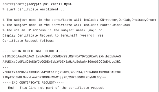
If the trustpoint does not contain configuration settings for all options, you are prompted to include them in the request. The example did not determine whether the IP address should be included. You can clearly see that the PEM headers have been displayed as per the configuration in Example 4-14.
Example 4-14 Trustpoint Configuration References PEM Header Use

Using OpenSSL, you can visualize the content of the CSR, as shown in Example 4-15.
Example 4-15 Using OpenSSL to Visualize CSR Content
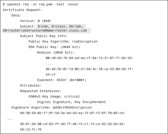
As expected, you have only FQDN and DN in the request. The CSR must then be processed by the CA and, if granted, a certificate will be returned. When the certificate is available, it must be imported into the Cisco IOS device. The complete process must be performed using the same method (either terminal or SCEP), unless you change the trustpoint configuration in between.
Example 4-16 tries to import a certificate (for enrollment) corresponding to the CSR of another router. (Router-A and router-B are mixed up by mistake.)
Example 4-16 Importing a Certificate Not Matching CSR

As displayed, the router cannot find the corresponding key pair, so it rejects the certificate. If SCEP is used as enrollment mechanism, it is more difficult to see the content transmitted at each step because part of it is encrypted.
Note
For complete details about the protocol, SCEP is defined in an IETF draft. The current version is draft-nourse-scep-21.txt and can be found at http://tools.ietf.org/html/draft-nourse-scep-21.
The steps are the same: authentication, enrollment request, and then certificate installation, which are summarized in two Cisco IOS CLI commands shown in Example 4-17.
Example 4-17 CLI Commands Required to Complete Enrollment
![]()
Both commands initiate an HTTP connection to the URL specified in the trustpoint configuration. You should therefore ensure that the connection can be established; routing, firewalls, or access-lists must all be properly configured. A good test is to initiate a telnet from the device toward the CA server, on port 80. Use the correct source interface (as configured under the trustpoint config section) and the destination IP address and port number. If DNS is used, ensure that the name can be resolved correctly (and in the proper VRF) first. The corresponding test CLI would be
telnet <CA-server> 80 /source-interface selected-source-interface.
When launching the authentication command, the URL shown in Example 4-18 will be fetched.
Example 4-18 SCEP URL to Retrieve CA Certificate

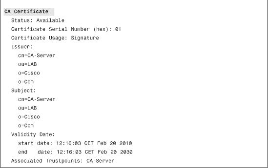
This returns the CA certificate. You can actually try to connect to the same URL using a Web browser, and you can download and view the content of the CA certificate. If you enable PKI debugs (transaction, calls, messages), you can see the exact URL fetched and the response from the SCEP CA server. If this step fails, check connectivity and the clock as previously explained. After authenticated, the CA server appears in the list of installed certificates, which you can display through the command in Example 4-19.
Example 4-19 Displaying Certificates Installed on the Device

You can now proceed to the enrollment phase, as shown in Example 4-20.
Example 4-20 Device Enrollment

The request is now pending on the CA server. Using the preceding command, you can verify the fingerprint of your request so that it can be matched during the verification process with the CA.
When using SCEP, the Cisco IOS device periodically polls the CA server to see whether the request has already been processed and returns granted or rejected. You can view when the next attempt will be triggered, using the show crypto pki timers command, as shown in Example 4-21.
Example 4-21 Displaying Pending PKI Actions (Time-Based)

In Example 4-20, the router retries in 4 minutes and 12 seconds. The time counter should be decreasing as you repeat the command. The request must now be processed on the CA side, as previously described in Chapter 3, “PKI Processes and Procedures.”
At the next poll, two cases are possible:
• If the request has been rejected, the following message will be displayed, as shown in Example 4-22.
Example 4-22 Log Message When Enrollment Request Has Been Rejected by CA

• If the request has been granted, and the certificate signed by the CA, the router notifies through the following log message, as shown in Example 4-23.
Example 4-23 Log Message When Certificate Has Been Granted by CA
![]()
There will now be installed certificates for the CA and the router, as shown in Example 4-24.
Example 4-24 Displaying Installed Certificates: Both CA and Device Certificates

The certificate setup process is now complete and ready to be used.
Certificate Use and Validation
To explain the certificate use and validation process, consider the example of the analysis of the complete debug output during the initiation of an IKE/IPsec tunnel between two Cisco IOS routers.
Following is the scenario:
• Two routers (A and B) enrolled using SCEP to CA-server.
• Router-A is also part of another PKI infrastructure used for other purposes (enrolled to OtherCA-server).
• CRL checking is enabled on all devices, and the CRL file is provided over HTTP by HTTP-server host.
The IP addressing scheme follows:
• Router-A: 10.3.1.11
• Router-B: 10.3.1.12
• CA-server: 10.3.1.1
• OtherCA-server: 10.3.1.2
• HTTP-server: 10.3.1.1 (same as CA-server in the example but could be different)
The lab troubleshooting setup is shown in Figure 4-1. CA and OtherCA are the hostnames of the devices, whereas CA-server and OtherCA-server are the names given to the Certificate Server processes configured on the respective devices.
Figure 4-1 PKI Troubleshooting Lab Setup

To watch the IKE authentication process including PKI, the debug output on Router-A and Router-B has been enabled, as shown in Example 4-25.
Example 4-25 Useful debug Output to Enable

Router-A is initiating the IPsec connection, as shown in Example 4-26.
Example 4-26 Initiation of ISAKMP Connection
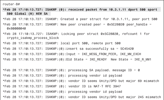

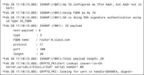
Certificates (RSA signatures) are used for ISAKMP authentication, as shown in Example 4-27.
Example 4-27 RSA Signature (Certificate) Authentication in Use


A certificate request (CERT_REQ) is received from router-A, as shown in Example 4-28.
Example 4-28 Receiving Certificate Request from Peer
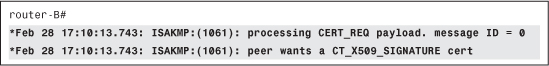
Router-A indicates which CA it trusts: OtherCA-server, as shown in Example 4-29.
Example 4-29 Decoding the CERT_REQ Payload
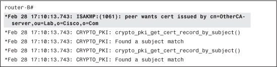
However, router-B is not enrolled with OtherCA-server, so it is impossible to provide a suitable certificate, as shown in Example 4-30.
Example 4-30 Unable to Satisfy the Request
![]()
The request from router-A actually contains multiple CERT_REQ payloads, so router-B processes the next one, as shown in Example 4-31.
Example 4-31 Processing the Next CERT_REQ Payload

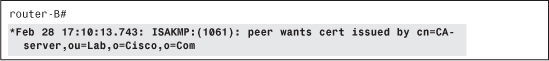
Router-A also indicates that it trusts CA-server, as shown in Example 4-32.
Example 4-32 Decoding the Next CERT_REQ Payload
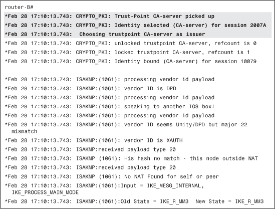
This is a CA that router-B also trusts and is enrolled with. You can therefore choose that trustpoint for your authentication process, as shown in Example 4-33.
Example 4-33 Finding an Appropriate Trustpoint to Answer
It is now your turn to send a certificate request (CERT_REQ) to router-A. You can trust only CA-server, therefore, your request needs to contain only one such payload, as shown in Example 4-34.
Example 4-34 Preparing Our Own Certificate Request

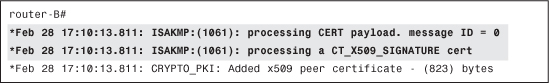
Router-A sent you its certificate (CERT) and an associated signature (to prove that it has the corresponding private key), as shown in Example 4-35.
Example 4-35 Receiving the Certificate from Peer Router
A frequent problem occurs when the sending router displays a message that the certificate is sent but no corresponding entry is seen on the receiving device. IKE packets containing certificates are usually large IP packets (the size increases with the key length), often causing fragmentation to occur. Because some intermediate devices (firewalls, for example) do not handle IP fragments correctly, the certificate packet (or part of it) can be dropped in transit. Testing with varying key sizes usually confirms such problem; although logs on intermediate device, if available, can also show the drops.
If an error occurs during the processing of the certificate payload, the most frequent reasons are as follows:
• Encoding issue caused by the use of special characters, for example
• Structure issue because of the presence of some unusual or nonstandard fields
• Unusual key length or algorithm
For those cases, the most efficient approach is to obtain a copy of the certificate and parse it through the OpenSSL tool to visualize its content in a human readable format and compare it with known-to-work certificates.
Back to the scenario, you have not seen this certificate recently (it is not cached), so you need to perform the complete validation process for it, as shown in Example 4-36.
Example 4-36 Received Certificate Is Unknown (Not Cached)

The validation path has only one certificate (directly the root CA), as shown in Example 4-37.
Example 4-37 Starting the Validation Process
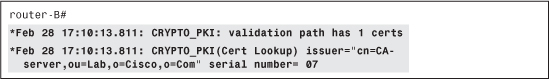
Router-B uses different criteria to find the corresponding CA certificate to use during the verification. In the present case, the issuer name lookup is successful, as shown in Example 4-38.
Example 4-38 Finding the Appropriate CA to Use for Validation


If an error occurred here, it is possible that despite the issuer name match, the actual CA certificate is not the one that issued the certificate. How is that possible? Anybody can create a CA certificate with the name of its choice. However, the key pair used to sign certificates is unique and cannot be re-created. Using an incorrect key pair can cause verification operations to fail.
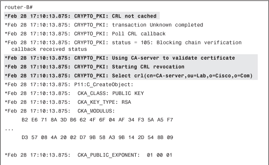
Now verify that the certificate provided by router-A has not been revoked (listed in the CRL), as shown in Example 4-39.
Example 4-39 Starting Certificate Validation Against CRL

In your setup, the CRL location (CRL Distribution Point - CDP) is referenced in the certificate itself through a CDP URL: http://10.3.1.1/cgi-bin/pkiclient.exe?operation=GetCRL. (See Example 4-40.)
Note
For demonstration purposes, the same URL was used as the one automatically used in the SCEP protocol. However, the URL could be anything that points to the correct CRL file on the HTTP server.

Your HTTP GET is successful, and you receive the CRL file in reply. If you suspect a problem at this step, you can always fetch the CRL from a web browser using the displayed URL. The file can be processed by OpenSSL.
The path between your router and the CRL server might be different than the path between your computer and the CRL server: access-lists and firewalls must be opened accordingly. The most common protocols for CRL retrieving are HTTP (either through SCEP or a direct file download) and LDAP.
If a proxy is used to offload the web servers, it is possible that a cached, expired CRL file is returned to the requester (see Example 4-41.)
Example 4-41 Receiving CRL from Server

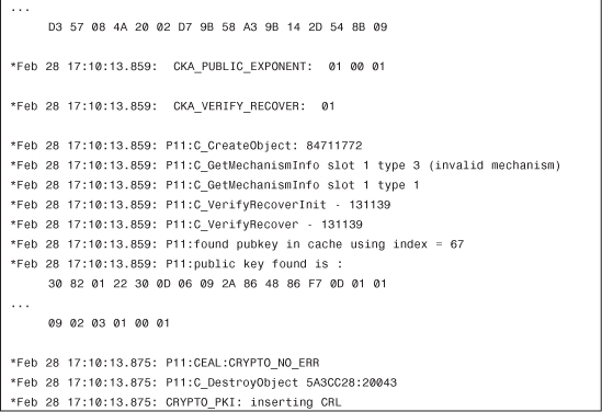
Every CRL has a lifetime, set by the CA when signing it. (see Example 4-42).
Example 4-42 Not Caching CRL (as Per Configuration)

For the test, you have configured router-B not to store (cache) the retrieved CRL files. By default, the router would cache it until the next CRL update time, as shown in Example 4-43.
Example 4-43 Validating Certificate Against CRL

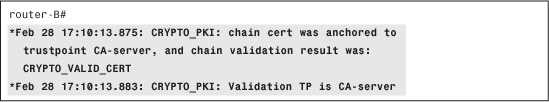
The certificate has been validated, so you can continue the IKE authentication process, as shown in Example 4-44.
Example 4-44 Successful Validation

Verify that the key-usage mentioned in the certificate is adequate for your purpose (here ISAKMP authentication, which requires digital signature). (See Example 4-45.)
Example 4-45 Verifying Certificate Key Usage
![]()
If an error occurs here, it is possible that the certificate contains some unusual or unknown settings for key usage. You get the final status of the certificate validation process, as shown in Example 4-46.
Example 4-46 Final Validation Status (Successful)
Some attributes from the certificate could be used (in a certificate map) as match criteria for mapping to a given ISAKMP profile. This is not used here (see Example 4-47).
Example 4-47 Looking for Matching ISAKMP Profiles (Not Used Here)


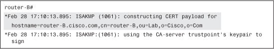
It is now your turn to present your certificate to your peer (router-A) so that through the same process, you can be authenticated, as shown in Example 4-48.
Example 4-48 Presenting Our Certificate to Peer
Note
Looking at the debug output on router-A would show the exact same steps.
For reference only, Example 4-49 shows the remaining ISAKMP and IPSec debug output. As it does not contain any PKI related message, it is not analyzed here.
Example 4-49 Final ISAKMP Negotiations (Not Analyzed Here)
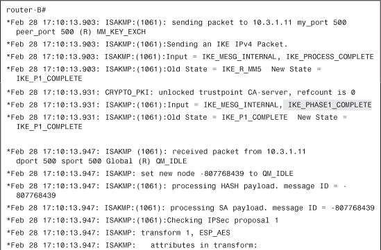


At the end, the complete bidirectional authentication process was successful, leading to an established IPsec tunnel between router-A and router-B, as shown in Example 4-50.
Example 4-50 IPsec Tunnel Established

The example analyzed earlier shows you all the steps performed during the use of certificate-based authentication. This is an IKE/ISAKMP-based example, but any authentication process would be similar.
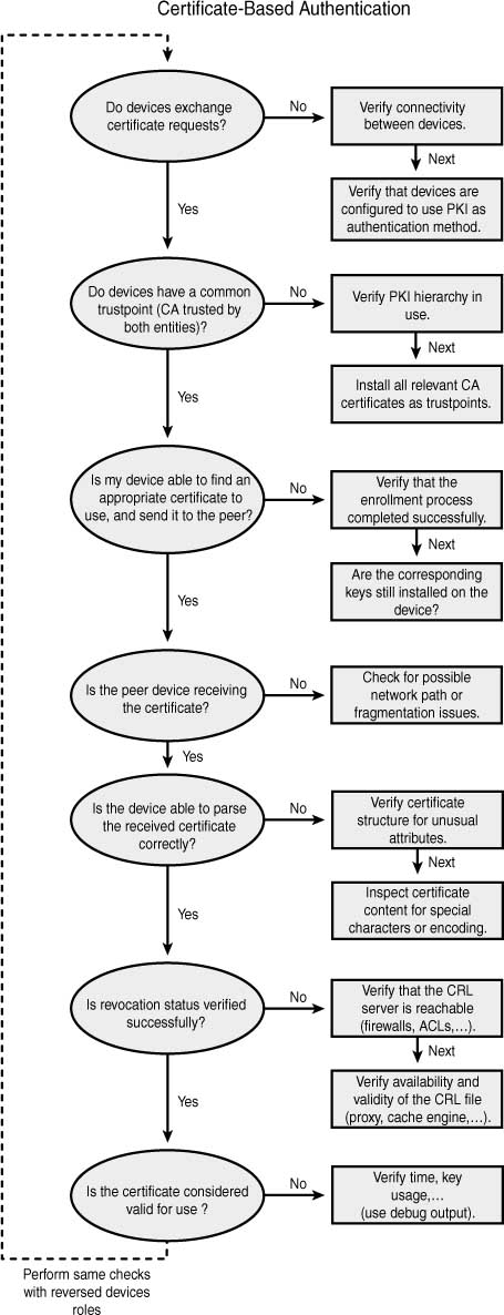
Troubleshooting Flow Charts
The flow charts in Figures 4-2, 4-3, and 4-4 illustrate the troubleshooting processes for initial configuration and key generation, CA authentication and enrollment, and certificate-based authentication.
Figure 4-2 Troubleshooting Initial Config and Key Generation

Figure 4-3 Troubleshooting CA Authentication and Enrollment

Figure 4-4 Troubleshooting Certificate-Based Authentication
Summary
This chapter analyzed some of the common issues that can affect you during the lifetime of your PKI deployment. Because it is impossible to list all possible failure scenarios, details about the expected successful workflow was shown. Based on that information, you can identify deviations that would potentially be the cause of the problems you observe.
For most troubleshooting processes, a good theoretical background can drastically help you understand the debug messages and the expected workflow. This is fully applicable to PKI technologies as well.